More on this below the image...
Click on the image to go back to the Photo Gallery
The photographer's stamp on this photo reads: HALL & CO. Commercial Photographers 20 Hunter Street Sydney
Copyright © 2014 Email - totehis@hotmail.com
More on this below the image...
Click on the image to go back to the Photo Gallery
The photographer's stamp on this photo reads: HALL & CO. Commercial Photographers 20 Hunter Street Sydney
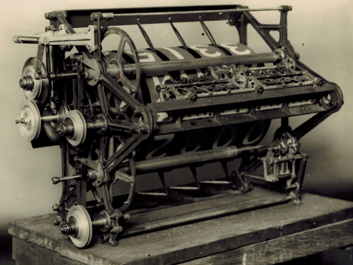
The backs of the 42 adders, that are exactly the same as the one in the image above, can be seen in the image below showing the inside of the Julius Tote second enclosure Machine Room at Bombay. There are 21 of these Combined Adder and Indicator Units in the first row of equipment seen attached to the wall in the image below and another 21 in the second row. There are another 6 of these adders in this machine room, 3 in the top row and another 3 in the bottom, that are out of view off the right hand side of the image below. The front side of these combined adder and displays have their drum indicator window visible on the outside of the building, where together they look like a large indicator board that the public can read. This indicator board, shows the runner totals for 24 Win Pool Units with a Win Pool Grand total Unit, which is replicated for the Place Pool giving a total of 50 of the Combined Adder Indicator Units shown in the image above. It is known that there was at least one other enclosure in this Bombay installation with another 50 of these units.
Machine room view inside Bombay Grandstand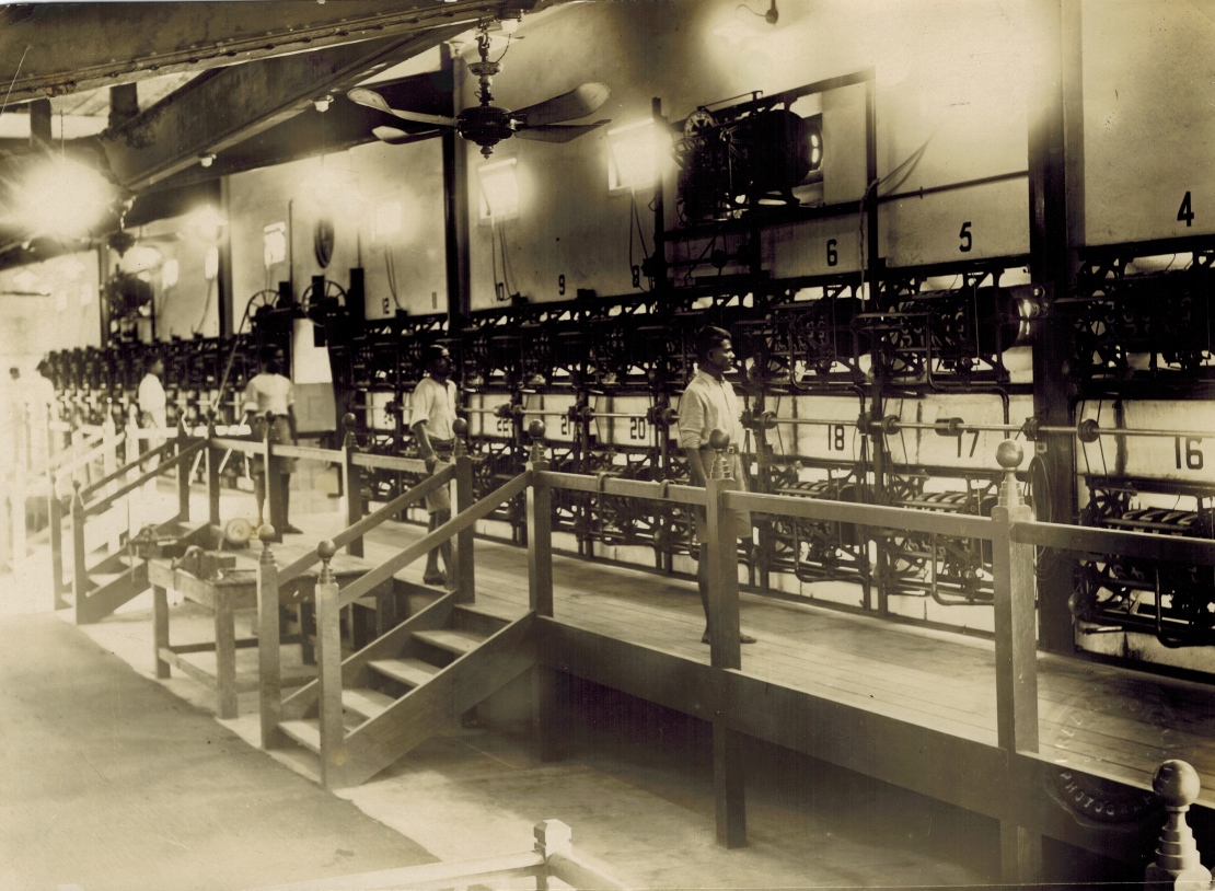
In a company document titled Straight Betting, there is an image of two combined adder and counter wheel indicator units on page 4. One of these two units is of the same type as the one shown in the image at the top of this page. The annotation for this same type of unit in the document reads Horse Unit of medium sized machine. Associated text indicates that the largest type unit has recorded over 250,000 bets per minute, the medium size records at 3000 bets per minute and the small machine at 1000 per minute. Page 4 of Straight Betting is shown in the image at the bottom of this page. It may be surprising to find that in this company document, the Combined Adder and Indicator Unit utilised in Bombay, a system that was the world's largest totalisator, is regarded as a medium sized machine. By the time the company document was produced however, there were larger systems available. In conclusion, the Combined Adder Indicator Units seen in the two images above are each capable of recording 3000 transactions per minute.
The adding shafts with their epicyclic gear arrangement, escapement wheels and solenoids that are activated by Ticket Issuing Machine (TIM) pulses are not clearly visible in the image at the top of this page. The largest by far of the two shaft adder assemblies in this Combined Adder Indicator Unit can be seen mounted on the two interconnected parallel bars running horizontally across the length of the unit about half way up and projecting out of the photo, if it were three dimensional, making them the nearest part of the adder. This shaft adder assembly, consisting of two shaft adder sub assemblies is mounted on the inside of the parallel bars and slant away from the bars at what looks like about 60 degrees from vertical into the photograph, towards the counter wheels stopping short of the upper tubular large shaft that also spans the length of the unit with the large cog attached to the left hand side.
Having mentioned the upper large tubular shaft that spans the length of the unit with the large cog attached to the left hand side, this is a very interesting piece of mechanical technology. This device was called a Storage Screw, however nowadays we would think of it as a type of memory. I suspect this might be the first use of the word Storage, that implies memory as it does in the much later electronics and computer industries. A good digital computer analogy to this storage screw is a buffer memory! There is a second storage screw in this adder/indicator unit seen at the top of this page, near the bottom with almost the same dimensions and orientation, except for the shorter tubular section. The adding shaft assembly that drives the lower Storage Screw is a lot smaller than the upper adding shaft assembly, yet is clearer to see as the assembly is vertical rather than slanted away from the viewer. These Combined Adder Indicator units were custom made for each installation and I suspect that the number of TIMs these Adder/Indicator Units had to support, was only slightly above that which the upper adding shaft assembly could handle.
The need for the storage screws originated from a problem associated with inertia. The adding shafts with their escapement wheels and epicyclic gears could respond quickly to the demands of betting, as they were relatively light with little inertia. These adding shafts in general including the ones identified in the image at the top of this page, record transactions as rotational displacement of the output shaft. In the case of the adding shafts in the Adder/Indicator Unit at the top of this page, the output of the adding shafts is registered in their associated storage screws via a cog on their right hand sides. When it came to driving large counter wheel indicator displays however, like the ones on the front of this Adder/Indicator Units, significant inertia had to be catered for and that is the purpose of the storage screws. In simplistic terms, as transactions are recorded as increments of rotation generated by the fast adding shafts, this rotation winds a screw into the Storage Screw's tubular body as quickly as the adders can register the bets keeping up with the requirements of the bet traffic. At the other end of the Storage Screw, in this case in the image at the top of this page, the left hand end with the large cog mounted on it, the nut is unwound from the screw accelerating as fast as the large counter wheels can. The counter wheels, will eventually reach an angular velocity in excess of the internal screw and start to return the internal screw to its point of origin. The amount the screw is wound in, is the same as the amount it has to be wound out until it returns to its point of origin and that is how the storage screw fulfils its memory function. The Storage Screw mechanism also facilitates the gradual slowing down and eventual gentle stop of the counter wheels as again their inertia prohibits them stopping as quickly as the adding shafts and shock becomes a problem if the reduction in angular velocity is not controlled properly.
The image below shows Figure 11 extracted from George Julius' white paper that he presented to the Institution of Engineers Australia in 1920. Figure 11 has a title EPICYCLIC ADDING MECHANISM with a subtitle SHOWING 'ESCAPEMENT' GEAR. These two titles apply to the equipment drawn in the right hand one third of the drawing. The equipment to the left of this, all shows the Storage Screw with its long horizontal tubular body which George refers to as the nut. The following is my simplistic conceptualisation of the storage screws, as I have never worked on any of the Julius Totes, nor even seen an actual Julius Tote Adder anything like as old as the one at the top of this page, nor seen an actual Storage Screw of any sort. I worked on the computer totalizators the company produced long after Julius tote production had ceased. I initially found the analogy of the nut and screw a little hard to comprehend, however I think this is because of some preconceived ideas which the drawing below helped dispel. One thinks of a nut as relatively short and a screw as relatively long. Additionally one tends to think of one end being stationary with the screw being held in position whilst a nut is tightened on it or the screw rotating into a fixed or held nut. In contrast, the nut in the Storage Screw was long and the internal screw was short and both nut and screw rotate! The nut in the Storage Screw is the long tubular section, as previously identified in the image at the top of this page, which is threaded on the inside. This is shown in the image below where two representative sections of the thread have been drawn at the left and right ends of the central section of the Storage Screw, that has the most internal white space. The short internal screw can be seen inside the far left hand end of the Storage Screw body in the drawing below. The vertical pulley across the left hand end of the Storage Screw straddles the middle of the internal screw. The counterpart to this pulley in the Adder/Indicator unit seen at the top of this page is the large cogwheel at the left hand end of both Storage Screws. To the left of the left hand pulley in the drawing below, the internal screw has the thread drawn on it. At the right hand end of the internal screw in the drawing below, you can see the Internal Screw Driving Rod entering the centre of the screw. I think that as the internal screw is driven further into the body of the Storage Screw, the driving rod will completely pass through the internal screw. The right hand end of this Driving Rod is attached to the output of the Shaft Adder drawn on the right hand side of the Storage Screw. The tubular nut rotates in the opposite direction to the adding shaft driving the internal screw when viewed from their respective ends, if the internal screw is not in its rest position effectively unwinding the internal screw until it returns to its rest position. In the drawing below the internal screw is seen in its rest position at the left hand end of the storage screw body. The internal screw, looking a bit like a grub screw, is short in comparison to the length of the storage screw tubular section, allowing it considerable movement up and down the tubular section. This internal screw is wound into the nut, moving it towards the right, driven by the fast adding shaft via the Internal Screw Driving Rod.
Storage Screw and Adder Engineering Drawing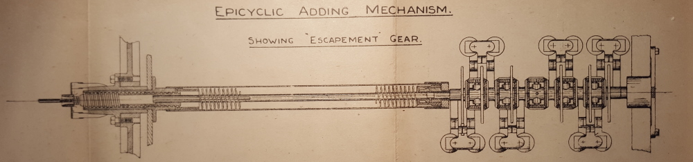
I do not know anyone who worked on the Julius Totes who even remembers the storage screws. To my knowledge, the need for them was eliminated when George Julius invented the odds calculators in 1927 and in particular the barometer indicators became very popular. This meant there was no more need for the large drum counter wheels with their inertia limitations, to show the investment on each runner. That is why none of the people who worked on the Julius Totes in the latter period of their production remembers storage screws. Having mentioned inertia limited drum counter wheels, there were systems with much larger counters than those seen on the adder/indicator at the top of this page. Neville Mitchell mentions them when he saw one in operation in Bangkok in 1969. Following is a comment extracted from an email he sent me about them in 2010: When the betting was as full speed as it was most of the time, the erratic stop start action of the drums caused the building to "shake". In the absence of any firsthand knowledge relating to the storage screws, my current conceptualisation is that the internal screw has probably got an internal parallel keyway. The Internal Screw Driving Rod from the adders is keyed and passes through the centre of the threaded tubular part of the storage screw as well as the internal screw itself. The key passes through the internal screw keyway allowing the driving rod to turn the screw whilst allowing the screw to travel along the threaded shaft, driven either by the rod turning the screw, or by the rotation of the surrounding nut or both. The pulley mounted on the left hand side of the Storage Screw in the drawing above and the large cogs on the left hand end of the two Storage Screws in the image at the top of this page, also drive the large drum counter wheels on the Adder/Indicator Units.
I have chosen the image at the top of this page to write about the mechanism that locks the driving gear as this image has the most prominent view of this part of the machinery. Following is a short extract from a Paper George Julius presented to the Institution of Engineers Australia in 1920. This extract relates to the storage screw:
The epicyclic gears are made as light as possible, and are urged forward by " coil springs " and not by "weights." This ensured the instantaneous response of the epicyclic gears to the demands of the ticket-sellers. The movement of these gears so obtained is transferred to a " storage " screw which serves two functions, firstly, that when the machine is at rest it locks the driving gear which operates the counter wheels, and, secondly that when issues are to be recorded, it stores-up the records until they are registered by the counters. Immediately the tickets are issued the epicyclic gears instantly operate, being driven by the coil spring, and in so doing they turn the screw which then unlocks the driving gear for the counter, and the counter begins to operate. In so operating, this driving gear also moves a nut, which, acting on the storage screw, tends to bring it back to its normal position of rest, and thus again lock the counter driving mechanism. Thus the epicyclic gears in picking up impulses received from the ticket-sellers move the screw backwards, and the, driving gear of the counter is always trying to overtake this movement and thus return the screw to its normal position.This locking mechanism George mentions, can easily be seen in the image at the top of this page. On the left hand side of the adder inside the left hand side of the mounting frame there are two large cogs with tubular storage screws at their centre. These cogs are the means of rotating the nut or tubular body of the storage screws. This description applies to both of them but I will describe the locking mechanism associated with the top large cog. From the centre of this upper large cog, come left past the left hand side mounting frame of the adder/indicator and you see a rod projecting left from the circular centre of the Storage Screw body. This is part of the storage screw position sensing mechanism. At the point where this rod, which I will call the Storage Screw Position Sensing Rod, disappears into the Storage Screw tubular section, there is a bracket attached to the left hand mounting frame of the adder, through which the Storage Screw Position Sensing Rod passes. This bracket has two arms extending upwards and left at 45 degrees to the horizontal Storage Screw with a rod across the tips of the arms acting as a hinge. Attached to this hinge is a moving arm consisting of two metal strips forming a lever projecting downwards to the drive pulley for the small cog that drives the large cog wheel that we started with in the first place. At the bottom end of this downward lever, which I will call the Stop Deployment Lever, there is a projection toward the pulley, that engages with one of two stops on the back of this Storage Screw Nut driving pulley. This is the means by which George's at rest it locks the driving gear which operates the counter wheels is achieved. The pulley driving the cog that drives the large cogwheel can clearly be seen in another drawing in George Julius' white paper titled Figure 10 that can be seen in the Machanical Aids to Calculation chapter of this website. This projection on the bottom of the Stop Deployment Lever and the associated two stops on the pulley are hidden behind this Storage Screw Nut driving pulley, in the image at the top of this page. The two stops on the back of the Storage Screw Nut driving pulley can be seen in another image of the adder/indicator unit shown at the top of this page, which I have not included on this website. The two stops are implemented as two projections on the extremities of a strap that is mounted on the back of the pulley across its axle. This type of stop can be seen however at the the right hand extremity of the drawing above, mounted on the right hand side of the wheel at the at the right hand end of the adding shaft. The two projections at the extremities of the strap across the axle are the rightmost part of the drawing above bar the centreline marking for the Adding Shaft. This means that the wheel can only rotate a maximum of half a revolution once the locking arm has been deployed.
This lock does not stop the motion of the storage screw driving pulley and its associated belt when it is installed and operating. Again I am describing the equipment associated with the upper storage screw but it applies to both. The pulley has an inbuilt clutch assembly and the spring seen at the left hand end of the shaft the pulley is mounted on seen in the image at the top of this page is a clutch spring. The lock causes the clutch to slip stopping the output shaft of the clutch from rotating and stopping the motion of the large cog we started with. Once the Internal Screw starts to move, driven by the he Internal Screw Driving Rod as a result of transactions being recorded from the adding shafts, the first thing that happens is the Storage Screw Position Sensing Rod starts to move into the body of the Storage Screw. This allows the locking leaver arm to disengage the lock and allow the drive pulley to rotate the large cog through the clutch. This turns the nut part of the storage screw and begins the process of winding up the Drum Counter wheels to catch up with the bet traffic eventually returning the Internal Screw back to its rest position where the lock is engaged again, when there is a lull in the bet traffic. As mentioned, the drive to the pulley being discussed is continuous yet betting is start stop and during a betting spell the rate varies so in general terms, this accommodates the nature of betting which is erratic. There has to be a means of disengaging from the constant drive to the calculating equipment when no betting is taking place and that is the reason for the clutch. There are some video clips in the Video clips of a working Julius tote chapter of this website that show this release mechanism associated with the Storage Screws working. The adders in the video clips are more modern than the one in this image and are larger, being mounted on tables. The audio track on these video clips clearly conveys the clanking sound of these locks being disengaged and reapplied. The clips that show these locks in operation are titled The forecast pool adders and Place GT and forecast adder internals. These can be viewed here. In these clips these locks are continuously released and almost immediately reapplied. This is due to light bet traffic. During heavy betting the Storage Screws would spend most of their time outside the rest position with the Drum Counters keeping up with the Shaft Adders after having reached flank speed.
What the wheel on the adding shaft at the far right of the drawing above is I am not sure. As it has part of a stopping mechanism on its right hand side it could be a pulley and a clutch, the clutch being required when the stop is engaged to separate the constant drive of the belt from the erratic motion of the adding shaft. In the drawing above, if this right hand wheel is a pulley and clutch then it could be used to wind the adding shaft spring up, which is not shown in the drawing. On the other hand, in the second extract from George's white paper which appears below, he states The rotation of the nut also is utilised to continually rewind the coil spring which operates the epicyclic gears, the epicyclic gears being part of the shaft adder. In other words, apart from turning the nut or body of the storage screw, the wheel at the left hand end of the drawing above is also winding the adding shaft spring up, which means the wheel on the right hand end of the drawing above would not be used for winding the adding shaft spring. It is probable that the storage screw seen in the drawing above has a somewhat different implementation to that of the adder/indicator unit shown at the top of this page. It is already different in that the drawing above shows the adding shaft in line with the storage screw with the left hand end of the adding shaft driving the right hand end of the storage screw, whilst in the adder/indicator unit at the top of this page the adder assemblies drive the storage screw via a pair of cogs at their right hand ends. The Storage Screw Position Sensing Rod can be seen in the drawing above extending out of the left hand end of the Storage Screw.
On the subject of not being sure, I am not sure why there is what looks like a pulley on the left hand end of the storage screw body in the drawing above. All the storage screw photographs I have seen have a cog driving the nut or tubular part of the storage screw like the ones in the adder/indicator unit in the image at the top of this page. If this left hand wheel on the left hand side of the drawing above is a pulley, then it may have an inbuilt clutch like the storage screw driving pulleys on the adder/indicator unit at the top of this page. The darker middle section of the pulley may be indicative of a clutch plate! If this is a combined pulley and clutch on the left hand side of the drawing above then the wheel at the far right hand side might purely be a stop wheel and when it is stopped it may cause the clutch in the pulley on the left hand side to slip. In this way the constant drive belt continues to turn the pulley but the pulley no longer drives the nut as the clutch is slipping. As the control section of the storage screw is not shown in the drawing above, it is not possible to determine if any of this speculation is correct.
A second extract from George's paper mentioned above reads:
The movement of this screw is so arranged that it also controls a variable speed friction gear through which the counters are driven. During any period of acceleration in the issue of tickets, the screw is withdrawn in the nut faster than the counter operates, and this through the friction gear speeds up the counter, and the nut, in an endeavour to overtake the movement of the screw, and a condition of balance is ultimately established. If the issue of tickets is retarded or ceases, the nut immediately gains on the screw and brings it forward, thereby picking up all the stored-up records, and by means of the friction gear gradually slowing down the counter until when all the records are recorded, it quietly comes to rest. The rotation of the nut also is utilised to continually rewind the coil spring which operates the epicyclic gears, and thus ensure a steady driving effort on these gears.At the left hand tip of the Storage Screw Position Sensing Rod in the image at the top of this page, the rod engages a near vertical lever via a small hinge. The lever looks like a hinged arm projecting down from the left hand end of a long horizontal mounting bracket above, that is attached at its right hand end to the left hand mounting frame of the adder/indicator. This is part of the control system for the variable speed friction gear that George has described. I have never seen one of these adder/indicators, however from the photograph shown at at the top of this page and the following photograph in the Photo Gallery it is possible to determine an overview of how it worked. To find out more, go to the next photograph in the Photo Gallery which shows this adder from a different angle. Click on the image at the top of this page, then click on the following image thumbnail in the index, to that for the image shown at the top of this page.
Looking at the tubular body of the storage screws visible in the image at the top of this page, it can lead to a question. If the internal screw can travel down the length of the tubular section of the storage screw, why is the Storage Screw Position Sensing Rod so short? The reason for this is that the Storage Screw Position Sensing Rod is only required to control the acceleration and deceleration of the inertia limited drum counter wheels. This only becomes an issue when the Storage Screw's internal screw is in the vicinity of its rest position and it is in this vicinity that the Storage Screw Position Sensing Rod becomes operational. In this vicinity the velocity of the Internal Screw either needs to start declining eventually resulting in a gentle stop, when moving towards the rest position, or accelerating to catch up with the adding shaft, when moving away from its rest position. When the Internal Screw is outside the proximity to the rest position, the inertia limited parts of the system, which in this case are the Drum Counters on the Adder/Indicator units, which are driven by the output of the Storage Screw, can continue to operate at flank speed. In other words, it is only when the Storage Screw is nearing empty, that a controlled stop needs to be catered for. I am fascinated by the many analogies to this old computing machinery that exist in today's digital computers and electronics. The function the Storage Screw control system performs during acceleration and deceleration is analogous to an electronics control system called a closed loop servo system.
Firstly, as George Julius has mentioned the Epicyclic Gears in both of his white paper extracts above, which are part of the Shaft Adders in the Adder/Indicator unit shown at the top of this page and secondly, as part of the drawing above shows a plan view of an Adder and finally, because this plan view of the Adder matches both of the Adder sub assemblies constituting the largest adder assembly seen in the Adder/Display unit in the image at the top of this page, I will give a quick description of it here. I have already identified the location of this largest adding shaft assembly in the image at the top of this page. I mentioned that the adding shaft assemblies are not clearly visible in the image and additionally that the largest adding shaft assembly is slanting back at about 60 degrees. This results in these adding shaft assemblies seen in the image at the top of this page providing insufficient detail to make them worth referring to. Therefore I will limit this description to the drawing above titled Storage Screw and Adder Engineering Drawing. This drawing is a plan view and for the not so technical reader, it is looking down from above the equipment just seeing the top of it. The Adder assembly in the drawing consists of all the hardware on the right hand side of the Storage Screw, constituting approximately the right hand one third of the drawing. This shaft adder assembly in the drawing, corresponds to each of the two shaft adder sub assemblies seen in the image at the top of this page that are slanting back at about 60 degrees and are mounted side by side with an epicyclic gear mounted between them to sum the output of each of the two adding shaft sub assemblies.
The adding shaft in the drawing above consists of the shaft segments that look like a continuous horizontal shaft passing through the Adder, that attaches on its left hand side to the Internal Screw Driving Rod seen running along the inside the body of the Storage Screw. Six solenoids with dual electromagnet coils are visible, three at the top and another three at the bottom extremities of the Adder in the drawing. There are six escapement wheels visible which are the six tall narrow oblong rectangles perpendicular to the adding shaft that are aligned with the gap between their respective solenoid coil pairs. Above each electromagnet coil pair where the coils are closest to each other, the armature of the solenoid can be seen. These are the stubby T shaped objects with two + marks at their horizontal extremities seen sitting on top of each coil pair. The vertical part of the T for the top three solenoids and inverted T for the bottom three solenoids can be seen in the drawing above extending towards their associated escapement wheel. These metal T shaped solenoid armatures are magnetically pulled downwards when activated by current flowing through their respective electromagnet coils. This movement of each solenoid armature activates its associated escapement mechanism that allows its escapement wheel to rotate one tooth at a time when recording bets. A drawing of an escapement wheel, solenoid and escapement mechanism can be seen in the second page of the Photo Gallery of this website. To see this drawing, click on the image at the top of this page and scroll down to the bottom of the loaded page and select the Next page button in the navigation bar at the bottom. Then scroll down in the Photo Album index to the heading Figures from George Julius' White Paper 1920 and a Julius Tote Engineering Drawing then select the image thumbnail with the associated descriptive text starting with FIG 12 from George Julius' paper. Five epicyclic gear arrangements are also visible on the adding shaft in the drawing above, each consisting of two horizontally oriented and two vertically oriented bevel gears, required to sum the rotation of the six escapement wheels. These five epicyclic gear arrangements look like vertically elongated boxes straddling the adding shaft. This summing process begins at the far left and far right escapement wheels on the adding shaft and the epicyclic gears cumulatively sum the rotation of these outside escapement wheels with those along the way to the centre. As can be seen in the drawing above, the centre epicyclic gear has no associated escapement wheel. It sums the left hand segment total rotation with the right hand segment total rotation. It receives the sum of the rotation of the left hand escapement wheels on its left bevel gear and the sum of the rotation of the right hand escapement wheels on its right bevel gear. The sum of the left and right hand bevel gears is represented by the rotation of the axle of the upper and lower bevel gears of the centre epicyclic gear around the adding shaft. The small dot like circle in the centre of the centre bevel gear shown in the drawing above, indicates that this rotation of the vertically oriented axle of the epicyclic gear around the adding shaft is connected to the internal output shaft that extends out of the left hand end of the adding shaft and is connected to the Internal Screw Driving Rod inside the tubular section of the Storage Screw body. The vertical mechanism, perpendicular to and near the left hand end of the storage screw is the drive pulley which provides the motive force for the storage screw and the adding shaft.
As previously mentioned, the thin rod extending from the left hand end of the storage screw tubular body in the drawing above, is the Storage Screw Position Sensing Rod. When the Internal Screw after a betting period is in the vicinity of its rest position this sensing rod extends further out of the tube than it is in the flank speed condition and starts the slowing process of the inertia limited part of the system, namely the drum counter wheels. The sensing rod continues to extend, as the internal screw gets closer to its rest position controlling the slow down until the storage screw reaches the rest position and the storage screw is locked, keeping it from moving when the screw is in its rest position. Despite the storage screw being locked, the adding shafts can still operate as they are driven by coil springs. Consequently when betting resumes after the storage screw has returned to its rest position, the Adder starts to wind the internal screw into the tubular body of the Storage Screw, which means the Storage Screw Position Sensing Rod starts to withdraw into the tube causing the lock to be removed starting up the drive for the Storage Screw again as well as wind up the spring driving the adding shaft.
Page 4 Straight Betting
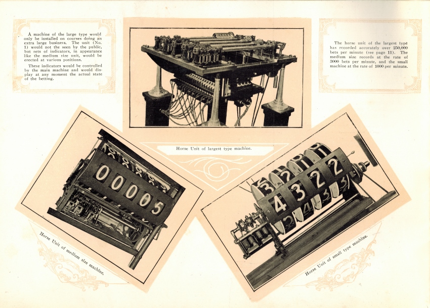
The Horse Unit of medium sized machine mentioned near the top of this page is shown in the bottom left picture in the image above. This picture shows the front view of the adder/indicator unit shown from the rear in the image at the top of this page. Straight Betting refers to this as a Horse Unit as this adder/indicator unit totals the investments on a particular horse as opposed to the pool grand total.
The note inside the top left text box in the image above, to the left of the largest type machine picture reads:
A machine of the large type would only be installed on courses doing an extra large business. The unit (No. 1) would not be seen by the public, but sets of indicators, in appearance like the medium size unit, would be erected at various positions.The note in the top right text box in the image above, on the right hand side of the largest type machine reads:These indicators would be controlled by the main machine and would display at any moment the actual state of the betting.
The horse unit of the largest type has recorded accurately over 250,000 bets per minute (see page 11). The medium size records at the rate of 3000 bets per minute, and the small machine at the rate of 1000 per minute.You can view an image of the largest type machine on this website, which is identical to the one shown in page 4 of Straight Betting above. To view this, click on the image at the top of this page and scroll up to the Photo Gallery section titled Randwick Racecourse Sydney New South Wales, then scroll down again and select the image thumbnail with associated text starting This image shows an ornate early large system adder.