Click on the image to go back to the Photo Gallery
This technology history page contains a photograph which is one of several belonging to the photo gallery pages which are part of several pages relating to the invention of the world's first automatic totalizator in 1913 and Automatic Totalisators Limited, the company founded to develop manufacture and export these systems. George Julius was the inventor of the world's first automatic totalisator and the founder of Automatic Totalisators Limited and was instrumental in the design of all of this electromechanical equipment.
Click on the image to go back to the Photo Gallery
There is no photographer's stamp on this photograph
There is one adder per runner in a race the same as the one in this image, as well as a grand total adder. This is repeated for each pool that the system supported, in this case GAGNANT and PLACE translated from French, Win and Place. Some of these adders are visible in the Longchamps machine room image below. A full sized version of that image can be seen in the first photograph in the Longchamps section of the photo gallery.
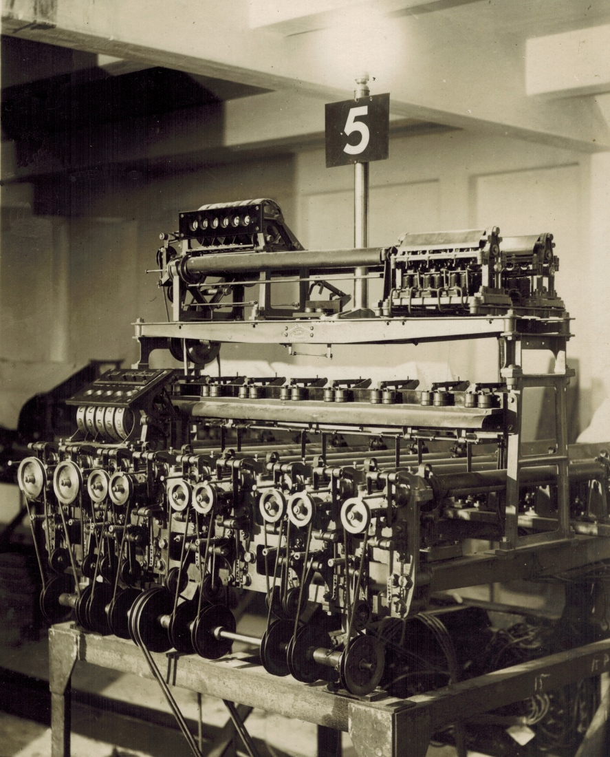
One immediate impression from this adder is that it is functionally implemented as two adders. The first is the equipment on the top of the bridge like section of the adder that supports the post with the number five on it. This equipment drives the counter wheel display seen mounted above the rest of the equipment on this level at the left hand end of the shelf. The second functional adder is most of the remaining equipment below this level which drives the lower counter wheel display panel seen at the left hand end of the lower shelf of the bridge like section of the adder. Above the counter display holes in this second panel there are what appear to be adjustment knobs or buttons. I cannot determine from the highest resolution images I have, what the markings on this panel above these knobs or buttons are, however it is not writing but I can make out that there are two oblong boxes, one above the left knob or button and one spanning the width of the remaining three and they seem to have some markings or symbols inside these boxes.
I presume that the dividend calculation staff working on this Julius Tote would have recorded the contents of these two counters on the adder corresponding to the winner for the Win pool or the adders corresponding to the placegetters for the Place pool and added them together to determine the total investment on the associated runner. Similarly the pool Grand Total adder would be read which would allow the calculation of the dividend. I note that the upper counter display has six digits whilst the lower one has only five. My guess is that the Ticket Issuing Machines attached to the upper functional adder are dedicated to higher values to the ones attached to the lower functional adder.
There are seven tubular sections visible across the mid section of the adder, spanning from near the front of the adder to the rear, below the bridge like upper sections. The right hand support pillar of the bridge section, passes the mid section of the nearest tubular section and is perpendicular to it. At this point I need to explain that although this whole device is called an adder it has eleven constituent shaft adders, one for each tubular section of the adder. At the rear end of these tubes are the solenoids, escapement wheels and epicyclic gear trains belonging to the shaft adders. The rear of a couple of the adders are visible in the first image in the Longchamps photo gallery section showing the machine room. A reduced version of this image appears below however the full sized image provides more detail. The two men on the left of the image below are looking at the shaft adders in the second complete adder on the left.
The tubes mentioned above are called Storage Screws. These remember the value of summed transactions and as such are a mechanical form of memory. The summed transactions are recorded as angular displacement resulting from rotation of the fast adding shafts at the rear of the adder. I speculate that the name Storage Screw may be the first use of the word storage to imply artificial memory. This angular displacement is read at the front of the adder for the slower to respond, inertia imposed acceleration limited parts of the system associated with displaying the total runner investments and pool grand totals for the punters. The storage screws operate on a very simple principle that the angular displacement to which a screw is driven into a nut, is equivalent to the angular displacement of the nut required to remove it from the screw, or to return the nut to its starting position if the nut was already mounted on the screw, as is the case for the Storage Screw. Unfortunately, the mechanical implementation of this principle as a memory is not so simple. The electronic counterpart performing the function of interfacing two devices with disparate transfer rates, as these storage screws mechanically do, became widely known as a buffer memory. An image of a partially assembled Longchamps adder, viewed from the rear, showing the adding shafts and storage screws is at the end of the Longchamps section of the Photo Gallery. To see this image, click on the image above and scroll down and select the last image thumbnail in the Longchamps Paris 1928 section.
Following is a description of one of the eleven storage screws, nine of which are running from the front to the back of the adder. Only seven are visible from this perspective however another two are hidden by the lower counter wheel display panel on the left hand side of the adder. There are another two storage screws on the upper level of the adder running from left to right, the near one being in plain view, with the adding shaft sections visible on the right hand side. In the front adding shaft section of these two, the front row of escapement wheel solenoids are clearly visible and above these, part of the escapement levers can be seen. The epicyclic gear train and the major part of the escapement wheels are hidden by the dust covers sitting on top of the adding shafts.
Back to the front back oriented storage screws. The adding shaft at the back of each storage screw, winds a screw similar to a grub screw up the threaded inside of the storage screw shaft. The slow to respond near side machinery, detects the movement of the storage screw and starts rotating the storage screw shaft in the opposite direction, an action that works to return the storage screw to its rest position. The angular velocity of the storage screw shaft, is controlled by what George Julius describes as Variable Speed Friction Gear. This Variable Speed Friction Gear allows the storage screw shaft, which has been likened to a nut, to accelerate at a rate that inertia allows and eventually achieves an angular velocity greater than that of the storage screw. This occurs either through its maximum velocity being reached or a decline in the betting rate or both, resulting in the storage screw travelling back towards its rest position. The storage screw position sensing equipment, detects when the screw is nearing its rest position and provides feedback to the Variable Speed Friction Gear, to slow the nut down gradually resulting in a gentle stop. This eliminates impact stress to the inertia limited machinery. On the interesting subject of analogies with electronic systems, this sensing, feedback and velocity control system sounds like a closed loop servo system to me.
For the purpose of describing what seems apparent regarding the storage screw position sensing equipment, I will focus on the storage screw on the right hand side of the adder, although this generally relates to all the storage screws, where there are two storage screws paired together, some of the arrangement is the opposite way around. George Julius described the storage screw in a paper he wrote for a demonstration of a system capable of supporting up to 1000 terminals and a sell rate of 250,000 sales per minute, to the Institution of Engineers Australia in 1920. Incidentally George was a major founder of the Institution of Engineers Australia. In that paper he describes the storage screw, which improved my understanding of this memory device, to the extent of being able to write the previous paragraph. I have likened the control of the storage screw to a closed loop servo system. In this analogy, George's description only alludes to the part of this system which would be called the feedback path. The only reference he makes to it is to identify the part which the feedback loop acts on, by naming it Variable Speed Friction Gear. This is the means of controlling the velocity of what George terms the nut, which is the outer tubular body of the storage screw. How the Variable Speed Friction Gear operates, or how the position of the storage screw travelling along the threaded inside of the nut is sensed, is not described. Regarding this part of the system I ascertain what I can from photographs and then resort to speculation about what is probable. George's paper presented to the Institution of Engineers Australia, can be read in the Mechanical Aids to Calculation chapter of this website. To read this, click on the image above, scroll to the bottom of the new page and select the Go to the index option in the Navigation Bar and then select the mentioned chapter in the Firstly section of the index.
Part of the storage screw position sensing equipment, which detects the screw position when it is nearing the rest position, consists of the rods extending from the centre of the ends of the storage screw shafts which act upon an associated lever extending vertically downwards from the right hand side of a pivot point above and slightly behind each of the associated storage screw pulleys. The storage screw pulleys can be seen as nine shiny pulleys, with their circular centres facing the front of the adder, in a horizontal row at a level below the lower counter wheels and display panel on the left. The left two storage pulleys are larger than the rest of the pulleys. The rod in our example we are focusing on, which is the right hand storage screw running from the near side front of the adder to the rear distant side of the adder, is seen protruding out from the centre of the storage screw to a position slightly above and to the right of centre of its associated storage screw pulley.
The storage screw position sensing equipment pivot points at the ends of each pair of arched arms extending up and forwards above each of the screw position sensing rods, seem to have two levers attached to them that work together. There are nine of these pairs of arched pivot support arms clearly visible horizontally across the width of the adder, seen respectively above each of the nine storage screw pulleys. In our example, the right hand lever attached to the pivot point above the storage screw position sensing rod, is the longer and its middle is connected to the storage screw rod which moves the lever. The bottom of this lever pushes on an adjustment screw contained in another lever pivoted below and rearward of the associated storage screw drive pulley. The upper lever pushes the lower lever and a projection on the lower lever seems to engage a projection on the rear side of the storage screw drive pulley which seems to have the effect of locking it from rotating when the storage screw has reached its rest position.
The left hand lever, which looks like it is a bit less than half the length of its associated right hand lever, descends from the left hand side of the pivot point above its associated position sensing rod. The bottom of the left hand lever is attached to another rod that disappears rearward down the left side of its associated storage screw, running parallel to the position sensing rod before it disappears behind the cylindrical body of its associated storage screw. Extrapolating its direction it looks like it connects to a lever that rises to a pivot rod running the width of the adder just below the lower shelf in the bridge like section, that also runs the width of the adder with the left hand end of it hidden behind the lower counter wheel display panel. This rising lever arm then changes direction 90 degrees at the fulcrum, then travels horizontally rearwards and disappears from view behind a cable loom running up the nearest right hand pillar of the adder. This puts it in a position to connect with the activating arm of the right hand Mercury Pot Switch on this lower shelf. There is proof that the rear end of this horizontal part of this right angled lever arm is connected to a rising rod that connects to the rearward end of the activating arm of the associated mercury pot switch. As previously mentioned, there is an image of a partially assembled Longchamps adder viewed from the rear, at the end of the Longchamps Paris 1928 section of the photo gallery, in which the rising rods mentioned can be seen connecting the rear end of the right angled lever to the rear end of the mercury pot switch activating arms. You can see that these rising rods respectively connect to these mercury pot switch arms at a point close to the pivot point but displaced somewhat towards the fork end for a bit of leverage. Due to the proximity of the fulcrum to the rising rod's connection with the activating arm and the much greater distance from the end of the mercury pot arm, a little vertical movement of the rod will produce a proportionately larger vertical movement of the fork end of the arm. The pin like projections above the activating arms of the mercury switches near the hinge with the 45 degree mounting bracket in the image above, are the tops of the rising rods, which reveals the connection point of the rods to their respective mercury switch activating arms. There are seven of these Mercury Pot Switches completely visible on this shelf with another partially obscured and a ninth one completely hidden behind the lower counter display panel at the left hand end. These switches are described later.
After the revelations in the previous paragraph establishing a mechanical connection between the storage screw position sensing mechanism and the associated mercury pot switch, it is with a reasonable level of certainty that I conclude the mercury switches perform some electrical function when the respective storage screw has returned to its rest position or is in the proximity of its rest position. As previously mentioned, the angular velocity of the storage screw shaft is controlled by what George Julius describes as Variable Speed Friction Gear. The method of implementing this Variable Speed Friction Gear seems to differ when looking at different types of Julius Tote Adders particularly when looking at systems built for significantly different sized expected maximum turnovers. The Longchamps system to which the adder shown above belongs, was the biggest totalisator system in the world when it commenced operation in 1928. In this adder it seems the variable friction could be achieved by altering the tension on the drive belts. This is the second speculation in this paragraph. It is hard and sometimes impossible to be sure when photographs are the only thing left to go by. If only I could have a look at any actual storage screw, let alone a complete adder from the Longchamps system or even any adder which implemented storage screws for that matter. If you are reading this expecting a definitive explanation of how this adder works you may find it more illuminating to read about the Western India Turf Club Julius Tote Combined Shaft Adder and Indicator unit, as I have identified the Variable Speed Friction Gear implementation in that adder by much contemplating of photographs and consequently it is less speculative. To read this click on the image above, scroll up in the index to the heading Western India Turf Club Bombay 1925 and click on the last image thumbnail in that section with the associated text beginning with the sentence The front view of the unit in the previous image.
Of the people I know who worked on the Julius Totes, none dated back to the era when Julius Tote Adders utilised storage screws. After George Julius invented odds calculators and Automatic Totalisators Ltd built and implemented them, the need for the storage screws was eliminated as the slow to accelerate large counter wheel public displays of runner totals and pool grand totals were no longer needed. This situation of not having anyone left to talk to who knows something about a piece of long antiquated technology, like the 92 year old at the time of writing adder above, reminds me of a comment that eloquently describes it. It was made by Dr Doron Swade MBE who replied to an email of mine informing him of a new page in this website. Doron is an eminent expert on the history of computers and computing. Following is the pertinent extract from that email: It is splendid that such technical material has been captured while there are folk around to marshal the technicalities and document them. Part of the argument in the book chapter is the need to take advantage of relatively short historical windows to capture operational and technical detail without which objects lapse into obscurity and mystery. After reading this extract, Bob Moran sent an email about it. Bob is a mechanical engineer who has done much restoration work on Julius Totes for exhibition purposes, long after they ceased operation. Bob has also created what he calls the Discovery Shed to inspire young minds and generate interest in Science Mathematics and Engineering. An extract from Bob's Email reads: Thank you for your thoughts, they really resonate with me! You and Doron are spot on, I am always saying there will be no one around to remember how or why things work unless we capture the details now! Bob also made a comment about Sir George Julius: Anyway at least you have done a magnificent job documenting Tote History, especially Sir George Julius' role, which to me is iconic and unbelievable. When I visited the French company PMC (Périphériques et Matériels de Contrôle) in 2008 I discovered the French Engineers, who replaced the Longchamps Julius Totalisator system after it had been in operation for 45 years, with a computer based totalisator system, were so impressed with this Julius Totalisator that they could not bring themselves to discard it all. Instead they took the trouble of arranging a donation to a Paris Museum and donating parts of the Longchamps Julius Tote system to it. Unfortunately I have been unable to trace any part of this donation, as even here the company memories of this event are growing dim and there is uncertainty about which museum it was, so we are left with much speculation regarding the workings of the adder in the image above.
Back to the speculation about altering the tension on the drive belts, there are tensioner pulleys controlling the tension of the main drive belts. These belts run from the drive pulleys on the main drive shaft, which can be seen across the bottom front of the adder, to the Storage Screw Nut Drive Pulleys oriented at 90 degrees to and located in a row above the Main drive Pulleys. The nine tensioner pulleys can be seen in a row between the Main Drive Pulleys and the Storage Screw Nut Drive Pulleys, near the Main Drive Pulleys. The main drive pulleys are driven by the large double pulley near the middle of the Main Drive Shaft. I presume this is a double pulley to implement redundancy to eliminate the possibility of a single main pulley belt failure causing a complete adder failure. The twin belts are driven by a twin pulley on a drive shaft underneath the floor. Is this where the current computer room false floors originated? The tensioner pulleys are attached to levers dangling down from their fulcrums and some can be seen extending out to tension their respective drive belts. It is possible that the Variable Speed Friction Gear referred to by George Julius, in the case of this adder is implemented by these tensioners, however I cannot see from this photograph whether the extension of these pulleys is controlled by the storage screw position sensing equipment or whether they are just manually adjusted to a fixed position to take up slack originating from different length drive belts or wear thereof. Having mentioned the tensioner pulleys are attached to levers, I do not know if these are levers or just adjustable support arms. I will continue to refer to them as levers for no other reason but consistency of reference in the text.
I have another speculative observation about the belt tensioner mechanisms. Attached to the adder frame above each tensioner pulley, a short distance above and slightly to the left of each tensioner pulley lever fulcrum, are what looks like threaded rods with springs on them, with a nut holding each spring on its rod. The rods project out in the same direction as the storage screw position sensing rods. There is a possibility that the compression of these springs determines the force applied to the drive belts, as each of the extended tensioner levers has its corresponding spring rod thread poking out through its nut, implying these nuts and the compression of their respective springs have something to do with the extended tensioner lever. I cannot see any clear connection between these springs and the tensioner pulley levers in a higher resolution copy of this image however despite their close proximity to each other, although the higher resolution copy does not provide a clear view of this detail either. If these springs are how the tensioner levers are extended it remains unknown whether these springs are manually adjusted by engineers or are automatically operated by the variable friction gear control mechanism. I do not even know what the operational readiness of this adder is or if it is still in the process of being installed and commissioned. Perhaps it is in the process of being serviced? Lots of questions! Automatic Totalisators Limited often took photographs of equipment at new installations.
Now returning to the seven completely visible Mercury Pot Switches located on the lower shelf of the bridge like section above the storage screws of the adder above. They consist of pairs of miniature pots filled with mercury. These are the circuit contacts which will be closed by the switching mechanism consisting of the horizontal lever seen above each of the pairs of pots which are hinged at the rear on a 45 degree mounting bracket behind each of the pot pairs. Connected to the front of each lever arm is an insulator, the bottom of which is connected to small metal strip bent in the shape of an inverted U. This metal strip is the counterpart to the switch arm in a conventional mechanical switch. The insulator and the bent metal strip makes them look like a two pronged fork. When the mercury switch lever arms are horizontal, as all of the seven in view are, the metal strips have one of the fork prongs immersed in the mercury of one of the pots the other fork prong immersed in the mercury of the other pot. This closes the switch and completes the associated circuit as current flows from the cable attached to the first pot, through the mercury in that pot through the metal prong to the other pot, through its mercury to the cable attached to the second pot. The cable or other form of conductor attachments to the pots are not visible in the image above, which is a shame as that may have provided some hard evidence as to what purpose these switches perform and we are just left with the fact that there is one of these switches for every storage screw and associated shaft adder combination.
Neville Mitchell, the best Automatic Totalisators Ltd company historian I know, has described the mercury pot switches mentioned above in the Video clips of a working Julius tote chapter of this website under the Technology to shake to heading. Neville is referring to Giant Drum Julius Tote displays he saw in Thailand which also utilised mercury pot switches. Neville wrote they had switching circuits for the decade counting from one digit to the next which were mercury pots, with probably about a 25mm diameter pot 30mm deep that was filled with mercury lying side by side, and then a fork like a span, which was the switch, would dip into it, and that would create the circuit to the next decade. And you can imagine how absolutely accurate that was, there was no chance of a dirty contact or a miss-up in a norm transfer.
One of these Mercury Pot Switches can be seen on this adder associated with the upper assembly which has two more storage screws mounted across the adder. The Mercury Pot Switch is beneath the upper storage screws and to the left of the tall post rising above the adder with the number five on it and an illuminated light on top. This is a good demonstration as it shows what a Mercury Pot Switch looks like with the fork lifted out of the mercury and it is in the off position.
As Neville mentions, these mercury pot devices can be used as switches. It has dawned on me that in the case of these adders they could have a greater involvement in what I termed the closed loop servo system, associated with the storage screws. Apart from switching, it seems it may be possible to use them as a variable resistance dependent on how deep into the mercury pool the contacts are lowered, reducing resistance between the electrodes the deeper the electrodes are immersed and vice versa. I have no idea about the resistance across the mercury in the pots as a function of the depth of the shorting fork in the mercury and this thought might be totally erroneous. I have spoken to Neville Mitchel who I have introduced and Peter Collier who was the Chief Engineer of Automatic Totalisators Limited in Victoria who have experience with the Julius Totes and they both said they have only seen these mercury pot devices used as switches. If they were suitable as a variable resistor, they could be used to vary current in a circuit, as a means of variable control, which is an essential part of a closed loop servo system. This would fit in well with the fact that the immersion of the electrodes in the pots is controlled by the storage screw position sensing mechanism providing the feedback path of the closed loop servo system. If this electrical control could be linked to the screw that tensions the springs that seem to be linked to the tension applied by the tensioner pulleys, then we will have closed the loop of the closed loop servo system, and would have a complete picture of the storage screw's workings in this particular type of Julius Tote adder.
Final observations regarding the adder in the image above. A significant amount of cabling can be seen under the table this adder is sitting on, in the lower right hand corner of the image. These adders were electromechanical. Apart from any other observations above, the fact that the shaft adders received transactions from the TIMs via the Scanners electrically is well documented by George Julius himself and the engineers I know who worked on these systems and I too have seen the associated equipment and can confirm this is how they worked. I am certain from what I can see of this cabling that most, if not all of it is associated with the electrical lines coming in from the Scanners making their way to the solenoids in the constituent shaft adders in this complete adder. On the subject of cabling, I have long agonised trying to find evidence of the electrical connections to the mercury pot switches in the image at the top of this page along with other similar photos of this type of adder. It was only after this web page was created that I happened to glance at the image below whilst having this cabling in mind and found cabling associated with them. Looking at the shelf on which the mercury pot switches are installed, in the nearest two adders in the image below you can see a cable loom running across the base of each of the shelves with cable ties used to keep them tidy and secure. This is clearer in the full sized version of the image below. To view this click on the image above, scroll up in the index and click on the first image thumbnail in the Longchamps Paris 1928 section with the associated text beginning with the sentence The adders in Longchamps France. It seems the adder in the image above, has a metal cover over this cable loom. In the image below, this cable loom can be seen descending into a vertical conduit at the distant end with another cable loom also entering the conduit from the opposite direction from the lower counter wheel display panel. The near side of this first adder is off the right hand side of the image below, however this part of the next adder in that row is clearly visible and a similar conduit can be seen running much higher than the first, between the two vertical members of the near side bridge support assembly. A bunch of cables can be seen rising out of the top of this conduit, rising up to the top shelf and then hanging over the top of the near side of the shelf and then dangling down the near side of the near bridge support assembly. It is clear from this bunch of unterminated cables that the installation of this adder has not yet been completed. It looks like these cables will be attached to the solenoids in the two constituent shaft adders on this top shelf either side of the cables where they hang over part of the top shelf and dangle down from. The shorter of the two conduits, like the one pointed out in the first adder, can also be seen in the second adder below the right hand of the engineer working on that adder. The taller conduit identified in the second adder in the right hand row, can also be seen in the left hand adder with the two people looking at it. It has a similar group of cables dangling down waiting to be terminated.
At first I was disappointed that the cables from the mercury switches disappear down a conduit as I had hoped that they might have revealed what part of this adder they connect to and give some insight into their function. It later dawned on me that perhaps they have revealed something. I speculate that as the taller of the two conduits in these adders is carrying at least some of the input cables from the scanners, that the first conduit carrying the mercury switch cables may be carrying outgoing cables to the public Indicators. It is known that these adders drove public indicators and it is known that Julius Totes, prior to the invention of the odds indicators, displayed the runner totals. As these totals are already on display on the counter wheel displays in these adders for use by operational staff, the cables that seem to originate from the lower display panel entering this first conduit adds credence to the thought that this conduit is carrying signals necessary to drive the Public Indicators. It is possible that the Mercury Switches perform no internal function in the adder and are only used to drive the Public Indicators. I suspect this examination of this type of adder has raised more questions than it has provided answers. Do you feel frustrated? I certainly do! As Doron suggested, when the technical know-how is gone ancient engineering remnants can end up wrapped in obscurity and mystery. I have at least provided some known framework and if it is any consolation, I suspect that at least some of my speculation will be correct. If any reader has any ideas regarding my speculations, if you send them to me I am happy to include them in this text or correct this text if necessary. To email me, click on the image at the top of this page and scroll down to the bottom of the new page and use the email link there.
The Longchamp Machine Room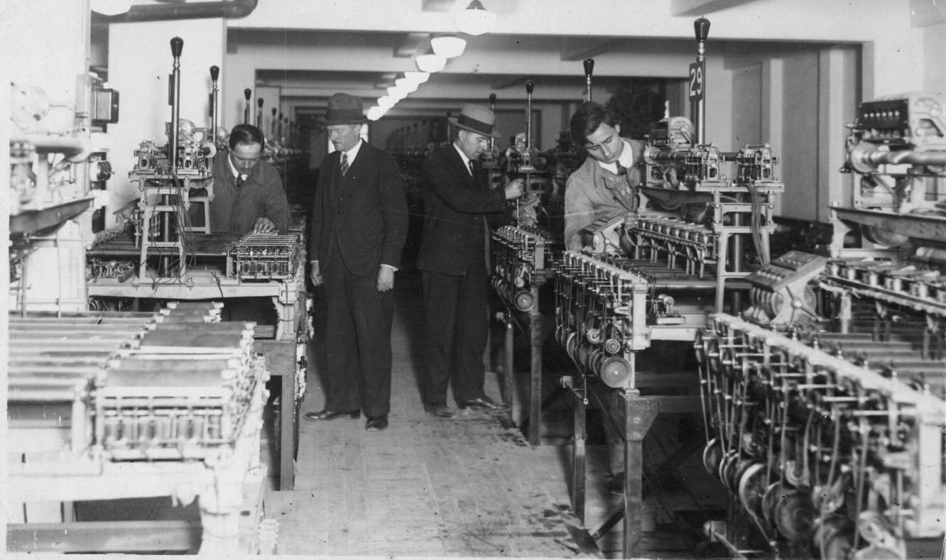
I have provided the above image here to give an idea of what the title of this page refers to in mentioning this is one of many adders at Longchamps. This is an image of the Longchamps Machine Room which houses the Julius Tote central processing system. Have a look at the light poles on top of the adders and follow them into the distance of the image to get an idea of the size of this system. These were behemoth machines. On the second adder in the right hand row, the light pole runner number on the top of this adder is legible bearing the number 29. This means this adder is totalling the investments for runner number 29 which also means that this is the 29th adder. There are as many adders as runners in the race for the Win pool and this is doubled to support the Place pool. There is an additional two adders to calculate the grand totals for Win and Place pools. There will be more adders in the machine room behind the photographer.
When looking at any Julius Tote adders like these ones, it is interesting to consider that you are looking at a piece of ancient equipment capable of parallel processing, which is a modern computing concept. This old system through the Julius Adders, could do something that the digital computers I introduced on the Brisbane racetracks that replaced these Julius systems could not, parallel processing. I was often reminded of this by the staff I inherited who used to work on the Julius totes. If two or more or all of the escapement wheels in any of the eleven constituent shaft adders in any of the complete adders shown above are activated at the same instant by their associated scanners (Time division multiplexers) due to the scanned TIMs (Ticket Issuing Machines) having transactions pending on the runner the shaft adder is totalling, then the multiple escapement wheel activations are instantaneously registered by the epicyclic gears in the adding shaft. Two of these eleven constituent shaft adders mentioned, can easily be seen one behind the other in the image at the top of this page sitting on the right hand side of the top of the bridge like section of the adder. The two storage screws, the rear one mostly obscured by the front one, can be seen running from the left hand side of their respective shaft adders to the left hand side of the complete adder.
My new computer totes, although being loosely coupled multiprocessors, were not capable of parallel processing. Each processor sequentially processed every bet and this transaction processing was first done by the master computer which then passed transactions to the slave computer for recording, albeit that this happened so quickly that it all looked like it was happening at once. The Julius tote shaft adders could record multiple bets instantaneously, which their replacement, digital computer based totalisator systems could not!