This history page contains a photograph which is one of several belonging to the photo gallery pages which are part of several pages relating to the invention of the world's first automatic totalizator in 1913 by George Julius, and Automatic Totalisators Limited the Australian company founded by George Julius to develop manufacture and export these systems.
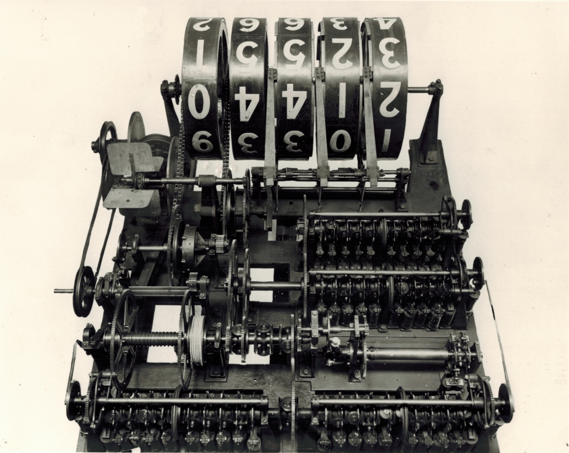
A 1917 Randwick Julius Tote Shaft Adder
This image shows a counter wheel electromechanical shaft adder. It was part of the central processing system of a large Julius Totalisator at Randwick Racecourse in Sydney, which commenced operation in 1917. In 2017 as I am making alterations and additions to this page, this adder is 100 years old! There are many of these in the machine room of a totalisator system. This one is the same model as the one in a video clip on the British Pathé Website to which there is a link in the Three more ATL systems in Asia/Links to other pages chapter of this website. The British Pathé Website indicates this type of adder was in use on a Sydney racetrack and indicates a year, 1927. An Automatic Totalisators Limited promotion document titled The PREMIER (JULIUS) AUTOMATIC TOTALISATOR, written in 1930, has an image of The Paddock at Randwick Racecourse. The annotation for this image reads: FIG. 3. "Paddock" Installation on the Randwick Racecourse, Sydney, N.S.W. This is the first all-electric "Premier" Totalisator built and installed in 1917, and still in operation. Another photo of this tote house is shown below in the image titled The Old Main Tote at Randwick 1917
More after the image...
Click on the image to go back to the Photo Gallery
There is no photographer's stamp on this photograph.
As there is no information written on or attached to this photograph, I started to investigate what system this adder belonged to. Two things are striking. With the number of escapements on this adder it belongs to a large system. Additionally it pre-dates the front end systems which made it possible to attach multiple TIMs (Ticket Issuing Machines) to each escapement wheel solenoid in the adder, as they multiplexed up to 16 TIMs onto a single escapement. As the 1917 Randwick system was the first of the electromechanical systems and was the system that led to the development of the front end systems, it is probable this adder belonged to the 1917 Randwick system. Additionally, as much was made of the 1917 Randwick system being the first totalisator to implement electrical elements, making it noteworthy and hence more likely to have been photographed may be a reason this photo exists today. If so, this contributes to the premiss that the adder at the top of this page belongs to the 1917 Randwick totalisator, as does the fact that it is of an older Julius Tote adder design. The successor to this system was a later generation Julius Tote installed in 1935 which postdates the information on the British Pathé Website which was published in 1927, so it will not belong to that system apart from which that totalisator system would have had the front end system implemented.
I can see a problem with attributing the actual Adder shown in the British Pathé Website page to the 1917 Randwick system. Although the British Pathé Website video clip is low resolution, it seems that although the adder is clearly of the same design as the one at the top of this page, it does not appear to have sufficient number of escapements to support the number of machines of the 1917 Randwick system. Other possible candidate tote systems for using this type of adder between 1917, the year of the first electromechanical Julius Tote as the adder in question is electromechanical, and 1927 when the video clip was made are Canterbury Park Racing Club, Rosehill Race Club, Victoria Park Race Club and the AJC at Warwick Farm. An argument against the adder in the British Pathé video clip, belonging to one of the Julius Tote systems at the above listed racetracks is that the Video Clip adder looks older to me than the 1917 Randwick system adder shown above, so it is unlikely to have been part of one of the installations following that of the 1917 Randwick tote system. Later evidence showed that the adder at the top of this page exactly matches a description from George Julius describing the 1917 Randwick adders.
I have stated that the adders being discussed are electromechanical. It can be seen in the image above that this adder is electromechanical. The electrical elements are the solenoids that trip the escapement mechanisms, visible below the adding shafts, as a result of receiving impulses from the TIMs. There are four adding shafts two along the near side of the adder and another two behind the right hand near side adding shaft. Additionally, an example of the previously mentioned noteworthiness of the 1917 Randwick totalisator system is in the nickname All-Electric Totalisator, or as the British Pathé website calls it the wonderful electric Totalisator. This 1917 tote was a big system, with 150 terminals and I consider it to be the world's first large-scale, on-line, real-time, multi-user system.
I have presented the following commendation from the secretary of the AJC as it refers to the 1917 Julius Tote at Randwick. He mentions the TIMs (Ticket Issuing Machines) as well as the selling staff operating those TIMs. He refers to the TIMs as Automatic Totalisator Machines. These TIMs were all attached to a machine-room full of adders of the type shown in the image above. As this system catered for a maximum of 42 runners in a race, there would have been 43 adders in the machine room, one for each runner and another for the Grand Total. As there were three central processing systems in this 1917 installation, there must have been three of these machine rooms. C.W.Cropper Secretary Australian Jockey Club wrote the following on 22 July 1922:
I have pleasure in stating that the "Premier" Automatic Totalisator Machines, which were installed at Randwick Racecourse and are operated by your Company on contract under the supervision of the Club, and which were first used at the Club's Spring Meeting, 1917, have, since their installation, given complete satisfaction. Their accuracy is unquestionable and the rapidity with which tickets are issued by the experienced operators leaves nothing to be desired.
Below is an image of one of the "Premier" Automatic Totalisator Machines, or in contemporary terminology TIMs (Ticket Issuing Machines) or Terminals, that C.W.Cropper has mentioned. As previously mentioned, there were 150 of these supplied with the Randwick System.
A TIM used in the 1917 Randwick Tote system
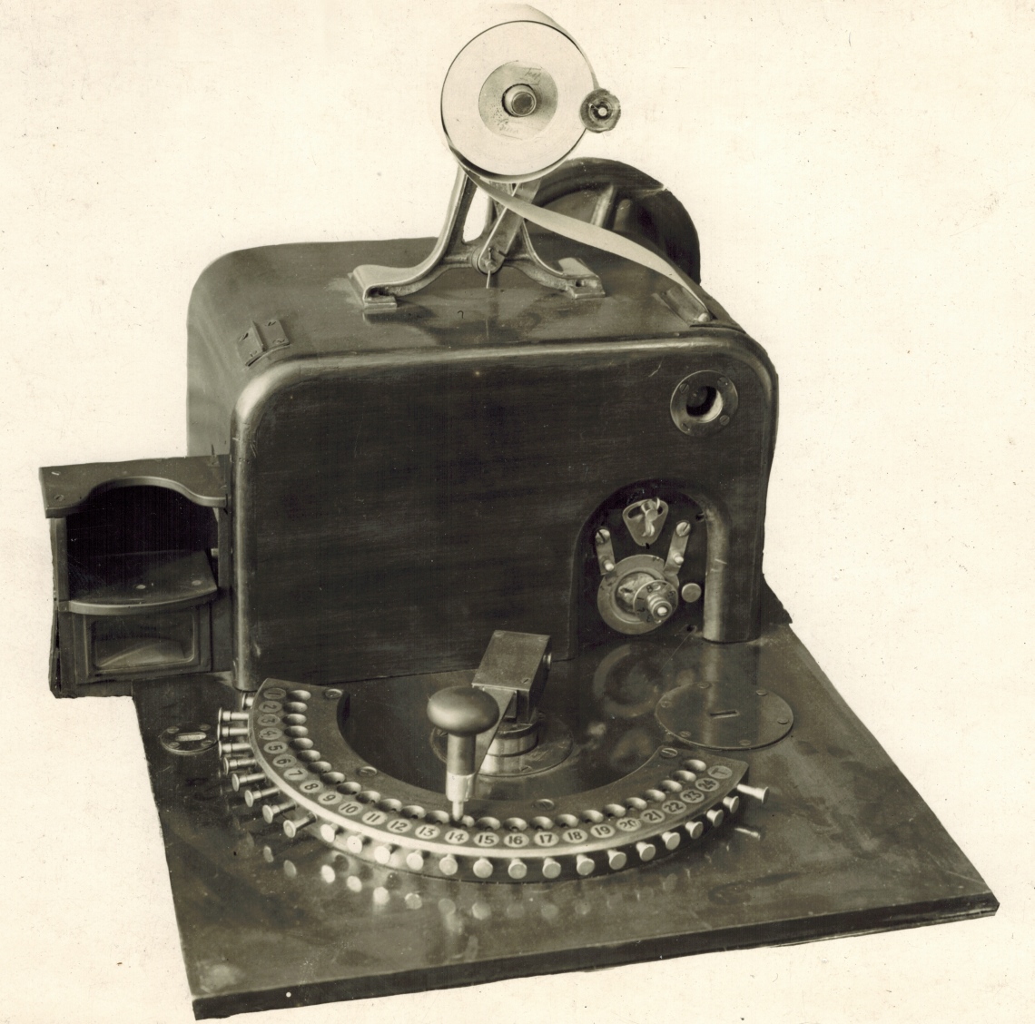
The second image after the one shown at the top of this page in the Photo Gallery of this website, shows a full sized version of the TIM shown above. To view this click on the image at the top of this page and select the image thumbnail of the second image below that one.
Having just mentioned the TIMs above, as shown in the image above and their connection to the adders, like the one shown at the top of this page, it is worth reiterating that although the 1917 Randwick system was the first of the electromechanical systems, it did not implement the front end systems, which were implemented in following Julius totalisators and adding that as a consequence, the 1917 Randwick Julius Tote adders only had one machine attached to each of the escapement wheels. The TDMs (Time Division Multiplexers) in these front end systems, which were invented by Automatic Totalisators Limited, were at the time called Distributors or Scanners. These front end systems were developed shortly after the 1917 Randwick system project and are mentioned in George Julius' Mechanical Aids to Calculation white paper written in 1920, which was presented to the Institution of Engineers Australia as part of a demonstration that same year. The demonstration system that was built and tested, which had the new front end system, was capable of supporting 1000 terminals and a sell rate of 250,000 transactions per minute. This transaction rate converted to the more familiar computer era measurement is over 4000 transactions per second and this was considered good during my tenure in the totalisator industry, which spanned over 30 years and was all spent working on computer based totalisator systems. Having mentioned the Institution of Engineers Australia, it is worth mentioning that George was an instrumental founder of that organisation.
The image following the one at the top of this page in the Photo Gallery of this website, shows the type of adder that was used in George's demonstration system for his presentation to the Institution of Engineers Australia. To view this click on the image at the top of this page and select the image thumbnail of the following image.
The Old Main Tote at Randwick 1917
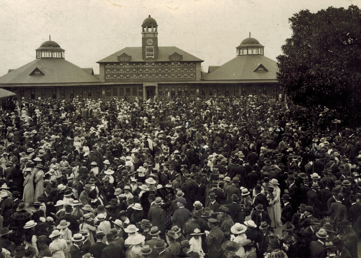
The above image shows the old Main Tote House at Randwick which was custom built to house part of the 1917 Julius Tote. The adders like the one in the image at the top of this page, were housed in the central upper level under the central clock tower. The counter wheels of these adders were placed so they were visible from the outside in the long horizontal slot like windows in this building which are aligned in 3 rows of 14 adders. Three rows of fourteen means there are 42 adders one for each of the 42 possible runners in a race mentioned previously. Below the clock in the central tower, there are two indicators. The upper one that looks like the taller of two black oblong rectangles in a white frame, is a dividends indicator which is controlled manually. The lower one is the pool grand total indicator which will have the grand total adder sitting behind this window.
The Adder shown at the top of this page and the TIM shown in the following image, are examples of electromechanical computing on an industrial scale and are parts of this electromechanical large scale real time multi user system. By examination of the adder image, it is clear that this is a four shaft adder as there are four main adding shafts. There are two shafts side by side that span the width of the adder at the bottom of the image. Two more of these shafts can be seen one behind the other on the right hand half of the adder towards the rear near the large counter wheel display drum. There are ten escapement wheels and associated solenoids per shaft giving a total of forty escapement wheels and solenoids. The number of teeth on each escapement wheel determines the value of the bet recorded. The more teeth the lower the value. The rotation of every escapement wheel is added by the epicyclic gear train connecting the escapement wheels such that the rotation of the adding shaft at any particular point along the gear train is the sum of the rotation of the escapement wheel at that point and every other escapement wheel upstream from that point, away from the counter display wheels.
In the previous paragraph I have deduced from the image that this adder has forty escapement wheels and solenoids. George Julius adds to the belief that this adder is the type used at Randwick by confirming that the adders in the 1917 Randwick Julius Tote indeed had forty escapements, which I have referred to as the escapement wheels and solenoids. George's reference to this appears in his Mechanical Aids to Calculation paper and this reference follows:
This modification has very greatly reduced the amount of adding gear required in the machine, as in the new type four, or at most six, escapements perform the same duty as was previously performed by the forty escapements in the Randwick type of machine.
The modification George mentions above, is the introduction of the distributors which were time division multiplexers as mentioned previously.
Recently I was transcribing some minor segments of George Julius' paper titled Mechanical Aids to Calculation, which had originally been omitted, onto this website and discovered a paragraph that positively identifies the adder shown at the top of this page as belonging to the 1917 Julius Tote at Randwick. It describes the design of the adding shafts of the Randwick Adders, which perfectly matches the adding shafts in this adder. This alone is proof positive that the adder shown at the top of this page was of the type used at Randwick. The additional paragraph in George's paper, which is now included in the Mechanical Aids to Calculation chapter of this website about this paper, reads:
Until recently the adding gear has comprised an electromagnetic escapement and a corresponding epicyclic gear for each ticket-issuing machine; thus, on the large machine installed at Randwick there are forty selling-machines and the adding gear of each horse counter or numerator comprises forty sets of escapements and epicyclic gears arranged in four groups of ten. A central gear on each group of ten gives the added results of the issue of the ten selling windows, and these four sets of added results are again combined to give the sum total of the issues of the forty selling machines.
The image at the top of this page shows one of the adders, which George calls a horse counter or numerator, that belonged to what George refers to as the large machine installed at Randwick in the previous paragraph. The forty sets of escapements and epicyclic gears arranged in four groups of ten which George mentions are clearly visible in this image and are the four adding shafts with ten escapement wheels on each, as determined by visual inspection above.
The central gear that George mentions regarding each of the adding shafts, are clearly visible, the largest diameter circular wheel in the centre of all four adding shafts. George tells us the central gear gives the added results of the issue of the ten selling windows, which is the sum total of the angular displacement of each of the escapement wheels on each of the adding shafts.
Finally George refers to the sum total and informs us that these four sets of added results are again combined to give the sum total of the issues of the forty selling machines, which can be traced in this adder. The central gears of the two front adding shafts, drive an epicyclic gear in between the two shafts, which sums the angular displacement of these two shafts and the cog associated with this epicyclic gear transfers this rotation to a short adding shaft behind the front ones, in the second row of equipment.
The central gear of the two right hand rear adding shafts, are summed at the cogs on the left hand side of these shafts and this rotation is transferred to cogs on the left hand side of the adder via a short shaft extending left from the near side adding shaft. From there this angular displacement is transferred to the previously mentioned short adding shaft via cogs in the second and third rows of equipment.
The short adding shaft epicyclic gears sum the rotation of the two groups of two adding shafts and applies it to the Storage Screw to the left, which looks like a square threaded shaft between two large cog wheels, on the far left of the adder in the second row of equipment.
In conclusion this adder matches George's explanation exactly. This is indisputable evidence that the adder shown at the top of this page belonged to the 1917 Randwick Julius Tote. In the following extract from the same document George contemplates larger systems than the Randwick Julius Tote:
In considering the application of the equipment to meet very much greater demands, it was apparent that the very large amount of gearing required under what may be called the Randwick system would be very costly both to install and to maintain. A modification of the system has therefore been developed.
George has mentioned a modification to the system, which he then goes on to describe, however I will just mention it quickly as the modification has already been introduced above. The Randwick system led to the introduction of time division multiplexers called distributors, which greatly reduced the need for so many solenoids and escapements in the adders. This would eventually ensure that new systems are supplied with Time Division Multiplexers that Automatic Totalisators Limited invented, to make larger systems possible and keep costs down, eliminating the need for adders such as this 1917 Randwick Adder. As the 1917 Randwick system was the first of the electromechanical systems it is probable that there were only a few installations where this type of adder continued to be used if any. As previously mentioned, the British Pathé Website video footage shows this type of adder in use on an Australian Racetrack which appears to have fewer escapements than the Randwick adder, which could mean this one is part of a different installation. In conclusion, the adder shown at the top of this page was manufactured for the 1917 Randwick Totalisator system.
The Mechanical Aids to Calculation chapter of this website contains two extracts from George's white paper of the same name, which contain the complete content relating to the Julius Tote. To read this, click on the image at the top of the page to return to the Photo Gallery. Then Scroll to the bottom of the page and select the Go to the index button in the Navigation Bar at the bottom of the page. Finally, select the chapter titled Mechanical Aids to Calculation.
Note that there is a paddle wheel at the end of a shaft on the left hand side of the adder just below the counter wheels at the back. Mike Bell, an ex ATL Project Manager and Software Engineer informed me this is an inertia brake. The counter wheels are arranged as a decade counter each counter wheel rotates one digit after ten digits have been displayed in the counter wheel on it's less significant digit side. When they were operating the units counter wheel could have such rotational velocity that it appeared as a blur. This is well demonstrated in the British Pathé Website video footage. As betting is erratic there was significant stress placed on the mechanical parts. The worst case scenario occurs when the race begins. The betting activity goes from near its peak to nothing in an instant. Inertia prohibits machinery from stopping in an instant.This paddle, assisted braking by introducing aerodynamic drag, when the sell rate was rapidly declining. In addition, to control shock associated with inertia limited parts of the system, there is a device called a storage screw, which is well covered in other images of this photo gallery.
Briefly, the storage screw is a form of buffer memory which records transactions from the quick to accelerate adding shafts, and is read by the inertia limited parts of the adder which empty the buffer as they catch up.
Bob Moran has identified parts of the adder shown at the top of this page, during his investigation into the 1917 Randwick system. Bob is a mechanical engineer who has done much restoration work on Julius Totes for exhibition purposes, long after they ceased operation. Additionally Bob has retrospectively created engineering drawings of parts of the Julius Totes, which are superior to the ones the company that manufactured the Julius Totes produced. Bob has also created Julius Tote demonstration systems, which can be hand operated and demonstrate how they used to work. Bob has also created what he calls the Discovery Shed to inspire young minds and generate interest in Science Mathematics and Engineering.
Bob discovered that the horizontal tubular section with large cog wheels at both ends of it, on the left hand half of the adder, immediately behind the left hand adding shaft at the front of the adder, is a storage screw. This buffered the transactions from all the adding shafts, until the units counter wheel could catch up. The storage screw had a device which today, after the establishment of the electronics industry, is called a closed loop servo system associated with it. This ensured the units wheel did not suffer the shock associated with a sudden stop, as occurs when the betting is stopped at the start of the race, and instead was slowed before coming to a gentle halt.
Bob also identified the variable speed friction gear at the far left rear of the adder behind the paddle wheel brake. It consists of two wheels at 90 degrees to each other with the right hand wheel in contact with the left hand wheel and capable of moving in towards the centre of the other wheel or towards the rim of the other wheel. The right hand wheel is padded around the perimeter increasing friction between the two wheels, imparting motion from one to the other. The movement of the right hand wheel in and out effectively alters the gear ratio between them. This variable speed friction gear, is the means of implementing control in the closed loop servo system analogy.
Bob found another very important counterpart in the adder to the closed loop servo system analogy. Bob calls it the speed control lever and in the closed loop servo system this is where the feedback path alters the control input. It is somewhat hidden and runs between the left hand end of the storage screw shaft, where the position of the storage screw within the body of this device is sensed, and runs to the variable speed friction gear. A segment of it is best seen near the bottom of the adder, between the first and second horizontal shafts rearward of the storage screw shaft. The speed control lever crosses and runs beneath both shafts mentioned. These three shafts have a unique appearance to further identify them. The storage screw shaft looks like it has a raised helix on the surface of it, giving it the appearance of being threaded, which it is on the inside. The first horizontal shaft rearwards of the storage screw, looks square with longitudinal channels cut into it. The second shaft rearwards is a shorter, plain circular reduced diameter shaft.