More about this adder below the image.
Click on the image to go back to the Photo Gallery
The photographer's stamp on this photo reads: HALL & CO. Commercial Photographers 20 Hunter Street Sydney
More about this adder below the image.
Click on the image to go back to the Photo Gallery
The photographer's stamp on this photo reads: HALL & CO. Commercial Photographers 20 Hunter Street Sydney
The fifty Julius Tote Combined Shaft Adder and Indicator units mentioned were mounted on the machine room wall with the display window facing outwards where the public could read the runner total investments as well as the pool grand totals in the form of an indicator display board. This indicator display board can be seen in the image below, at the first floor level. The left hand side of the indicator below, relates to the Win Pool. Above the left hand indicator section is the word WIN. Below that to the right are the words GRAND TOTAL in smaller letters, that are difficult to read without enlarging the image and below them is the Win Pool grand total counter window. Below that again, there are two rows of Runner Total investment counter windows, with the runner numbers 1 to 12 above the first row and 13 to 24 above the second row of windows. Each one of these windows has a Combined Shaft Adder and Indicator unit exactly the same as the one shown in the image above installed behind it. At the ground floor level to the left of the centre of the building are the Win Pool windows containing the TIMs (Ticket Issuing Machines) for the Win Pool. This is all replicated on the right hand side of the Grandstand building in the image below for the Place Pool. There is a full sized version of the image below in the photo gallery of this website. To view this, click on the image above and scroll up slightly and select the image thumbnail of the Bombay Grandstand with associated text starting The Western India Turf Club Grandstand.
Western India Turf Club Grandstand in Bombay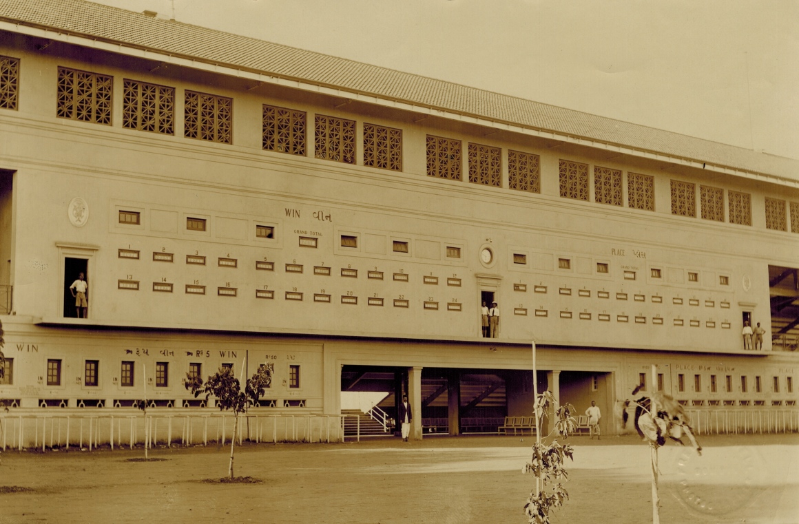
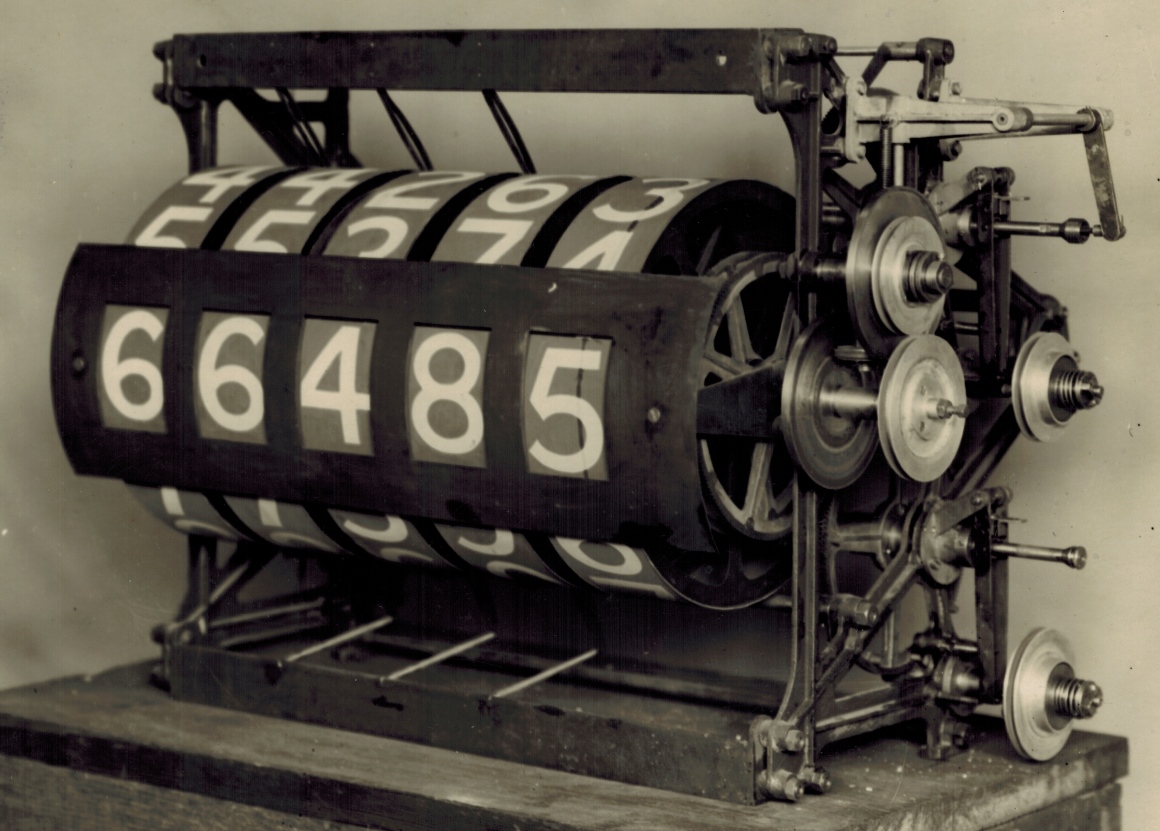
Back to the image at the top of this page. The adding shafts inside this Combined Shaft Adder and Indicator unit, with their epicyclic gear arrangement, escapement wheels and solenoids that are activated by ticket issuing machine pulses are at the back of this adder hidden from view. I have included an introduction to the adding shafts in the previous image of the photo gallery, that shows an image of the adder/indicator unit shown at the top of this page, from the rear. To read this, click on the image at the top of this page, scroll up one image thumbnail in the photo gallery index and select the image thumbnail above the thumbnail for the image at the top of this page.
As these adding shafts are an ingenious part of the Julius Totes, I will mention that there are better equipment photographs in this website that illustrate more clearly the mechanisms on these shafts, where I have provided descriptive information relating to these devices. To read about the workings of the adding shafts, there is a Photo Gallery page that I suspect will satisfy the most fervent curiosity about their engineering. To read it, click on the image at the top of this page and scroll down in the index to the heading Miscellaneous Images and select the image icon in that section of a Three Shaft Adder with the associated text starting with A three shaft adder viewed from the escapement end. If there is any remnant interest in the theory of how these adding shafts work, there is no better source of explanation than that provided by a White Paper titled Mechanical Aids To Calculation written by Sir George Julius himself, the inventor of these initial automatic totalisator systems. To read this white paper, click on the image at the top of this page and scroll down to the bottom of the loaded page and select the Go to the index button in the navigation bar at the bottom, then select the Mechanical Aids to Calculation chapter in the Firstly section of the index.
Having dispensed with the adding shafts, I will concentrate on the storage screw and in particular its control mechanism which George Julius refers to as a Variable Speed Friction Gear. Before proceeding however I would like to make a comment about the use of the word Storage in the name Storage Screw. I suspect this might be the first use of the word Storage, implying memory as it does in electronics and in particular digital computers. I have never seen an actual example of these early shaft adders like this adder/indicator unit, only photographs like the one at the top of this page. After many years of being fascinated by the concept of the Storage Screw and looking for an example of its control mechanism in all the equipment photographs, I concluded I would never see an example of George's Variable Speed Friction Gear. I was delighted when it finally dawned on me, whilst looking at magnified portions of photos of adders like the one at the top of this page, that the image at the top of this page has a Variable Speed Friction Gear on display, peering out from obscurity. EUREKA! I realised that there is no question about this being an example of a Variable Speed Friction Gear as George's name for it perfectly matches what is visible in the image at the top of this page. The storage screw has been described in the previous image page of the Photo Gallery so I will pick up the description of the Variable Speed Friction Gear from there. Neither of the two storage screws is visible in the view of the adder/indicator seen in the image at the top of this page, however the two storage screw position sensing rods can be seen extending to the right out of the tubular section of the storage screw, past the pulleys on the right hand side of the Adder/Indicator. The upper rod has a mechanism attached to the right hand end of it, that drives the Variable Speed Friction Gear mentioned in George's paper.
I have included an extract from George Julius' paper he presented to the Institution of Engineers Australia in 1920 here, as this extract relates to the storage screw and in particular the variable speed friction gear:
The movement of this screw is so arranged that it also controls a variable speed friction gear through which the counters are driven. During any period of acceleration in the issue of tickets, the screw is withdrawn in the nut faster than the counter operates, and this through the friction gear speeds up the counter, and the nut, in an endeavour to overtake the movement of the screw, and a condition of balance is ultimately established. If the issue of tickets is retarded or ceases, the nut immediately gains on the screw and brings it forward, thereby picking up all the stored-up records, and by means of the friction gear gradually slowing down the counter until when all the records are recorded, it quietly comes to rest. The rotation of the nut also is utilised to continually rewind the coil spring which operates the epicyclic gears, and thus ensure a steady driving effort on these gears.
First a quick explanatory note about George's description above. The screw he mentions is an internal screw inside the tubular part of the storage screw. The transactions from the Adding Shafts wind the screw along the internally threaded tubular part of the storage screw. The angular displacement of the screw in the tubular part of the storage screw represents the number of investments made on the adder. This is analogous to writing to a buffer memory. At the other end of the storage screw, which drives the counter wheels, the tubular part of the storage screw is wound in the opposite direction tending to move the internal screw back to its starting position. This is analogous to reading a buffer memory. Logically, the tubular part of the storage screw is what George refers to as the nut.
At the right hand end of the mentioned upper storage screw position sensing rod in the image at the top of this page, there is a lever projecting down from a mounting above, that has a hinged tip at the bottom end making contact with the right hand end of the storage screw position sensing rod. This is part of the control mechanism for the Variable Speed Friction Gear that George has described. This near vertical arm of the lever that is in contact with the tip of the storage screw sensing rod, that I will call the Storage Screw Position Sensing Arm, is affixed to its fulcrum rod at its upper end. This fulcrum rod is mounted between two horizontally projecting support arms attached to the right hand side of the Adder/Indicator frame. The near side of this fulcrum rod is affixed to another lever arm, that I will call the Friction Gear Positioning Arm extending to the left towards the frame of the adder and is totally hidden by the near side fulcrum rod supporting bracket. Due to the fact that the Storage Screw Position Sensing Arm and the Friction Gear Positioning Arm are fixed at right angles to each other through the fulcrum rod, small arc rotations of the fulcrum rod caused by the horizontal motion of the storage screw position sensing rod through the Storage Screw Position Sensing Arm, is converted to vertical motion at the left hand tip of the Friction Gear Positioning Arm. This Friction Gear Positioning Arm, which is hidden in the view of the adder at the top of this page, is visible in the previous image of the photo gallery. To view this, click on the image at the top of this page and scroll up at least one image thumbnail in the Photo Gallery Index and select the image thumbnail above that for the image at the top of this page.
Now returning to the near support arm for the fulcrum rod at the top right part of the adder, a bulging vertically oriented cylinder like section can be seen that is part of the arm's metal casting, close to the left hand end of it. A rod can be seen in the image at the top of this page, descending vertically down from this cylindrical section in the support arm, which fixes the rod to the adder/indicator chassis. Also, to the left and parallel to this descending rod there is what I think is part of a long coil spring, descending from an attachment point on the left side at mid height level of this cylindrical bulge on this support arm. Almost all of the descending rod, missing only an insignificant part of the top bit, can be seen in the previous image of the Photo Gallery. This rod descends to a position close to the rear side of the bottom of a large metal disk mounted immediately behind the highest pulley on the right hand side of the Adder/Indicator in the image at the top of this page. A longer section of the parallel long coil spring mentioned can also be seen in the previous image of the Photo Gallery. In the view of the bottom of this descending rod seen in the previous image of the Photo Gallery, a substantial metal collar is seen mounted on the rod near the bottom, that is capable of being moved up and down the fixed rod. In another photograph not presented on this website of the adder/indicator shown at the top of this page, the end of the Friction Gear Positioning Arm, where the horizontal movement of the Storage Screw Position Sensing Rod has been converted to vertical motion can be seen. At the tip of this Friction Gear Positioning Arm where the vertical motion takes place, a hinge is visible in this other image, with an attached descending long black arm also attached to it. In the previous image in the Photo Gallery, this black arm can be seen on the near side of and overlapping the right side of the descending rod. The descending arm is attached to the mentioned collar that travels vertically on the descending rod and in the image is near the bottom of the rod. It is clear that the black arm attaches the Friction Gear Positioning Arm to this rod mounted collar and consequently is the means of moving the collar up and down the vertical rod. Also in the previous image of the Photo Gallery view of the bottom of the descending rod, a small part of the friction gear wheel can be seen slightly behind the collar and just above the bottom of the collar on the descending rod. This is a dark section of the adder/indicator image and no further details are discernible, however it is clear to me that the spindle of the friction gear wheel is connected to the collar on the descending rod and that both move up and down the rod together. The long coil spring parallel to the descending rod probably applies some upward force to assist the storage screw position sensing rod in raising the combined collar and friction gear wheel assembly.
On the right hand side of the adder in the image at the top of this page, there are four pulleys visible. The highest of these pulleys has a metal disk attached close behind it. The pulley immediately below the first also has a metal disk attached to its spindle with a gap between the two, where part of the spindle which they are both mounted on is showing. The bottom of the top metal disk protrudes into this gap, overlapping the top of the lower disk. Between these two metal disks in the overlapping area, suspended directly above the visible part of the spindle of the lower disk and partially obscured by the upper disk, a wheel oriented at 90 degrees to the two metal disks can be seen. This wheel contacts the visible side of the lower disk and the back side of the overlapping higher disk. Again, Eureka -- we have found it! This wheel in conjunction with the two metal disks it contacts is George's Friction Gear in his name for the storage screw control system Variable Speed Friction Gear. This wheel transfers the motion from the lower disk, that is attached to what I think is the main drive pulley for the whole adder/indicator unit, to a driven shaft associated with the upper disk and its associated pulley. From now on I will refer to these two disks as gear disks for obvious reasons, despite the fact that they do not look like conventional gears. This friction gear wheel is not only capable of rotation around its vertical spindle, but the whole wheel and spindle assembly can also be raised and lowered by the control system. This raising and lowering of the friction gear wheel implements the Variable Speed part of Georges Variable Speed Friction Gear name. This vertical motion of the friction gear assembly is confirmed by the shiny section of the lower gear disk where the friction gear wheel has been scrubbing the metal gear disk. You can gauge the range of vertical travel of the friction wheel by the width of the shiny scrubbing band. This friction gear is not a conventional gear in the sense that it has meshing teeth to transfer motion, instead as the name implies it uses friction to transfer the motion of the drive gear disk to a transfer friction wheel and from the other side of the friction wheel to the driven gear disk and it does transfer motion at variable gear ratios resulting in variable speed of the driven gear disk. The vertical motion of the transfer friction wheel gives different gear ratios as it moves up and down. Any vertical movement of the transfer friction wheel moves it closer to one of the disk spindles and further away from the other disk spindle reducing the effective diameter of one disk while increasing the effective diameter of the other.
Let's examine the limits of vertical motion of the friction gear wheel in the image at the top of this page, starting with the friction gear wheel at the bottom of its range of travel, that is clearly defined by the bottom of the shiny band above the spindle of the bottom gear disk. This is the closest the friction gear wheel gets to the centre of the bottom gear disk and this position corresponds to the closest point to the perimeter of the top gear disk, representing the most geared down position of the friction gear wheel imparting the least angular velocity to the driven top gear disk. Note that this is about the position of the friction gear wheel or transfer friction wheel was in when the photograph shown in the image at the top of this page was taken. With the friction gear wheel at the upper limit of its travel, that is the top of the shiny band above the spindle of the bottom gear disk, it is at its nearest point to the perimeter of the driving bottom gear disk. It is also at its nearest point to the centre of the driven top gear disk representing the maximum geared up position, imparting the most angular velocity to the driven top gear disk. There are a couple of features of this friction gear that have occurred to me since I started thinking about it. First in the previously mentioned more commonly known meshing teeth cog type gears, a gear change simplistically only requires changing one of the gear wheels to change the gear ratio. With the friction gear, any given vertical movement of the friction gear wheel is like changing the diameter of both gear cogs at the same time, one increasing and the other decreasing, amplifying the gear ratio change. In other words for the variable speed friction gear, the effective diameters of the gear disks change in opposition to each other, when the friction gear wheel is raised or lowered. Second, with the variable speed friction gear method, there is no need to consider synchronising the meshing process when changing gears.
It is interesting to note that in the vicinity of the friction gear wheel, the two gear disk surfaces that the transfer friction wheel is in contact with, are travelling in opposite directions. However as in the case of the bottom gear disk this vicinity is above the spindle and in the case of the top gear disk it is below the spindle, both gear disks are actually rotating in the same direction.
I find it curious how many analogies there are between these electromechanical Julius Totalisators and modern day electronics as well as computer engineering, a strong one of which exists here. The sensing of the position of the internal screw inside the tubular part of the storage screw and the feedback path controlling the rotational velocity of the body of the tubular part or unwinding section of the storage screw, as a function of the screw position is what in the electronics age would be called a closed loop servo system. The sensing for the feedback loop is done at the storage screw position sensing rod which provides acceleration or deceleration information as appropriate when the storage screw is in the vicinity of its rest position. The feedback path is the path of levers that start at the storage screw position sensing rod and ends at the control section with the raising and the lowering of the friction gear wheel.