This history page contains a photograph at the top of the page, which is one of several belonging to the photo gallery pages, which are part of several pages relating to the invention of the world's first automatic totalizator in 1913 by George Julius and Automatic Totalisators Limited, the Australian company founded in 1917 by George to develop, manufacture and export these systems. This is a small part of a mechanical computer long before the invention of electronic computers. It is an Electromechanical Shaft Adder which was part of a demonstration system.
Early large system adder - part of a Mechanical Computer
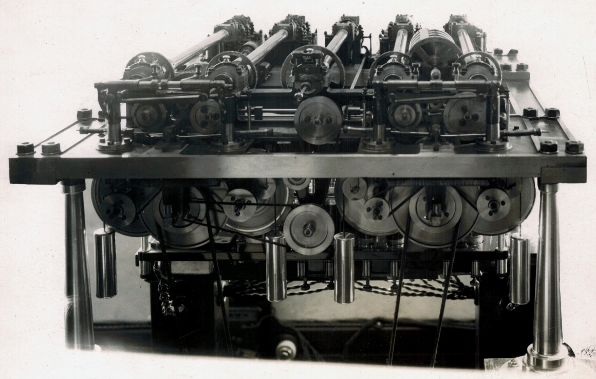
This is an image of an early large system adder. I deduce that it is early, as, although it is clear that it has electrical elements, it still has a foothold in the purely mechanical era, as parts of it are driven by weights. Four of these can be seen as long cylindrical shiny metal objects, suspended on the near side of the adder dangling below the mass of pulleys. One weight is on the inner side of each of the two front supporting legs with another two near the centre of the adder. The electrical elements are not on display in the image below as they are at the rear of the adder, however twisted pair wires can be seen dangling from underneath the adder in the lower part of the image. The adding shafts are at the rear of this adder, at the far end of each of the five long tubular sections extending from the rear to the front, which are devices called Storage Screws. The escapement mechanisms in the adding shafts are activated by solenoids which receive electrical impulses from the ticket issuing machines, delivered by the twisted pair wires seen dangling under this adder. The adding shafts, solenoids and wiring are visible in the top adder in the image below titled Page 4 Straight Betting but not in any detail due to the low resolution. The storage screws are a mechanical form of memory. As the Julius totes became electromechanical in 1917 and as this adder is electromechanical it was not constructed prior to that year. The earliest of the large Julius totes and the first electromechanical one was for the AJC (Australian Jockey Club) at Randwick in 1917, which was a stand-out system supporting 150 TIMs (Ticket Issuing Machines).
More after the image...
Click on the image to go back to the photo gallery
There are no photographer's markings on this print
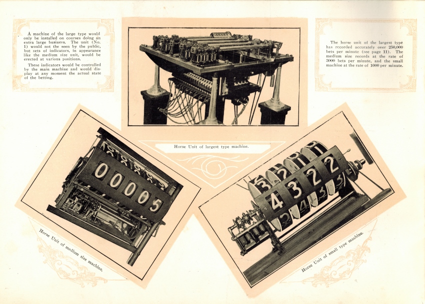
I have an original Automatic Totalisators Limited booklet titled Straight Betting. On page four of this booklet, I found three low resolution pictures of adders, as shown in the first image below. The top adder picture shows the exact same type of adder as the one in the image above, from a perspective at the left rear of the adder in the image above. This top adder picture in the image below has the caption Horse Unit of largest type machine. The bottom left picture in the image has the caption Horse Unit of medium size machine. and the bottom right picture has the caption Horse Unit of small type machine. The name Horse Unit refers to the adder. The note inside the top left text box in the image below, to the left of the "largest type machine" image reads:
A machine of the large type would only be installed on courses doing an extra large business. The unit (No. 1) would not be seen by the public, but sets of indicators, in appearance like the medium size unit, would be erected at various positions.
These indicators would be controlled by the main machine and would display at any moment the actual state of the betting.
The note in the top right text box in the image below, on the right hand side of the "largest type machine" reads:
The horse unit of the largest type has recorded accurately over 250,000 bets per minute (see page 11). The medium size records at the rate of 3000 bets per minute, and the small machine at the rate of 1000 per minute.
The image at the top of this page thus shows the "horse unit" (or adder) of the largest type. Horse Unit was a name applied to adders which were totalling investments on individual runners in a race and distinguished these adders from adders, which were calculating pool grand totals. Page 11, mentioned above, goes into technical details of the workings of the Adder, and one sentence states:
A machine has been manufactured and shown in Sydney that records bets up to 250,000 per minute.
I immediately recognised this statement which definitively identifies the adder shown above as being part of a demonstration to the Institution of Engineers Australia in 1920. George Julius, the inventor of the world's first automatic totalisator and founder of Automatic Totalisators limited, wrote a white paper about a totalisator system that had been built and tested in Sydney in 1920 which was capable of supporting 1000 terminals and a sell rate of 250,000 transactions per minute. George presented this paper titled Mechanical Aids to Calculation to the Institution of Engineers Australia on Thursday May 13th 1920. The adder in the image above was part of the demonstration system which was part of this presentation. The content from that paper, relating to this totalisator system is presented on this website in the Mechanical Aids to Calculation chapter. It is interesting to note that George Julius was an instrumental founder of the Institution of Engineers Australia and a President of that Institution.
Page 11 of Straight Betting also contains the following Paragraph:
In order that the various horse counters and the grand-total counter in the totalizator may be capable of quickly recording sales, no matter whether the majority of the sales are on one horse or divided amongst a number, each recording counter is equipped with a variable speed gear, controlled by a relay device, which automatically adjusts itself to the speed of betting, thereby getting over the difficulty of sudden stopping or starting of the large counter wheels, and thus ensuring that each counter can meet the demands of the betting quietly, and without shock, within the limits of the speeds for which it has been designed and installed.
I find the above paragraph very interesting, identifying analogies between this electromechanical computing and electronic computers. As previously mentioned the Storage Screws which were a mechanical form of memory long pre-dated electronic storage devices which are an integral part of digital computer systems. The name Storage Screw is possibly the first use of the word storage to imply memory. Equally, the system that controls the storage screw, part of which is described in the paragraph above is analogous to what nowadays is called a closed loop servo system. The relay device mentioned in the previous paragraph, as utilised in the adder in the image above, is not the electronic relay we think of these days, except for higher voltage applications. It is an open glass container with mercury in it, into which electrodes are immersed, the immersion being controlled by the feedback path of the closed loop servo system. I am attempting to discover more about how these relay devices functioned to control the variable speed gear, as mentioned in the above paragraph. I suspect these relays did not purely work as a switch, but as a variable resistor as well, dependent on the level of immersion of the electrodes.
Page 4 Straight Betting
The image above, as well as the rest of the Straight Betting booklet, is a historic example of artistic company product promotion in the early 1920s. Low image resolution was probably normal back then.
Thanks to Bruce Rutter, who held multiple management positions with Automatic Totalisators Limited finally becoming General Manager, for giving me his copy of Straight Betting. Although this booklet is elegant with an ornate cover, it seems to be a pre release version of it. There is fountain pen writing on the front cover which reads Mr Raymonas with memos inside written below. The text has deletions and additions marked in it, some in pencil and others in fountain pen.
In George's paper titled Mechanical Aids to Calculation, he makes two references to the Randwick system, which as it was written in 1920 refers to the 1917 installation. Firstly George relates that expanding the Randwick system to greater demands would be very costly to maintain and install. Secondly George relates that the adding gear with this new system is greatly reduced, as four or six escapements can now do the same as forty escapements in the Randwick machine. In other words, it was contemplations of systems larger than the 1917 Randwick system that led to the development of Time Division Multiplexers (TDMs) allowing multiple TIMs to be attached to each of the escapement solenoids. The impact of this is evidenced by the fact that, although the adder shown at the top of this page, which is an adder from the new system George mentions, is capable of supporting many more terminals than the 1917 Randwick adders, it has less than half the escapements in its adding shafts than those of the 1917 Randwick adders. I now realise that the TDMs which are an essential element of this and all following electromechanical Julius Totes, date back to at least 1920, which is much earlier than I expected. George and employees of Automatic Totalisators Limited did not call these multiplexers TDMs they were known as distributors and later scanners. The reason for this is that it had to wait for the electronics era for the name TDM to become common.
George's comments I mentioned above appeared in his white paper titled Mechanical Aids To Calculation and extracts of his two comments follow, so you can read them in his words:
In considering the application of the equipment to meet very much greater demands, it was apparent that the very large amount of gearing required under what may be called the Randwick system would be very costly both to install and to maintain. A modification of the system has therefore been developed, and may be briefly described as follows :-
In practice each issuing machine should be run at such a speed as will allow of the printing and issuing of tickets at the rate of 100 per minute, this being the maximum speed required. It has been found, however, that the electro-magnetic escapements can be installed to accurately pick up and record impulses at more than ten times this speed. The latest machines have therefore been constructed with one electro-magnetic escapement and epicyclic gear for each eight or ten ticket issuers. In this arrangement, however, allowance has to be made for the fact that the ten-ticket issuers may all issue tickets simultaneously on the same horse. Each issuing machine therefore is equipped with a device which stores up the impulse as soon as the machine starts to print a ticket, and this stored-up impulse is picked up by a distributor and passed on to the electro-magnet at a, speed that is slightly greater than the maximum speed of the issuing machines. Thus, if the ten issuing machines simultaneously start to issue a ticket on the same horse, during the issue of these tickets, the distributor picks up the ten impulses and delivers them in sequence to the electro-magnetic escapements. In such a case the electro-magnetic escapement would make ten beats in the time occupied by a selling machine in printing and issuing one ticket.
This modification has very greatly reduced the amount of adding gear required in the machine, as in the new type four, or at most six, escapements perform the same duty as was previously performed by the forty escapements in the Randwick type of machine.
George has mentioned the issuing machines above and their connection to the adders. The issuing machines became known as TIMs or Ticket Issuing Machines. The company document titled Straight Betting makes reference to the connection of the issuing machines that are installed in selling windows, to the adders in the central tote processing system of that era. It reads:
Such selling windows may also be located anywhere, as required. They can be placed in the building which contains the Totalisator, or may be a mile, or ten miles away. The only limitation to the location of issuers at a distance from the Totalisator itself is the question of minimising the amount of electrical wire required. The normal voltage used in all these machines is 110 volts, direct current, and the wire used to connect the selling machines with the Totalisator is 1/18, 600 Megohm grade insulated wire.
Finally, George's paper refers to a unit built to meet the condition of betting on the largest French racecourses, which refers to a system utilising the type of adder shown at the top of this page.
This becomes of great importance in considering large equipments. A unit has recently been built to meet the conditions of betting on the largest French racecourses. On such courses it is necessary to allow for the installation of at least 600 selling machines, and the counters may be required to record the issue of a million tickets in half an hour.
After seeing the adder shown in the image at the top of this page from the opposite end, as seen at the top of the image above, it became obvious to me that this adder could be the basis for the Longchamps adders which were later developed for this French project which was installed in 1928. The constituent 5 shaft adder assemblies and their associated storage screws visible on top of this adder shown at the top of this page, look very like the ones in the lower section of the Longchamps adders, although it is clear that this adder pre-dates the Longchamps adders which are considerably larger.
The complete Julius tote central processing system is large, requiring a sizeable machine room, as it consisted of many of these adders along with other required equipment and each of these large adders has a table arrangement to support it as seen in the above image at the top of this page. The machine room can be thought of in modern parlance as a mechanical computer room. On the subject of the machine room, the image below of the Longchamps machine room titled Similar to Figure 16 gives an idea of the amount of equipment, particularly when looking at the runner number posts on top of each adder disappearing into the distance, keeping in mind there are more adders behind the photographer.
I find this adder particularly interesting as it is so ornate particularly the legs of the table framework that supports it. Having discovered this adder was part of a demonstration system this explains why it looks so ornate. I have often felt that engineering and technology products have an artistic element to them. They often are visually attractive imparting to them an artistic quality. It is an additional bonus to think that these attractive artworks were technology devices performing a function. In the case of much of this Julius Tote equipment when looking at these artistic pieces, it is additionally interesting to contemplate that they had been functional for so long, usually decades and in some instances almost half a century and in one known case, the Caracas system, the full half a century. To my mind a lot of Engineering Drawing has an artistic quality as well.
The five tubular shaped devices on the top of the adder extending from the rear to the front, as previously mentioned, are called storage screws, a mechanical form of memory. The function they perform qualifies them as, what in the computer era is called, buffer memory. They remember transactions recorded by the high acceleration adding shafts at the rear of the adder and transfer them to the inertia limited parts of the system at the front as they are able to catch up. The electronic counterpart to the mechanical device, consisting of the storage screw and the equipment sensing the position of the screw itself when in the vicinity of its rest position, the feedback path and the control section, as previously mentioned is a closed loop servo system. This system is required to accommodate the momentum of the inertia limited parts of the system so they can be slowed down and brought to a gentle stop or be allowed to temporarily lag behind during periods of acceleration. The rods extending from the centre of the near side of the tubular bodies of the storage screws, in the image at the top of this page, are part of the screw position sensing system. The storage screws are dealt with in more detail in other images in the photo gallery.
Following is an extract from a company document titled The PREMIER (JULIUS) AUTOMATIC TOTALISATOR, which is the ninth extract and immediately follows on from the previous extract from the document. It relates to the Julius Tote Shaft Adders, referred to as Adding Machines or Adding Units in this extract. To read the previous extract, click on the image at the top of this page, scroll down to the bottom of the page and select the Next page option in the Navigation Bar. Then scroll down in the photo gallery index to the heading Ticket Issuing Machines (TIMs) and select the image thumbnail below the heading with associated text starting The type of TIM in use at Randwick Racecourse in 1917.
Adding Machines.
The adding units total all the bets made, almost as quickly as tickets are issued by the ticket issuers, the maximum time that may elapse between the instant of printing a ticket and registering its sale being less than two seconds, even during very heavy betting periods. THESE UNITS ARE CAPABLE THEREFORE, OF RECORDING, PRACTICALLY INSTANTANEOUSLY, ALL THE TICKETS SOLD BY ALL THE ISSUERS, EVEN SHOULD SUCH ISSUERS ALL ISSUE A TICKET ON THE SAME HORSE IN A RACE AT THE SAME INSTANT. One "adding unit" is provided in any totalisator installation to total the investments on each horse, so that there are as many adding units at work as there are starters in the race. In addition, a further, and usually a somewhat larger, unit is installed which automatically totals the whole of the investments on the race--that is to say, its record is the sum of all the records on the various horse adding units.
In small installations, as before mentioned, the adding unit and the indicator are as a rule combined, particularly where independent auxiliary indicators are not required, but on large installations the adding unit is entirely distinct from the indicator and may be installed in any suitable machine room, far removed from the indicators, should such be found desirable. In Fig. 15 a view is given of the largest individual adding unit of the Premier type yet built, and this unit, which is installed in Longchamps Racecourse, Paris, is of very much greater capacity than any other unit in use, whether of the "Premier" or of any other type, and in Fig. 16 a view of a group of such adding units is shown.
Figure 15 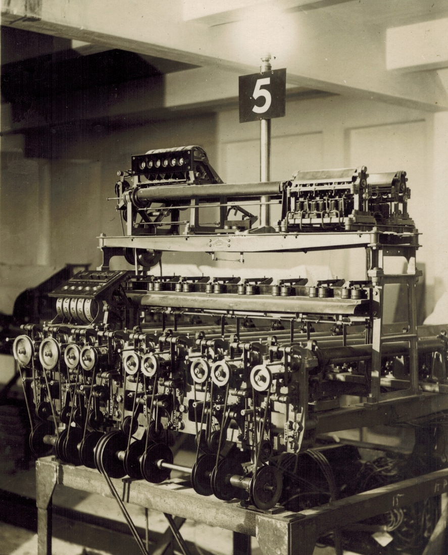
The above image is the same as Fig. 15 in the company document which has the associated text: "Premier" Totalisator Adding Unit installed at Longchamps. Paris. Note that the adder in the image above is much more modern than the one shown at the top of the page. This adder has no driving weights. This is a reduced image with the full sized version in the photo gallery, several images below the entry for the image at the top of this page.
Similar to Figure 16 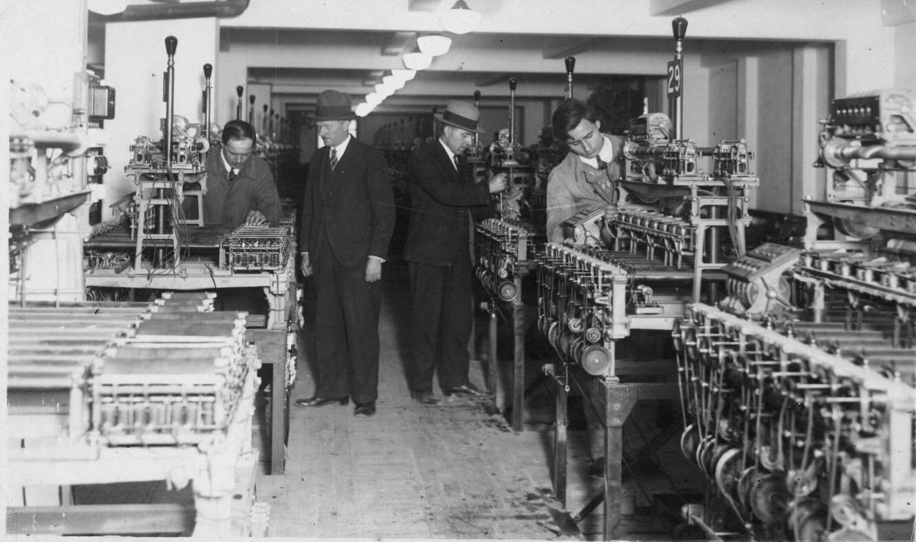
The above image is similar to Fig. 16 in the company document, the main difference being that the one in the document has no people in it. The document has the following associated text: Group of "Premier" Adding Units at Longchamps. Paris. This is a reduced image with the full sized version in the photo gallery also several images below the entry for the image at the top of this page. Click on the image at the top of this page to go to the photo gallery directory.
The image above shows a major part of the mechanical computer referred to in the title of this page. You can see the shaft adders extending into the distance to the far wall and there were adders behind the photographer as well, as the nearest runner adder number visible is 29 on the post above the second adder from the right hand side. This system supported 42 runners, requiring 42 adders for the Win pool and another 42 for the Place pool. This is an interesting historic point in that all the totalisators I worked on, mainly in Australia which were all computer based, had a maximum field size of 24. As the functionality was implemented in software, this limit was a configurable variable set at build time, but the systems I worked on were built with this set to 24. Back to the extract:
Where units of this capacity are used, independent indicators are required to display to the public the progress of the betting, and Automatic Totalisators Limited can supply indicators of various types as more fully described on Pages 16 and 17. In smaller installations a combined adding and indicating unit is used, and this type has been installed on many Racecourses.
Such a unit is shown in Fig. 17, the machine being so arranged that the numbers displayed on the front of the equipment are made visible to the public through suitable windows in the totalisator building. A group of such units, is installed on the West India Turf Club's Course, in Bombay, is shown in Fig. 18.
Similar to Figure 17 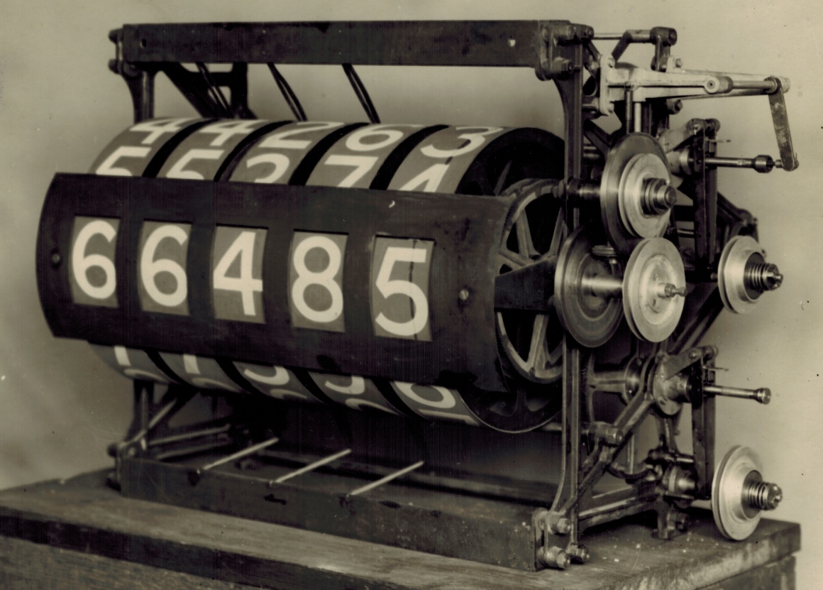
This image is very similar to the one in the company document and as Fig. 18 in the document shows the West India Turf Club's Course, Bombay system utilising these units, it is appropriate that the unit in the above image also belongs to that system. The annotation in the company document for this unit is: Combined "Premier" Adding and Indicating Unit for displaying numbers of Tickets sold as installed on various Racecourses. This too is a reduced image with the full sized version in the photo gallery a few images below the entry for the image at the top of this page. Back to the extract:
A simpler type of "Premier" equipment has recently been perfected, particularly suitable for smaller racecourses, and in these machines results are displayed by means either of dials and moving pointers or by a "barometer" type of Indicator, either of which system will inform the public quite sufficiently closely regarding the progress of the betting, whilst at the same time an exact count of the number of bets on each horse is recorded on a small counter on the unit itself, from which dividends can be calculated. Such a unit is shown in Figs. 19 and 20, and Fig. 19 shows in particular the lightness and compactness of this equipment, which is capable of recording all sales made on as many as 48 selling machines.
All Premier adding units are equipped with safety devices, which prevent errors in the recording of the betting should any unexpected failure of the mechanism occur, either mechanical or electrical. Such protective devices operate in such a way as immediately to stop the betting on any ticket selling machine where the record of such betting is not being correctly transmitted to and recorded by the adding unit. WITH THE PREMIER EQUIPMENT, THEREFORE, NO TICKETS CAN BE ISSUED WITHOUT ACCURATE AND PROMPT RECORDING BY THE ADDING MACHINERY.
As previously described, Premier equipment is now available, and is, in fact, in use by means of which the result of the betting can be displayed to the public in terms of the "expected dividend" or "odds" on the horse, in place of the more usual and older method of recording only the "number" of tickets sold.
The next extract from this company document, which immediately follows on from this extract, is below the entry for the image at the top of this page in the photo gallery under the heading Miscellaneous Images. To read it, click on the image at the top of this page, scroll down in the photo gallery index to the previously mentioned heading and select the image thumbnail with associated text starting The world's first Odds Computer. It finishes off the Adding Machines section and continues with the start of the Indicators section.