This page contains a photograph which is one of several belonging to the photo gallery pages which are part of several technology and company history pages relating to the invention of the world's first automatic totalizator in 1913 and Automatic Totalisators Limited, the company founded to develop, manufacture and export these systems.
Electronic Totalisators Brochure Courtesy Chris Robertson
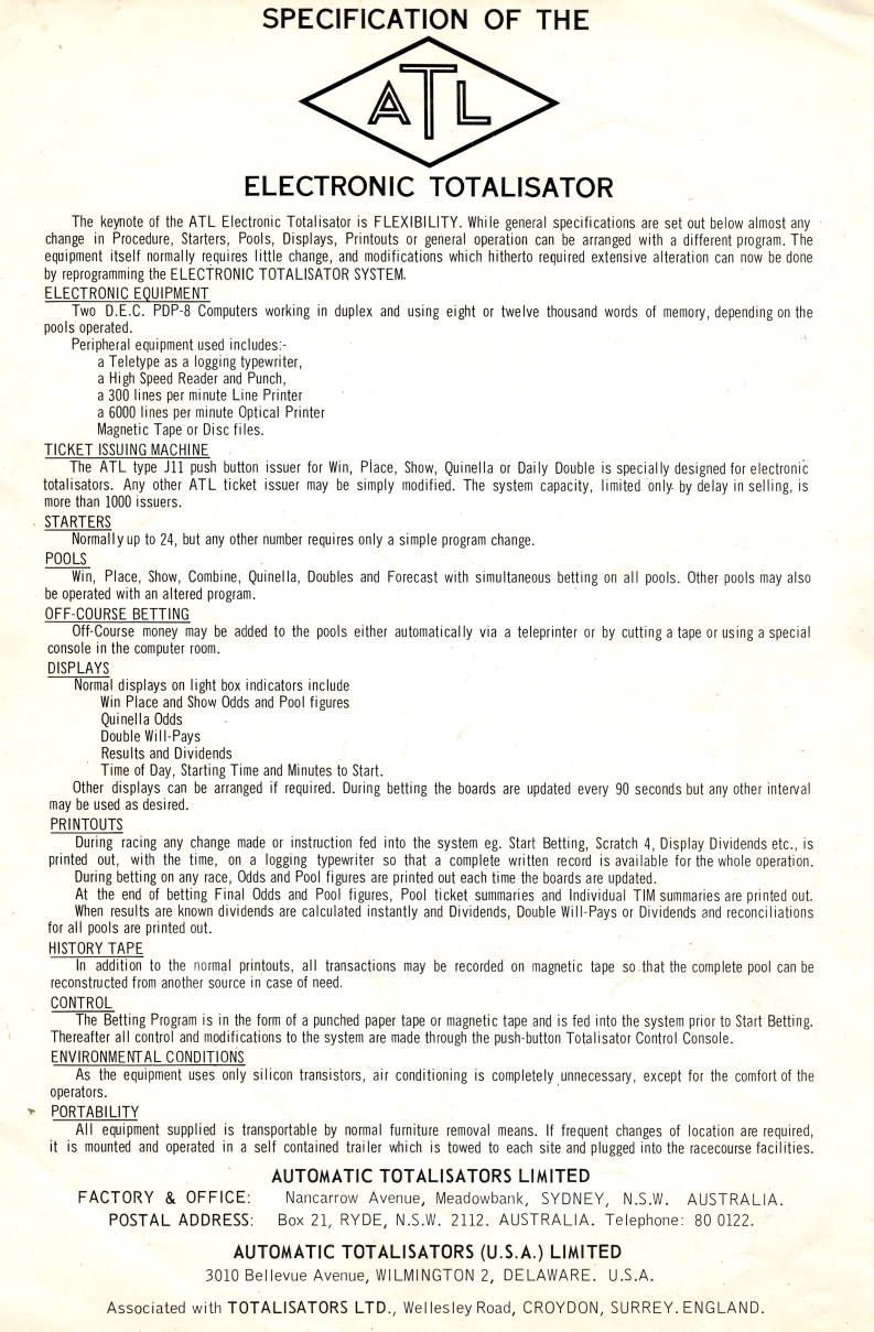
These images show the front and back of an Electronic Racecourse Totalisators ATL Product brochure in the form of an A4 size card. This and other cards like it on this website were provided by Chris Robertson, an ex customer of the company and an expert on its products and installations around the world. This brochure was probably produced in the 1960s. More below the images...
Click on the image to go back to the photo gallery
This is the front of an Automatic Totalisators product promotion card
Click on the image to go back to the photo gallery
This is the back of an Automatic Totalisators product promotion card
I recall using the type of paper-tape shown on the front of this brochure as a student and also during my early work at ATL. For any software developers reading this note the memory capacity of these systems, under the heading ELECTRONIC EQUIPMENT in the second page of the brochure, 8 or 12 thousand words. Running a totalisator is a significant application. With only 8 or 12K efficiency of code was of prime importance. Also factor in that there was no operating system. This 8K of memory also had to contain all the facilities provided by an operating system as well as the application programs. This includes interrupt handling, device drivers and other system services normally provided by an operating system and then you can start on the tote system on top of that.
There is a comment in this brochure I find curious, under the heading ENVIRONMENTAL CONDITIONS which reads: As the equipment uses only silicon transistors, air conditioning is completely unnecessary, except for the comfort of the operators. I spent most of my career working with TTL logic based on silicon transistors and air conditioning was most definitely required. I have had to repair many failed components resulting from thermal runaway and most of the equipment I worked on was implemented using silicon transistors. There was a little bit of Germanium transistor utilisation. Admittedly, for the most of my time systems were implemented using medium to large scale integration, which probably would be less efficient at dissipating heat than discrete component transistors. Additionally the faster clock speeds of the equipment of my era, would add to the heat generated. Despite these factors, I would think that you would still have to be conscious of keeping operating temperatures within thresholds that ensure thermal runaway does not occur, albeit a lot less of a concern.
There is an image in the Photo Gallery prior to this one showing an actual ATL PDP8 based totalisator. To view this, click on one of the images above, and scroll up to the image thumbnail with associated text starting An early ATL Computer Tote System, based on DEC PDP8s ...
The following image is another PDP8 totalisator computer room image of the type that is the subject of the brochure above.
PDP8 tote Computer Room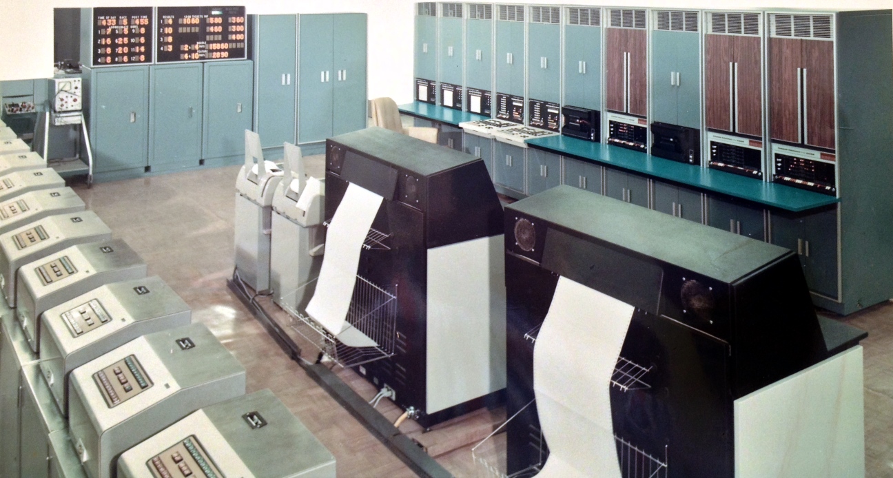
This image is of one of the PDP8 based totalisator computer rooms in the USA, probably the first, which was at Georgetown. The second page of the brochure above refers to the J11 push button issuer, under the heading TICKET ISSUING MACHINE. A row of 11 J11s is in view of the image, spanning the bottom left hand corner. No, "11 J11s" is not a typing mistake, they are J11 Ticket Issuing Machines and there are 11 of them visible in the image, although there are probably more out of view.
The PDP8 Computer and High Speed Reader and Punch, mentioned under the ELECTRONIC EQUIPMENT heading of the brochure, can be seen above the dark blue work shelf spanning the long row of equipment racks at the top right of the image. From the right hand end of these equipment racks, the first rack has a double set of two centre opening brown doors, below which is a PDP8 control console. Moving left, the same can be seen in the second rack which contains a second PDP8 computer. The following rack has a pair of blue doors below which is a paper-tape reader and punch. The fourth rack has a double set of brown doors again, containing a third PDP8 computer with its console visible. The following rack with blue doors again, has another reader and punch.
In the line of equipment in the middle of the room in the image, two of the line printers can be seen on the right hand side, which are black, as well as two Teletypes, which are grey and white, on the left hand side of the line printers. These are also mentioned in the brochure under the heading ELECTRONIC EQUIPMENT.
Finally, in the brochure under the heading DISPLAYS, it refers to light box indicators, Results and Dividends displays, Time of Day, Starting Time and forms of odds display. At the top of the image over the left hand side can be seen a couple of small light box displays. These are only for use by computer room operations staff, however similar displays will also be distributed around the racetrack for punters to see. The left hand box visible in the image shows Approximate Odds, Time of Day, the Race Number and the Post Time. The right hand display is results and dividends and shows results for 1st through to 4th as well as what looks like "$3.00 Tickets Pot", "Double Pots" and "Feature Pots" and an illuminated status of OFFICIAL in white at the top.