This is one of several pages relating to the history of the automatic totalizator, its invention in 1913, the inventor George Julius and the Australian company he founded in 1917 which became a monopoly (later part of an oligopoly) in this field. This page contains a technical description of the historical Julius tote at the Eagle Farm Racetrack Museum. This is a history only non commercial page. If you wish to start from the beginning then go to the index .
Copyright © 2007 Email - totehis@hotmail.com
| A description of the Julius Tote Mainframe in the Eagle Farm Racing Museum |
Introduction
In 2007 The Queensland Turf Club converted the old Julius Tote machine room into a museum, with the Julius Tote Mainframe equipment as the centrepiece. I was asked by the CEO of the QTC if I could write some descriptions of the equipment for display in the museum. As I have never worked on these systems, I wrote the following six A4 pages and some shorter notes, based on information I acquired from three main sources during the decades since I first became aware of the Julius totalisators. The first source was information in old company documents. The second source was what I had been told about these systems by people who had worked on them, managers and engineers in head office and staff that I inherited when I became chief engineer of the computer totalisator systems, which superseded the Julius Totalisators in the Brisbane region. The third source resulted from examination of the equipment to determine function. Actually the "J8 assembly drawings" section is a seventh page, however the one in the museum differs from the one presented here for the Internet.
As I have not seen a technical description of a complete Julius Tote, let alone a functional specification anywhere, I have presented these descriptions here. Some of the introductory information here is provided elsewhere on this site however I have left these pages as they appear on the actual equipment. The images on this page except for the J8 ticket do not appear on the original pages as they are attached to the actual equipment. Seeing this system demonstrates that mechanical computing on an industrial scale did exist.
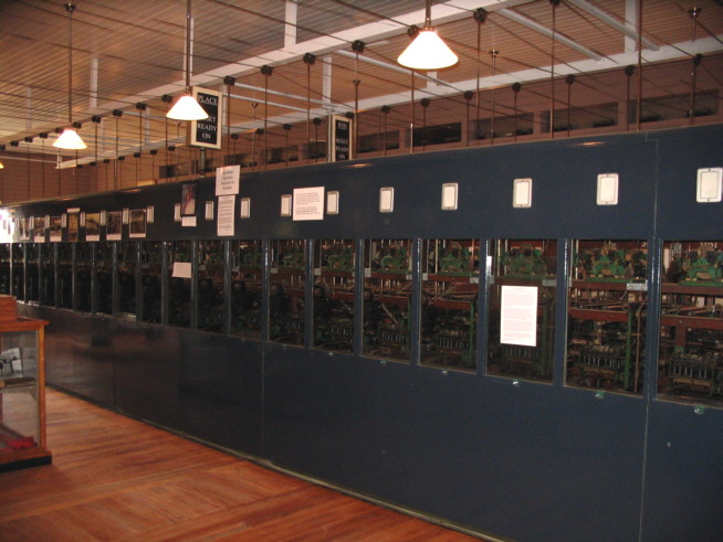
The Eagle Farm Racing Museum Julius Tote
Page 1 titled First and Last can be seen in the centre of the tote frame under the sign protruding above the top of the frame.
Page 2 titled An electromechanical shaft adder, can be seen on the third adder window in the frame from the right hand side.
The description of the public odds indicator drive can be seen in the tenth window from the right hand side.
The black RESET READY ON indicators above and to the sides of the middle of the frame are described in the "Place Pool Reset and Ready Switches" section below
Charles Barton, the last Chief Engineer of this system, whose picture I have placed on this frame, would have loved to see this!
Oldest Automatic Totalizator (Mainframe) in Australia
Page 1 First and Last
George Julius (later Sir George Julius) invented the world’s first automatic totalizator here in Australia in 1913. This original invention was installed in Ellerslie New Zealand. He founded the Australian company Automatic Totalisators in 1917 to develop and export these totalizators. This electromechanical Julius tote is a descendant of that original invention and was manufactured by Automatic Totalisators in the 1940s. By 1970 with few exceptions, every major racing centre in the world used totalizators manufactured by this Australian company, which were in service in 29 countries.
This is the machine room or in contemporary parlance the computer room. This is a large scale, multi user, real-time system. These systems existed long before the invention of the world’s first electronic computer. This one had 128 electromechanical Ticket Issuing Machines attached to it distributed in totes around the track.
A Julius tote was installed in Longchamps France in 1928 with 273 terminals and the one in White City London was upgraded to support 320 terminals. One of these systems was demonstrated in Sydney in 1920 capable of supporting 1000 terminals and a sell rate of 250,000 tickets per minute.
There is a school of thought that these early Australian totalizators were the first computers. The director of the London Science Museum wrote in his New Scientist article dated 29 October 1987 titled “A sure bet for understanding computers”; “The Julius tote with its automatic odds machine is the earliest on-line, real-time, data processing and computation system that the curators of the museum have identified so far”.
This frame houses a Win and Place totalizator. The front totalled the Win pool and the rear is duplicated for the Place pool. It supported a field of 24 runners. Inside the windows there are electromechanical shaft adders one for each runner plus one for the grand total. The adders have odds calculating devices attached to them which drive barometer indicators on the outside of the East and West walls of this building for public display. These indicators have two vertical channels for each runner one for the Win and one for the Place marked with imperial odds. Metal bands rise up from each runner’s odds calculator, win and place, through the roof of the frame and across the ceiling in both directions to the Eastern and Western indicators, then outside to move visible indicating strips in the channels mentioned above. A commission gearbox subtracted the commission from the pool for the displays.
This system was superseded in 1979 by a PDP11 based digital computer totalizator also manufactured by Automatic Totalisators. It was long thought that the last of these Julius electromechanical totalizators to cease operation was at Harringay London in 1987 until an email was received in 2005 from Caracas asking how to make adjustments to their Julius tote to bring it up to modern day standards. At the time of the email, that system had been in operation for 48 years. The lifespan of computing systems has certainly changed over the years!
These once common Australian totalizators have disappeared mainly under bulldozer tracks. We are fortunate that this example still remains, a reminder of an Australian achievement, courtesy of the Queensland Turf Club.
Webmaster's note: Having spent my working life in electronics/computer engineering, whenever I see the equipment in Julius Totalisator machine rooms, like that in the image above, the word Mainframe comes to mind. Were these the world's first mainframes?
Page 2 The electromechanical shaft adder
The shaft adders, one in each of these windows, totalled the investments on each of the runners and one at the end of each row kept a grand total of all investments on the associated pool.
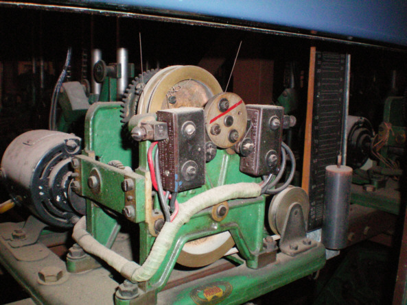
An electromechanical shaft adder
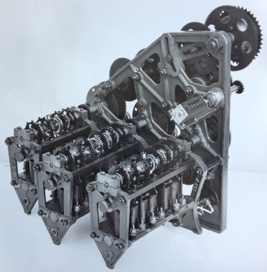
Note: This shaft adder is of a similar vintage to the ones used in the Eagle Farm system the main difference is that this is a 3 shaft adder and the ones on display in the museum are 2 shaft adders.
The heart of the shaft adder is the epicyclic gear train. These adders have two horizontal shafts with epicyclic gears visible near the top of the adder. The adders were powered by a horizontal drive shaft running the length of this frame driven by DC motors at the northern end. The adding shafts in the adders were driven by a spring for each shaft, which was wound up by the drive shaft. When the adding shaft spring was fully tensioned a clutch disengaged the shaft from the main drive. As energy was removed from the spring by escapement wheel movement resulting from bet traffic, the clutch engaged again to wind the adding shaft’s spring back up. The adding shafts have escapement wheels on them, 6 on the front shaft and 2 on the rear. These wheels moved one tooth at a time when the associated solenoids visible underneath the adding shafts were activated by a ticket-issuing machine recording a transaction. The number of teeth on the escapement wheel determines the value of the bet. The more teeth the lower the value. This system supported Ł5 Ł1 10s 5s bets which was translated to $10 $2 $1 and 50c when decimal currency was introduced.
Proponents of the electromechanical systems would boast that this system could do something that the next generation computer tote could not. It could record multiple bets simultaneously whilst the new computer tote which existed prior to the days of multiprocessing had to record bets sequentially albeit at a rate that made it all look instantaneous. In other words any combination or all of the solenoids on a shaft adder could be activated at the same time. The epicyclic gear train took the different value bets resulting from the different escapement wheels rotating and activated the display counter to keep a running total of investment. In the event of a drive failure to an adder, all adders were fitted with automatic cut outs, activated by a mercury switch, to prevent loss of bet registrations and raise alarms, illuminating one of the lights above the adder window for attention. Automatic Totalisators even manufactured its own plastic plugs and sockets visible on the right hand side at the bottom rear of each adder.
Julius Tote Odds Calculators
Behind each runner's adder is an odds calculating device. Each odds calculator consists of a vertical and horizontal slider that moves on a transport mechanism consisting of two rods each. At the end of each row were the grand total shaft adders with the associated commission gearbox and winding gear for raising the vertical lift sliders on every runner’s adder to represent the net pool grand total. The horizontal component for each runner was produced via the associated adder's odds chain sprocket wheel, at the very top of the adder, which let the associated horizontal slider out in accordance with the investment on that runner. Hypotenuse arms formed right triangles for each runner by connecting the vertical and horizontal sliders. The angle at the top between the vertical slider and the hypotenuse arm represents the odd for its associated runner. Mathematically the trigonometric ratio Cotangent of this angle is the odd for the associated runner. In other words, what is being measured is the gradient of the hypotenuse arm ΔY / ΔX or Rise/Run. On this angle between the vertical slider and the hypotenuse arm, or in other words the adjacent and hypotenuse sides of the right triangle, is a pulley arrangement. This drove some cams via a wire, operating some switches, to drive a small motor, which in turn powered the large barometer style odds displays mentioned on page 1. The hypotenuse arms mentioned above can be easily seen behind the adders or by looking down the length of the frame at either end. They can then be used to identify the vertical and horizontal sliders.
For remote locations such as the centre of the racetrack or a loft, odds transmissions were achieved by the use of a variable resistance, mounted at the important angle mentioned and utilising the Wheatstone bridge principles. The remote receiver sensed any out of balance transmitted by the adder unit and drove itself and the odds display until the bridge centre leg potential was once again null and therefore equalling the transmitted odds.
Page 3 The Distributor Cubicle
These racks house the Distributors (Scanners), the overlap relays and ancillary control equipment.
The distributors are at the top of racks 2, 3 and 4. They are a circular piece of equipment with four concentric rings. Two studded metal contact rings surround two continuous ring contacts with a rotating arm spanning the diameter of the outer set of studs. This arm rotated when the equipment was in operation and electrically connected one of the continuous rings with the inner circle of studs one at a time and the other continuous ring connected with the outer set of studs in sequence. One set of studs serviced the Win pool and the other the Place pool. The function this performed was to allow multiple Ticket Issuing Machines (TIMs) to be attached to a single escapement wheel solenoid in the adders. This was achieved by sequencing the supply voltage in the continuous rings to each stud and consequently the stud’s attached TIM, which provided a circuit to the attached solenoid, in the runner handle selected adder, if the pool selection knob on the TIM was pushed down indicating a sale. In contemporary terminology the scanner provides an enabling pulse, which will allow a transaction cycle if the TIM has a sale pending. The Win/Place knob on the TIM selected the appropriate inner or outer set of studs in the distributor. In the event that multiple TIMs attached to the same adder solenoid, in every runner’s adder, selected the same runner, meaning the multiple TIMs were now attempting to trip the same physical solenoid, the scanner serialised access to the associated solenoid, into the appropriate number of activations, so every bet was registered. There are 16 studs on each of these scanners allowing 16 TIMs to be attached to one shaft adder solenoid. Each of the 8 scanners is associated with one of the 8 solenoids in all the shaft adders, the actual adder being selected by the TIM’s runner handle. This provided a capacity for this system of 16 X 8 giving 128 TIMs. Optimum scanner rotation was between 90 to 120 RPM.
Distributor Panels with museum adornments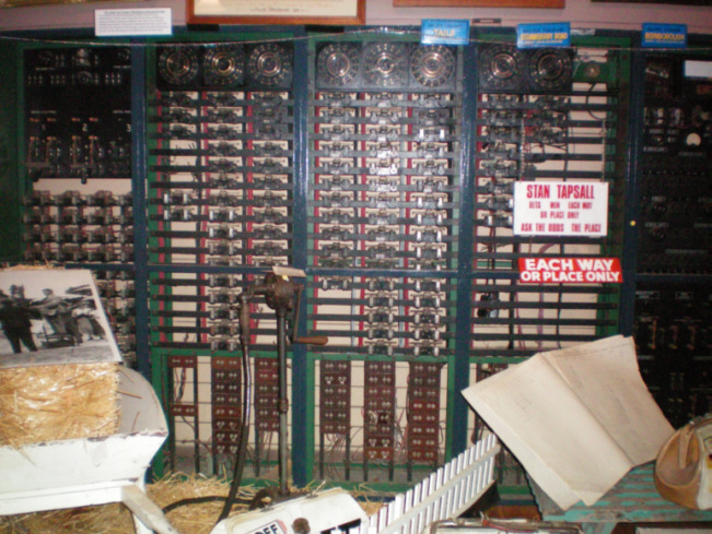
Note: The scanner racks are not in their original location. They were located to the right of their current position and stood away from the wall creating a cubicle behind them for access to the rear of this equipment and the drive motors for it.
There are overlap relays beneath the scanners connected to the scanner studs. Once a sell transaction was initiated by the TIM and when the distributor selected that TIM, a set of contacts in the overlap relay connected the supply voltage to the transaction circuit and its own coil, keeping itself activated, which held the supply voltage, after the distributor arm had passed its stud, to the TIM and associated adder solenoid, until the machine cycle completed. Beneath the overlap relays are switch banks, which could isolate a TIM in the event that it had a fault and did not release the transaction circuit.
These old systems have analogies to modern computing systems and these scanners are a good example of this. They are Time Division Multiplexers that existed long before the electronic signalling methods that made this concept commonplace.The functionality of these devices was replaced in their successor by a polled protocol operating on tri-state lines, which curiously also supported 16 TIMs per line.
It is interesting to note that the Sales Bell relay in the right hand rack at the top, along with two other relays are implemented using Mercury switches. This bell marked the start and stop of betting. Mercury is a metallic element and consequently a good conductor. It is a liquid at room temperature. An arced tube of glass contains mercury and a central electrical contact and a contact at each end of the tube. If the tube is oriented past the horizontal in either direction the mercury pours to the low side and makes a circuit between the low-end contact and the centre contact. A restriction in the flow implemented a delay ensuring the bell always rang for the same length of time.
Webmaster's note: This Julius Tote Mainframe had a Front End System based on the Distributor/Scanners shown in the image above.
Page 4 The Ticket Issuing Machine J8
This was the working end of the system, also manufactured by the Australian company Automatic Totalisators.
This system had 128 of these Ticket Issuing Machines (TIMs) distributed in totes around this track as follows. Main house 48 Ledger Stand 6 Sub House12 Jackpot tote 8 Members 28 Lady Members 10 Front Public Stand 6 Top Public Stand 10. The Main house mentioned above is the downstairs of this building.
Note: The reference above to the downstairs of this building refers to the ground floor lever underneath the ex Julius Tote machine room which is now the museum.
It was at these windows where these TIMs were installed that the punters queued up to place their bets. The word queued, used above, is used rather liberally, photographs of Brisbane racetrack tote outlets in the era that these totes were in operation often had a standing room only crowd swamping the totes. There is half a century of totalizator history based on machines like this one before the inception of the TABs, which diminished the racetrack attendance in conjunction with the introduction of other forms of gambling.
A J8 Ticket Issuing Machine
The handle rotates in an arc and is positioned at the required runner number. The knob on the top of this handle moves backwards and forwards along the longitudinal axis of the handle. The forward position selected the Win pool and the backward position selected the Place pool. When the same knob is pushed down the transaction was recorded and a ticket printed which was ejected from the machine at the slot in the top. A J8 ticket is shown below.
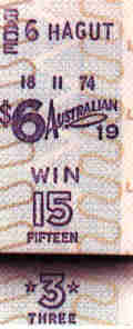
A ticket printed on a J8 ( Animation above )
The value of the bet was fixed in this system, determined by which escapement wheel solenoid the TIM was attached to. Later Julius totes supported selectable value at the TIM.
The HAGUT printed on the ticket shown, is a security code, which was different for every race and was automatically selected at race increment. Barrels with the code type were installed in the machines for the meeting. The L down the right hand side of the ticket is an added security feature and was different for each race as was the ticket colour. For this reason the printer paper in every TIM had to be changed every race. The code words and ticket paper security letters were kept secret until the race day manager instructed the tote house managers to open the race day code security envelope.
A trip relay in the TIM terminated the transaction cycle. Its coil and the transaction circuit are in series with a normally closed set of its own contacts so when these contacts open they cut the supply to its coil, resetting itself and the overlap relay heralding the end of the transaction cycle. The trip relay is adjusted to trip after the adder solenoid has tripped by adjusting the tension on the trip relay swing arm.
Page 5 The Ticket Issuing Machine J8 Part 2
The Win and Place counters visible at the bottom right corner of the TIM were recorded each race for every TIM. The Win and Place race investments for every TIM were then manually added to produce a grand total investment on the Win and Place pools and this was compared with the GT adder registrations providing a means of error detection.
Internally, the runner handle moved two contacts over two sets of studs arranged in the same arc with 24 studs in each set. Each outer arc stud is connected to the associated Win adder solenoid for this TIM bank, in the runner’s shaft adder with a number matching the number of the stud. Hence stud one attaches to runner one’s Win shaft adder and stud two attaches to runner two’s Win shaft adder etc. There is the same arrangement for the inner arc studs and the associated Place adders. If runner 15 was selected with the handle, the knob pushed forward for the Win pool and the knob pushed down to indicate a sale, the Win contact attached to the knob, contacted stud 15 on the Win arc completing a circuit enabling the scanner pulse to travel to the solenoid associated with this TIM bank in shaft adder 15. There is a lot more to this transaction circuit however that is well beyond the scope of this introduction.
Postscript:
This has nothing to do with the documentation on display in the Eagle Farm Racing Museum. Many years after this museum documentation was written, Neville Mitchell an ex ATL (Automatic Totalisators Limited) engineer and manager wrote an email, which contained information about this transaction circuit. Following is the relevant extract from his email:
In the Julius electro mechanical totalisator there was always three solenoids or trip relay device. The series circuit created by the scanner, to the ticket machine's demand for a bet, included firstly the OVERLAP Relay (OLR) in the distributor, then the TRIP COIL solenoid in the Ticket Machine, finally the (GT) trip solenoid in the Grand Total Adder. As the current in the series circuit rose to one amp, the solenoids release almost simultaneously, thus completing and recording the bet.
The setting of the one amp trip current, was tuned accurately by use of the ATL "Love Box" test set, comprising a ammeter and a cranking handle, so the optimum setting could be tested at speed.
The later mini totes, such as the COUNTER Totes, had specially designed SEDCO rotary digital counters, with a solenoid wound to act similarly to the OLR and GT solenoids. All the counters in a Counter tote were identical.
The switch on the top of the TIM was used to turn it on and off. The last position on the runner handle arc was used to print a test ticket.
When a transaction was registered on the TIM by pushing the Win/Place selector knob down the runner selection handle and this knob were locked in place until the transaction cycle was complete. If there was a fault and the transaction cycle did not terminate correctly the handle release button on the top of the TIM was used to release this lock, after the problem had been investigated, so that the TIM could continue operation.
These machines had to be moved between the Eagle Farm and Doomben gallops, Albion Park trots, Gabba greyhounds and Ipswich gallops as there were insufficient machines to populate all the tracks. Today’s TIMs are still moved for the same reason. Sometimes during the Winter Carnival we feel exhausted moving the large number of PC based modular TIMs; after having to use a hydraulic wheelbarrow to move the J8 recently I will only consider ourselves fortunate in future.
Note: As you cannot see the actual J8 TIM in the museum, I will add that these electromechanical TIMs were significantly heavier than the PC based TIMs and earlier microprocessor based electronic TIMs of my era.
I lament that Charlie Barton, Chief Engineer of this and other Julius totalizator systems in Brisbane is no longer with us to see this system preserved. It was his dream to preserve and possibly restore one to an operational condition for public display. Alas, it was my fate to be Chief Engineer of the first on course digital computer based totalizator systems for the Brisbane metropolitan clubs, which brought an end to the operation of these magnificent machines. I find it ironic that someone who never worked on these electromechanical totalizators nor indeed saw one working is left to write about it. This would have been very different just 10 years ago. It is now 2007, 29 years since this system last operated.
Acknowledgement: Thanks to Ron Findlay for assisting me with questions I had regarding the J8. Ron used to work on the J8s and continues to work on the current generation of TIMs.
Page 6 The Tote Control Console + The Human factor
The Tote Control Console was used to set and display variables such as race number, field size, scratchings and the number of place dividends. It also provides operational coordination between the machine room staff and the operations control staff.
A Julius Tote Control Console
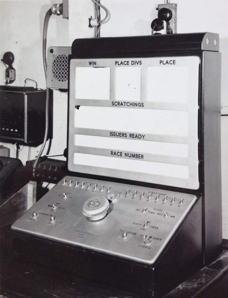
The console above is at Harold Park in 1958 however it is the same as the one at Eagle Farm.
When the large knob in the middle of the Tote Control Console control panel was rotated clockwise the race number was incremented. This caused a barrel with the race number type to be rotated to the next number in every TIM. All the TIMs clanked in unison as this selection was made. The scratching switches introduced an open circuit in the escapement coil circuits in the adder corresponding to the scratched runner.
There is an emblem on the large knob mentioned above with Premier on it. This was the product name that George Julius gave to his totalisator. This emblem is also visible on the J8 TIM. Automatic Totalisators is visible engraved below the Knob.
To give some idea what it was like in this room when the system operated the following paragraph is an extract from a company magazine called Tote Topics. This article was written in 1968 and compares electromechanical totes with the then new computer based ones.
In the machine room of an electromechanical totalisator there is motion, constant motion, and noise. With betting in progress, the constant chatter of the escapements blends with the purring of the counters and the low rumble of the drives to give a quite characteristic sound. This sound, both in intensity and pitch, indicates to the experienced totalisator operator, even more clearly than his eyes, the state of the queues outside and the conditions around the selling houses. He scarcely needs a clock, so accurately is he able to predict from the betting pattern the time to the start of the next race. The equipment consists of row upon row of shafts and gears and escapement wheels and mechanical counters. At first sight it seems entirely mechanical as the electrical portions are buried deep inside.
It is interesting to contemplate the human side of this system. The following is a transcription from an audiotape recorded by Neville Mitchell, a long serving Automatic Totalisators Manager and excellent source of information about these systems.
The mystique of the machines was something I experienced, particularly in Melbourne, not so much in Sydney. The men who operated the four major tracks there had been with these machines since 1936 and on the decommissioning day, I saw emotions that were quite unbelievable. They were seeing the last day of operations with this sort of gear. The strictness with which the engineers ran these systems was somewhat akin to a military operation; they really had a lot of power. They had a lot of routines set down and to be an apprentice in those days was a lot of sweeping the floors and making the tea for a long long time before you actually got your hands on any piece of equipment. And I believe in the early days in Melbourne, if an apprentice was seen with his hands out of his pockets in the machine room, he would get a swift slap around the ears. The same thing applied in New Zealand. I read some stories from there and I actually knew a couple of the engineers and they applied the same very very strict mode of operation on their set-ups. They were extremely proud of these machines and some of them spent all of their, what you would call, idle time in routine maintenance and polishing of brass and things like that, that made these machines absolute showrooms.
Page 7 J8 assembly drawings
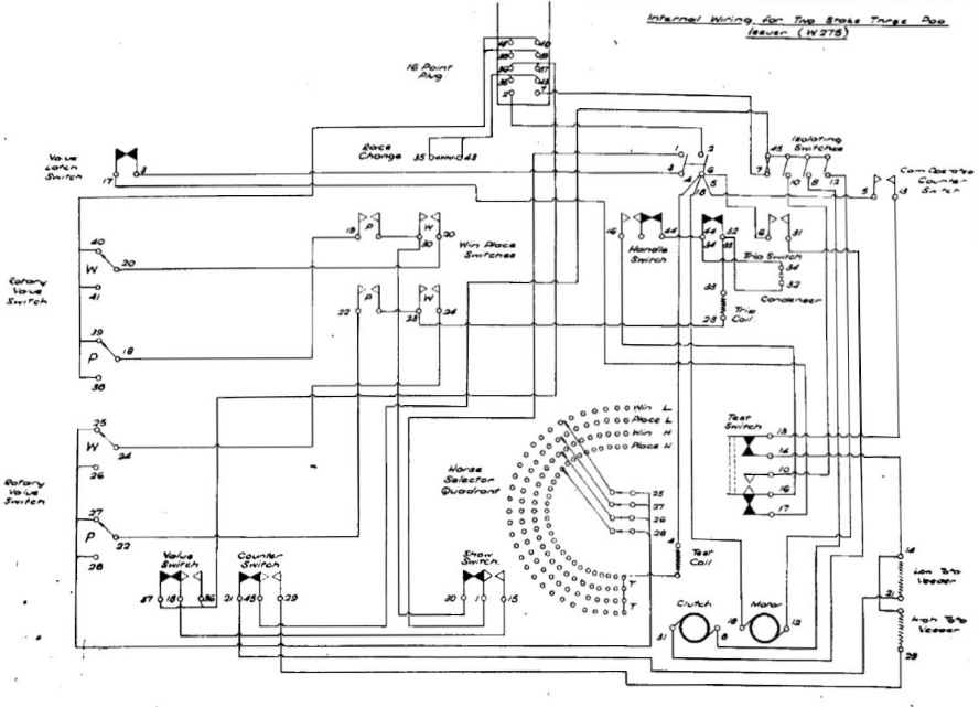
This set of drawings is an extract of some pages from a document detailing the assembly, wiring and test procedure for J8 Tims for Randall Park in Ohio. Essentially these are the same machines used on this totalisator except that they supported an additional pool called Show. As this historical documentation is now very scarce this is the closest fit that could be found and gives an insight into what was involved in manufacturing this type of equipment.
You will notice GAJ part numbers on these drawings. These are George Alfred Julius’ initials. Additionally the draughtsman’s name is Noble. This is Norm Noble, a long serving Automatic Totalisators employee. I remember him well. As the company supported operations, engineers in the field would often require urgent shipment of replacement parts out of the normal working hours of the Head Office and Factory. Long before the days of mobile phones there were times when it was not possible to contact the people responsible for providing support. As these parts requirements were usually urgent it is fortunate that there always seemed to be people willing to go the extra mile and help out in areas for which they were not responsible as they realized that operations was the coal face of the company and was the place our products were judged. Norm was one of these people. I could always rely on him to go to work in Sydney on weekends, public holidays, or otherwise out of hours to send me anything I needed. There is a photo of the ATL drawing office in the "Memories of the Factory" chapter that pre-dates my time which has Norm Noble in it, unfortunately he is facing away from the camera.
These drawings were made at a time long pre-dating computer drawing, CAD and CAM applications. I recall draftsmen in the 1960s in their drawing offices standing, or sitting on bar stools, in rows, at their large drawing stations with their angled drawing surfaces and spring loaded large setsquares that could sweep across the whole drawing area. Earlier photographs indicate that the drawing office draftsmen who made these older drawings sat at normal office desks. It is interesting to note, that documentation for these old systems, seems to always have been released to a particular person. The document from which these drawings are extracted has a title page indicating that it was released to S.Huss in the Assembly section on 12/9/1950. I have seen other manuals in the form of bound books with the name of the employee to whom it was released embossed on the cover.
Following is a transcription of a page from this document for clarity and to save download time. This and the images that follow, as with the Julius tote in the museum, are examples of mechanical computing on an industrial scale.
General Assembly of Randall Park issuer
Sequence of Operations & Parts Fitted
| 1 Type Wheel Peg & Frame | 23 Other Side of Issuer Wiring Former |
| 2 Type Wheel & Win, Place, Show Arm Assembly | 24 Selector Quadrant & Wiring |
| 3 Locking Rod Assembly & Ribbon Bracket | 25 Win, Place, Show Arm, Anchor & Spring. Show Switch Bumper Assembly. Pool Selection & Bracket. |
| 4 Intermediate Gear Bracket & Gear | 26 Condenser & Clips |
| 5 Handle Assembly. Handle Stop & Brush Holder | 27 Motor & Brushes, Chain & Split Link. |
| 6 Taper Pinning Operation | 28 Ribbon Feeding Operation |
| 7 Platen Assembly | 29 Issuer Box & Hinge &Wiring Clips |
| 8 Win Place, Switch Assembly & Slide Rod | 30 Plastic Issuer Handle , Pin & Circlip |
| 9 Paper Feeding Assembly | 31 Electrical Setting Details |
| 10 Trip Coil Assembly | 32 First Test |
| 11 Ribbon Rewind | 33 Taper Pinning Operation |
| 12 Quadrant Supports, Issuer lifting Handle & Posts & Cover posts | 33A Ticket Issuer Chute |
| 13 Handle Release, Double Pole Switch & posts, Test Switch, Handle Release Lever & Spring | 34 Covers & Horse Number Segments. |
| 14 Test Coils, Wiring Brackets & Cover Catches | 35 Final Test |
| 15 Latch switch & Show switch | 36 Spray Finish issuer Box. |
| 16 Cam operated Counter switch | 37 Attach Nameplate |
| 17 Guillotine Lever, Anchor & Spring Printing Lever, Anchor & Spring | 38 Clean & Inspect Box |
| 18 Value Slide Lever & Spring |
| 19 Rotary Switch, Retaining Posts & Value Leaf Switch Assembly |
| 20 Value Release & Spring |
| 21 Veeder Assembly |
| 22 Issuer Wiring Former & Brushes |
 Go back to the index
Go to the bottom of the page
Go back to the index
Go to the bottom of the page
Following are image extracts from the document.
This appendage to the Randall Park project J8 drawings above, has nothing to do with the museum. I have added it just for interest regarding the Randall Park project. An ex Automatic Totalisators Limited engineer Rod Richards worked on this project. He made the following comment about the Randall Park project relating to his working on it in the Meadowbank factory:
This must have been 1950 as we worked on the Randall Park job in the factory as a matter of urgency, during the Xmas/New year period, to have the machine finished in time for the Randall Park Carnival racing period. From memory we worked a lot of overtime to get the job finished and I believe air freight was involved. I think Alan Lakeman and Jim Macintyre were just two of the Meadowbank engineers that worked on the installation at Randall Park.
Additionally Rod has a connection with the Brisbane region Julius totes. There were five Julius Totes in the Brisbane region when I started working for the company, which were at Albion Park Trots, Bundamba Gallops, Eagle Farm Gallops, Doomben Gallops and the Gabba Greyhounds. Rod installed the Julius Tote at Bundamba Gallops in 1950. I moved to Brisbane in 1978 with the computer based totalisator systems that replaced the Julius Totes at all five tracks including Rod's Julius Tote at Bundamba. Rod worked at Automatic Totalisators Limited in a different era to Neville Mitchell and I. Neville and Nancy Mitchell and Narelle and I met with Rod and Elizabeth Richards for the first time in a coffee shop in Parramatta in 2015, 65 years after Rod's working on the Randall Park project and installation of the Bundamba Julius Tote. we all had a wonderful time together reminiscing about Automatic Totalisators Limited.
Coincidentally, Rod Richards met Rex Turner at a Bowling Club which they were both members of. Rex was the installation engineer for the computer systems that replaced the Julius Totes at the five racetracks in the Brisbane region. They, without anyone informing them, discovered they had both worked for Automatic Totalisators Limited. I later informed them both of the irony that Rod had installed the 1950 Julius Tote and Rex had installed the computer replacement for Rod's system in 1978/79.
There is a detailed description of the General Assembly of Randall Park issuer document above in the second page of the Photo Gallery of this website. To view this, scroll to the bottom of this page and select the Go to the index option in the navigation bar. Then in the Finally section of the index, click on the Photo Gallery continued chapter. Now scroll down in the Photo Gallery index to the heading Ticket Issuing Machines (TIMs) and select the thumbnail of a J8 with the associated text starting with the text The J8. This TIM could be called iconic or famous.
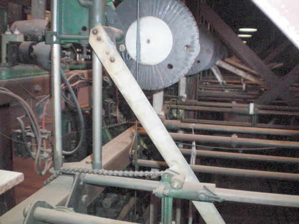
Description of one of the public odds indicator drives
Remember the following text is attached to the base of one of the indicator drive units in the museum. It can be seen as the short strip of paper in the upper half of the tenth window from the right hand side, in the mainframe in the image at the top of this page. One of these indicator drives is shown in the photo below. As the note is below the odds indicator drive in the museum the following text refers to the device being above whilst the image of it in this page is below. The odds indicator drives are located above their associated adders.
The device above this note is the barometer indicator drive for the runner associated with the adder below. The odds calculating mechanism has been described in the adder description attached to one of the windows in this row and the Place Commission Gearbox description at the right hand end of this frame. Behind this unit, the angle between the hypotenuse arm and the vertical is sensed by a pulley located on a projection of the hypotenuse arm past the pivot point. A light cable anchored to the frame behind the adder runs up from the anchor, through a guide pulley located on the vertical slider, around the sensing pulley back to a third pulley on the vertical slider above the first and then up near the roof of the frame. The action of the sensing pulley is to either release or pull the cable depending on the odds changes. The cable is then directed from its roof location to above the upper pulley in this device it descends under this pulley, up again over another pulley and ends dangling with a weight attached next to the odds scale on the right hand side of this note.
One of the Barometer Indicator Drive Units in the Eagle Farm Racing Museum
The scale and weight provide a local indication of the odds. The more the sensing pulley pulls the cable the more it lifts this weight and vice versa. There is a corresponding rotation of the pulley at the top of this device. This light cable mechanism is only capable of rotating this low resistance pulley. It is not capable of moving the heavy indicator band and weight, in the associated runner channel of the indicator on the outside wall, the distance required. This rotary motion of the top pulley on this device turns the cam wheel with the red line across it. When the odds on the outside indicator match the odds displayed by the cable weight here the line is horizontal. As the odds calculating mechanism changes the odds the micro-switches attached each side of the cam wheel are activated by cam movement sensing the required direction and amount of movement required causing the motor to drive accordingly. The motor which is capable of driving the external indicator ribbons and weights, drives a second pulley in this device, an arc of which is visible near the base. This pulley has two metal bands attached to it that run through the roof of this frame then split across the ceiling in both directions to other pulleys on top of the east and west walls. These pulleys in turn move wider, coloured metal bands with weights at the end which are moved up and down the respective runner channels. The coloured part of the band visible from the outside of the building, gives a barometer style indication of the odds. You may have noticed the circular variable resistances located near the top of the hypotenuse arms. These were used to drive an infield indicator.
These are notes not included in the text displayed in the museum, to provide additional information relating to the image above:
The two aluminium vertical bars visible behind the indicator drive unit are the transport mechanism for the vertical slider described in page 2 above. The small black pulley visible between the vertical slider transport bars is the third pulley attached to the vertical slider as described above the image. The pulley, half of which is visible below and behind the third pulley is the angle sensing pulley attached to the extension of the hypotenuse arm also mentioned above the image. This pulley is located immediately left of the left hand vertical slider transport bar where the silver bar meets the top of the green vertical slider.
For the particularly astute, the cable that should be running around these pulleys has been pulled out of the third pulley and should not be running directly to the ceiling from the sensing pulley on the extension of the hypotenuse arm. This is nigh impossible to see in this small image but is probably why the weight on this unit is dangling below the bottom of the scale.
Note the once famous PREMIER Automatic Totalisators Limited emblem at the bottom middle of the image on the bottom of the indicator drive unit base.
A note next to the Place Pool Reset and Ready Switches
The Reset and Ready switches for the Place Pool, where this note is attached are on the Julius Tote mainframe out of sight, off the far right hand side of the image below titled "The Eagle Farm Racing Museum Julius Tote", near the top of the frame. The Reset and Ready switches for the Win Pool, also out of sight of the same image below are around the top left hand corner of the end of the frame. Del's mention of the "remote control console" refers to the "Tote Control Console" described in page 6 above.
Whilst researching the workings and operation of this machine, Del Linkhorn a long serving ATL Manager in New Zealand and later South Africa wrote the following paragraphs in answer to my questions. It relates to the switches next to this page, the indicators on top of this frame and embedded in both ends and the Win and Place Max/Min, the Place Two/Three, the Win Units On/Off and the Place Units On/Off switches and status displays on the Tote Control Console on display in this room. The gearbox settings mentioned refer to the Win and Place Commission Gearboxes visible inside the windows at each end of this frame. The Win Pool Reset and Ready Switches are on the diagonally opposite corner of this frame.
The indicator panels located on the centre of each side of the Win/Place machine frame were to indicate the status of each betting pool. The "Win" or "Place", "Reset", "Ready" and "On" lamps were operated from control switches located on each end of the machine frame and on the remote control console unit. When the engineers had reset the adder counters to zero for each race they would turn on the "Reset" switches. The senior engineer would then check the counters, gearboxes, indicators, etc to ensure that the machine was ready to open and, if satisfied, would turn on the "Ready" switches. The person allocated the responsibility to set the field, scratchings, gearbox settings, etc on the remote control console unit for each race, (sometimes the Tote Manager or the Secretary), after checking all status lamps were indicating the correct settings, would then open the betting by turning on the Win and the Place pool switches. The machine room staff would then know that the betting was "On" from the machine frame centre panels.
The two indicator lamp units, located on each side of and at the end of the machine frame, were to indicate the settings of the automatic display gearbox settings. On the Win gearbox end, "Minimum" or "Maximum" and on the Place end, "Minimum" or "Maximum" and "Two Dividends" or "Three Dividends". Some frames also indicated "Win" or "Place", "Reset", "Ready" and "On" as a second status display on each end of the machine frame. On some systems they had a "Mean" gearbox setting in addition to the normal "Maximum" and “Minimum" ratios.
The following are some notes on Del's last paragraph which relate to the image below that do not appear in the Museum.
In the paragraph above, Del refers to "on the Place end, 'Minimum' or 'Maximum' and 'Two Dividends' or 'Three Dividends' ". The "Place end" of the frame is visible in the image below.
The "Minimum" or "Maximum" indicators that Del mentions are the four black indicators visible on the top right of the frame indicating PLA MAX and PLA MAX on top and PLA MIN and PLA MIN on the bottom. The way these indicators work is that the left hand indicator shows what is being commanded from the Tote Control Console and the right hand indicator shows what the equipment has been set up for. Before the machine is set in operation, the left and right indicators should illuminate the same option. In other words PLA MAX PLA MIN or vice versa would be a no-go indication requiring correction to the set-up of the machine.
My understanding of the minimum and maximum gearbox settings mentioned by Del, is that they were selected based on the expected attendance and consequently bet traffic, which ensured the odds calculating units did not end up operating at either extremity of the horizontal of vertical sliders where they became less accurate.
The "Two Dividends" or "Three Dividends" that Del mentions are the four black indicators visible on the top left of the frame indicating 2 DIV 2 DIV on top and 3 DIV 3 DIV on the bottom which have to match as mentioned above.
Regarding the commanded settings for PLA MAX or PLA MIN and 2 DIV or 3 DIV indicators in the mainframe, from the Tote Control Console, there are switches for selecting these options that can be seen in the image below titled "A Julius Tote Control Console." On the right hand side of the switch panel in this image, underneath the long straight line of scratching switches at the top, there is a group of five switches, consisting of two switches with one below and two more below that. The top two switches have the word PLACE that applies to both switches and the two positions for the left hand switch is labelled TWO in the left position and THREE in the right position. This switch controls which of the left hand side 2 DIV or 3 DIV indicators will be illuminated on the top left of the frame in the image below. The two positions for the right hand switch are labelled MAX on the left and MIN on the right. This switch controls which of the left hand side PLA MAX or PLA MIN indicators will be illuminated on the top right of the frame in the image below.
The right hand lights in the PLA MAX or PLA MIN and 2 DIV or 3 DIV indicators in the mainframe are controlled by switches inside the mainframe which are close to the gears that need to be changed to comply with the requirement.
The Eagle Farm Racing Museum end view of the Julius Tote

The Place Commission Gearbox description following can be seen in the museum in the window in the door of the frame in the image above and is itself visible in the image above.
The page titled "Page 7 The J8 assembly drawings" presented above, can be seen above the window in the frame, in the image above.
The J8 assembly drawing images presented above can be seen below the black indicators, which are top left and top right on the frame in the image above.
A note attached to the Place Commission Gearbox
This was driven by the Place grand total adder and the Place main drive shaft and drove the Place pool grand total shaft high up on the left hand side. This shaft transmitted the Place pool total minus the commission to each runner’s Place odds calculating mechanism. The silver-gray hypotenuse arms, seen projecting near each runner’s adder into the space between the 2 rows of adders ahead, at different angles, are each positioned by a vertical slider controlled by the grand total shaft and a horizontal slider driven by each runner’s adder. The resulting angles between the vertical and the hypotenuse arms represent the odds for their respective runners and this is sensed and transmitted to the indicators. The Win Pool Commission Gearbox is at the far end. Below this gearbox are the Place and Win rheostats used to start and control the speed of the Place and Win main drive shafts. Below these and to the sides are the Place and Win main drive shaft motors. These are 120V DC.
Another note that appears beneath one of the framed white panels
These framed white panels can be seen above each adder window on the side of the mainframe, except the Grand Total adder, in the Julius tote shown in the image below.
The panel above this description and above each adder in this frame contains two status indicators. The top indicator is an alarm which illuminated if the associated adder lost drive power. The mercury switch at the bottom right hand corner of the associated adder raised the alarm when it detected that either of the adding shaft springs in the adder was unwound indicating that it was no longer being wound up by the main drive shaft. The bottom indicator shows the runner number if the associated runner is not a scratching. These lights are illuminated if the runner is not selected as a scratching on the Tote Control Console scratching switches. There is a tote control console on display in this room
Additional Information
New information on these Reset and Ready switches, as well as other aspects of control and communication between the machine room and the tote control room, has been received since this museum documentation was produced. As it differs a little and provides additional information I have provided it here as the images here best illustrate the quoted company document. None of the information presented below appears in the Eagle Farm Racing Museum.
I have provided copies of the following two images, which have already been presented on this page, to simplify cross referencing the text with the images eliminating the need for lengthy scrolling up and down to tie the explanation to the image. Remember that in the image immediately below, all the equipment seen in the front of the Julius Tote mainframe, which is for the Place Pool, is replicated at the back for the Win Pool:
The Eagle Farm Racing Museum Julius Tote
In 2007, I visited Riccarton Racecourse whilst in Christchurch and was very surprised to find a Julius Tote Barometer Indicator in excellent condition on the side of a building on the racecourse. I was further amazed to find that the Julius Tote mainframe that drove this indicator was still present in the building. I informed Professor Bob Doran from Auckland University of this and he organised a visit to see this system and identify what was still present and examine research and document it. As a result of this, Bob sent me many photographs of the equipment and some of the documents he found there. I never cease to be amazed how Bob, so entrenched in the future, having been Principal Computer Architect at Amdahl Corporation, designing tomorrow's computer systems and later a Professor working on educating the next generation of computer engineers could be so passionate about the past and the path taken to arrive at the present state of computer technology. One of the documents he sent me is titled Automatic Totalisators Limited Description of Electrical Circuit Diagrams. In this there is a page titled LIST OF CIRCUIT DIAGRAMS DATED 15/5/1935. One entry reads 3488 - 'Reset'; 'Ready' and 'On' Signal Lamp Circuits, which is dated 10/5/1935 and is included below.
Comments are required however, to relate this extract to the images, as there were several permutations of Julius Totes in the near half a century that they were manufactured. These differences arose because they were subject to continual development and had different capacity requirements. I have left the extracts from this company document unaltered to keep it original, however that leaves a discrepancy between the description and the machinery in the Eagle Farm Racing Museum, which leads to the need of the explanation that follows this extract.
'RESET', 'READY' and 'ON' SIGNAL LAMP CIRCUITS / Drawing NO. 3488.
On the Control Room Switchboard there are two sets of three signal lamps marked 'Reset', 'Ready' and 'On', one set being for Win and the other for Place. There are six corresponding lamps on the Machine Room Signal Board connected in series with the above lamps.
When a race commences the machine is closed by the Steward, as described elsewhere. The Manager then turns his Win and Place control switches to the "off" position and the Head Mechanic also turns the Control Switches on the Main Switchboard to "off" position. In this position none of the signal lamps are alight.
When the manager has been notified by the dividend calculators that they have obtained the figures from the Adding Units, he turns his control switches to the 'Reset' position which lights the 'Reset' lamp on the Control Room Switchboard and the Machine Room Signal Board, thus notifying the mechanics that the machine may be reset for the next race.
On each Odds Unit there is a reset switch which is only closed when the horse slider is pulled right back to the reset position. All these reset switches are connected in series with the two 'Ready' lamps and in series with the Control Switches on the Main Switchboard. When the head mechanic is satisfied that the machine has been properly reset and is ready for the next race, he turns his control switches to the 'On' position and the 'Ready' lamps then light up provided that all horse slides have been set to zero. This notifies the Manager that the machine is ready for betting on the next race.
When the Manager is ready to open betting on the next race, he turns his control switches to the 'On' position and this, as described elsewhere, completes the circuit for the coils of the Win and Place contactors on the Main Switchboard. These...
Oh Dear! That is where this PDF file ends on the word These! I presume the remainder was either not worth photographing or it was missing. I will add to it the only comment that comes to mind, that it will presumably end with and lights the 'On' lamp.
The Control Room Switchboard mentioned above was often a fixed installation switchboard near the operations centre, which was usually located at the place of highest betting activity aside from what is called the Machine Room in the document, which in my time was the computer room as I only ever worked on computer based totalisators. A mobile version of the Control Room Switchboard was developed, presumably to reduce cost and allow for the possibility of moving the control centre in small to medium sized installations. This mobile version was called an RDC or Race Day Control console and one is shown in the image below. The photograph of the RDC shown in the image below was taken in 1958 at Harold Park in Sydney and I have presented it here as the photograph and the RDC are both in good condition. Tote Control Console (TCC) is another name commonly associated with these devices. So where the Control Room Switchboard is mentioned, translate this into RDC. The Control Room in the extract above is where the Manager is located and the Machine Room is where the mechanics are located.
The Reset', 'Ready' and 'On' lamps mentioned in the document extract, relate to the RDC in this case, one set for Win and the other for Place. When the RDC is in operation the white areas on the vertical face of the RDC will have words appear on them, as there are lamp boxes behind these white facades and when a lamp is lit, the associated words corresponding to thinner layers of paint, create words. So inside the panels marked WIN and PLACE at the top of the RDC below, are the words RESET, READY and ON in the top row, followed by a row with MAX MAX and a final row with MIN MIN. These are individual status lights that will illuminate when their corresponding lamp is on, indicating the particular status is active. The MAX MAX and MIN MIN status lights are part of the Capacity Signal Circuit explained below.
The extract next mentions the six corresponding lamps on the Machine Room Signal Board. This Machine Room Signal Board, is implemented as two displays of three status lights each shown in the image above. Behind the middle light hanging from the ceiling, there is a tall rectangular frame, held up above the top of the frame by what looks like a piece of metal pipe. This display contains the permanently displayed word PLACE at the top indicating the three status lights below relate to the Place Pool processing equipment on the near side of the frame. Below the word PLACE are the status lights RESET, READY and ON arranged vertically.
A bit of explanation is required relating to the facade on this display on top of the frame in the image above. In its original condition this indicator had a glass front that looked completely white like the RDC panels in the image below. Similar to the RDC panels there were three lamp-boxes inside the indicator each with a separate bulb, to illuminate the words RESET, READY and ON when their respective statuses were active. As this glass was missing when I was providing the information for this display, I made a cardboard replacement of what this display used to show. I kept the writing white to give the idea of light shining through and made the backing black for contrast. Originally, all the displays on the mainframe had glass panels but they must have had some value as they seem to have disappeared over the years since this system ceased operations in 1979. This RESET, READY and ON display was the same on both sides when it was in operation, so you could read this information no matter which side of the sign you were standing. Instead of putting another cardboard representation of the display on the opposite side to the image above, I left the back open so visitors can see that it is a stack of lamp boxes.
The Reset status light illuminates when the associated Reset switch is turned on in the Control Room and the Ready status light illuminates when the associated Ready switch is turned on which is located on the frame in the machine room shown above, and the On status light illuminates when the On switch is set in the control room. Looking to the right of the indicator being discussed in the image above, there is an identical indicator above the opposite side of this frame where the Win Pool machinery is located. This second display provides the same information except it applies to the Win pool.
Looking at the image below, at the bottom of the inclined control panel, in the fourth row of switches/buttons, there are two buttons on the left hand side labelled WARNING BELLS , the left button of the warning bell pair is labelled PUBLIC and the right PAY. On the right hand side of the control panel there is another button labelled TEST ISSUER that causes the ticket issuing machines to all print a test ticket and to the right of this is the CHANGE RACE NUMBER key. This locks the large circular knob in the centre of the control panel, which is used to select the current race number. As changing the race number is a critical event, it has a key so the race number cannot be changed without authority and conviction of intention. I do not know, however I suspect that cycling the race number sets the RESET status lights.
In the row above these buttons and key, in the third row of buttons/switches on the left hand side there is a switch with the word WIN to the left of the switch and the word UNITS on the right. Above the switch the word OFF appears and below the word ON. This is the ON switch for the Win Pool that lights the ON status light that is the right hand light in the RESET READY and ON status light group in the WIN panel of the RDC shown below, as well as the ON light at the bottom of the WIN display panel above the mainframe in the machine room shown above. On the right hand side of this two switch row in the RDC below, there is a switch with the word PLACE to the left of the switch and the word UNITS on the right. As before, above the switch the word OFF appears and below the word ON. This is the ON switch for the Place Pool that lights the ON status light in the PLACE panel of the RDC, as well as the ON light at the bottom of the PLACE display panel above the mainframe in the machine room. These WIN UNITS and the PLACE UNITS switches are the Win and Place control switches the manager turns off, as described in the document extract above. The Control Switches on the Main Switchboard mentioned in the extract are not clear in the image, however they are located in the image above titled Distributor Panels with museum adornments in the far right hand rack that is partially out of view.
A Julius Tote Control Console
The PLACE DIVS section on the display face of the RDC above has four status lights in it, arranged in two rows containing TWO TWO and THREE THREE, again not visible as the RDC is turned off. The left hand status lights TWO and THREE are controlled by a switch in the inclined control panel, in the row above the previously described WIN UNITS and PLACE UNITS switches also second row from the top. The two switches on the right hand side of this row are labelled PLACE, and the left hand switch of this pair, is the switch that controls the left hand status lights TWO and THREE. This switch is labelled TWO on its left hand side and THREE on its right side, and as already mentioned has the word PLACE, which appears above a position between it and the next switch to the right. With this switch in the left position, the left hand TWO status light in the PLACE DIVS display on the RDC will illuminate. This is a request to the mechanics in the machine room to configure the system for a two Place dividend. With this switch in the right position, the left hand THREE status light in the PLACE DIVS display will illuminate. Similarly, this request to the mechanics in the machine room, is to configure the system for a three Place dividend.
The mechanics in the machine room, see this request on the near end of the Julius Tote mainframe shown in the image above titled The Eagle Farm Racing Museum end view of the Julius Tote, in the black display top left. As mentioned previously, this indicator also appears black in the image as it is a cardboard replacement for the glass panel that used to sit in front of the lamp panels in the display which, originally looked all white until a status light was lit and the associated word would appear.
It can be seen that there are four status lights in this display, the top two status lights are the same containing 2 with the word DIV below, which I will refer to as 2/DIV, and the bottom two status lights contain 3 with the word DIV below, which I will refer to as 3/DIV. So if the left hand 2/DIV status light is lit, the mechanics know they must configure the Place pool processing machinery for a two place dividend and if the left hand 3/DIV status light is lit, they know the system must be configured for a three place dividend. Next to the odds calculating machinery that facilitates this two and three place dividend in the machine room, there is a similar switch to the one in the RDC, which the Chief Engineer sets when he is satisfied the number of place dividends has been configured correctly. In a blueprint drawing number 3503 showing the Gear Box Fuse Board and Gear Box, this Place Dividend Switch the Chief Engineer uses, is shown in the Place Commission Gear Box. The Place Commission Gear Box can be seen through the window in the centre of the image above titled The Eagle Farm Racing Museum end view of the Julius Tote. Now the display panel in the machine room should either show 2/DIV 2/DIV indicating a two place dividend has been requested and a two place dividend has been configured or it should show 3/DIV 3/DIV for a three place dividend. Similarly the PLACE panel on the RDC will mirror the machine room display and should show either TWO TWO indicating a two place dividend has been requested and configured or THREE THREE for a three place dividend. An indication of TWO THREE or THREE TWO indicates the place pool machinery is not ready for operation.
Moving on, immediately to the right of the switch in the RDC above, that specifies the number of place pool dividends as two or three, in the second row of switches, there is another switch that shares the word PLACE above and between the two switches. On the left of this other switch is the word MAX and to the right MIN, identifying this switch as the Place Pool MAX/MIN request switch. The leftmost switch in this row of three switches has the word WIN on top of it, with MAX on the left side and to the right MIN identifying it as Win Pool MAX/MIN request switch. This switch controls the left hand status lights in the second and third row of three that appear in the WIN status panel of the RDC when it is powered up. As previously mentioned the first row of status lights in this panel of the RDC contain RESET, READY and ON statuses, the second row contains MAX MAX status lights and the third and final row are the MIN MIN status lights. The Win Pool MAX/MIN request switch will either illuminate the left hand MAX status light or the left hand MIN status light. Similarly, the Place Pool MAX/MIN request switch on the RDC will either illuminate the left hand MAX status light or the left hand MIN status light in the PLACE status panel of the RDC.
As with the 2/DIV 3/DIV status lights, these two status lights are visible on a machine room display panel as seen in the image above titled The Eagle Farm Racing Museum end view of the Julius Tote in the top right hand side of the end of Julius Tote mainframe. As mentioned previously this too is a cardboard replacement for the missing glass face of this display. Four status lamps are visible in this display. The top two contain the letters PLA above the word MAX which I will refer to as PLA/MAX resulting in the top row status lights PLA/MAX PLA/MAX. Similarly the bottom lights contain the letters PLA above the word MIN resulting in a row of two status lights PLA/MIN PLA/MIN. As before when the system has been properly configured in the machine room for a place pool minimum or maximum capacity the Chief Engineer places the associated machine room Place MAX/MIN switch in the position that confirms the setting leading to a display panel that reads either PLA/MIN PLA/MIN or PLA/MAX PLA/MAX with PLA/MIN PLA/MAX or PLA/MAX PLA/MIN being no go situations. Regarding the Win Pool MAX/MIN display panel in the machine room, it is a display panel like the one top right in the image above titled The Eagle Farm Racing Museum end view of the Julius Tote, in a similar position but at the opposite end of the mainframe and its status lights are WIN/MAX WIN/MAX in the top row and WIN/MIN WIN/MIN in the second row.
In the previously mentioned document titled Automatic Totalisators Limited Description of Electrical Circuit Diagrams another entry in the page titled LIST OF CIRCUIT DIAGRAMS DATED 15/5/1935 reads 3487 - Capacity Signal Circuit which relates to the Win and Place MAX/MIN status lights and is dated 10/5/1935. A copy of this entry which provides more information on this circuit is shown below. A preliminary comment relating to the extract below is that some of the larger Julius Totes had three settings for the Capacity Circuit, Maximum, Mean and Minimum. The Julius Tote in the Eagle Farm Racing Museum only had two Maximum and Minimum.
Capacity Signal Circuit / Drawing NO. 3487
Each adding unit is provided with 3 chain sprockets of different sizes. The chain which controls the movement of the horse slider of the corresponding Odds Unit may be placed on any one of these sprockets and thus the movement of the horse slider in relation to the number of bets registered may be varied. This enables the Odds Unit to cater for the largest race, when the chain is on the small sprocket, without reaching the end of its travel, but by placing the chain on the largest sprocket greater relative movement of the slider can be achieved for small races thus giving greater accuracy of the Odds Unit.
Similarly the rate of travel of the grand total sliders, in relation to the total bets registered on the grand total, can be changed by means of a change speed gear in the gear box unit, the changes being proportionate to the changes provided by the three chain sprockets on the horse units.
To ensure correct indication of the odds on the barometer indicator it is essential that all horse units and the gear box unit be set on the same capacity. The capacity required for a particular race is selected by the Manager who has a capacity selector switch on the Control Room Switchboard. This switch has three positions, namely, Maximum, Mean and Minimum. Alongside this switch are three pairs of red lamps. On the machine room signal board there are a similar set of six lamps connected in series with the corresponding lamps on the Control Room Switchboard. When the manager sets the capacity selector switch to, say Maximum the Left Hand Maximum signal lamp will light on both the Control Room Switchboard and the Machine Room Signal Board, thus notifying the mechanics that the Adding Units are to be set for Maximum capacity.
On each horse unit there is a three position switch which bridges a different pair of contacts in each position. The switch is moved from one position to another when the capacity of the unit is changed by moving the chain from one sprocket to another. There is a similar switch on the gear box controlled by the gear change lever.
The corresponding pairs of contacts on all the switches are connected in series with the corresponding right-hand signal lamps on the Control Room Switchboard and Machine Room Signal Board. Thus the right hand lamps will not light unless all units have been set on the same capacity as the capacity set by the manager on the selector switch. This enables the manager to check that all units have been set according to his instructions.
The sprockets on the adding unit mentioned in the first paragraph of the document extract above, can be seen in the image near the top of this page titled An electromechanical shaft adder at the top right of the adder in the image. Note that there are only two sprockets on the adder in this image and that this image is showing a higher capacity adder than those in the Brisbane Julius Tote, as it has three adding shafts when the Brisbane adders only had two.
Additionally, the chain and the horse slider also mentioned in the first paragraph of the extract, can be seen in the image below which has been reproduced here for convenience.
Julius Tote Odds Calculators
As described earlier in this page the view in the image above shows the inside of the Julius Tote mainframe showing the Place Pool odds calculators for every runner in a race. The right triangle seen in the foreground, is the fundamental part of one of these odds calculators, the others seen extending into the distance. The triangle consists of two vertical support bars, constituting the vertical side of the triangle, on which a vertical slider moves, and a horizontal support bar on which a horizontal slider moves, and a hypotenuse arm which joins the vertical slider to the horizontal slider. I will not describe this triangle further as it is well covered in the explanation where this image appears earlier in this page. Suffice it to write that the gradient of the hypotenuse arm represents the odds for the associated runner. The chain mentioned in the company document extract above can be seen lying across the top of the horizontal slider. At the right hand side of the chain, it is attached to the green horizontal slider, which is called the horse slider in the extract, as it relates to a specific runner or horse. The adder that drives this chain at the left hand end, has been removed, however the sprocket of a following adder can be seen between the two support bars of the vertical slider near the bottom.
In the second paragraph of the extract above, it mentions the grand total sliders. These are what I have introduced as the vertical slider and are called grand total sliders as all the vertical sliders in every odds calculator are driven by the net pool grand total shaft that runs the length of the frame above the top of the vertical sliders. The near green vertical slider spanning the two vertical support bars can be partially seen at the top of the image above. The top of this slider is connected to a pulley on the net pool grand total shaft by another chain that is out of view of the image. The gear box unit mentioned in the extract can be seen in the image above titled The Eagle Farm Racing Museum end view of the Julius Tote inside the window of the doorway at the end of the mainframe, the gearbox having an explanation page protruding from the top of it.
The Control Room Switchboard mentioned in the third paragraph of the extract above, has its functionality implemented in the RDC in the Brisbane system, like the one shown above in the image titled A Julius Tote Control Console. The capacity selector switch, which the manager uses as mentioned in the extract, of which there is one for each pool, I have already described as the Place Pool MAX/MIN request switch and the Win Pool MAX/MIN request switch. As previously stated the Brisbane Julius Tote has no Mean setting. The lamp status lights for the confirmation of capacity settings is replaced with the PLA/MIN PLA/MIN or PLA/MAX PLA/MAX and WIN/MIN WIN/MIN or WIN/MAX WIN/MAX status light pairs in the Brisbane system.
In the previously mentioned document titled Automatic Totalisators Limited Description of Electrical Circuit Diagrams yet another entry in the page titled LIST OF CIRCUIT DIAGRAMS DATED 15/5/1935 reads 3486 - Escapement Alarm and Starter Lamps Circuits which relates to the scratchings switches and the active adder status lights and is dated 10/5/1935. A copy follows:
Escapement Alarm and Starters Lamps Circuits / Drawing NO. 3486
Starters Lamps:
On the Control Room Switchboard there is a bank of switches, one for each horse, for the purpose of cutting out all horse units except for the actual starters in the Race.
Immediately above each of these switches there is a small red light which lights up when the corresponding starters switch is closed thus giving a visual indication as to which starters switches are closed.
On the machine frame immediately above each horse unit there is a white light which lights up when the corresponding starters switch is closed on the Control Room Switchboard and serves to indicate to the mechanics which units are in operation in the race.
Escapement Cutout and Alarm Circuit:
Each horse unit is provided with automatic cutout relays which interrupt the betting circuit and so prevent further betting, if for any reason the adding gear fails to keep pace with the escapements.
At the end of each escapement shaft there are a pair of slip rings with brushes bearing on them. One slip ring is attached to the escapement shaft and moves with it, and the other is attached to the driving gear which drives the escapement shaft by means of a spring and stop pegs. When escapements are tripped the escapement shaft rotates under the action of the spring and the driving gear, which is driven from the motor through a slipping clutch, follows up and rewinds the spring until brought to rest by the stop pegs.
Should the driving gear for any reason fail to follow up the escapement shaft the latter will rotate under the action of the spring for about three quarters of a revolution when a pair of contacts, one on each slip ring, will close together. The closing of these contacts completes the circuit for the trip coil of an escapement alarm relay on the adding unit fuse board. The tripping of this relay interrupts the common feed to all the escapement magnets on the particular escapement shaft concerned, and prevents further betting on these escapements.
There is an escapement cutout relay for each escapement shaft on each adding unit so that if, for example, the drive to No.1 escapement shaft on No.6 Win Horse Unit fails then only No.6 Win Contact on the issuers connected to the escapements on this shaft will be put out of action, thus reducing the amount of shut-down to a minimum.
One side of the trip coils of all the escapement cutout relays are connected to a common return wire which is connected in series with the trip coil of an alarm relay on the main switchboard so that the tripping of any escapement cutout relay also trips the alarm relay which completes the circuit for an alarm bell and so warns the mechanics that the fault has occurred.
When an escapement cutout relay trips it closes another contact which lights a red lamp above the horse unit concerned and so enables the mechanics to locate which unit is at fault without delay.
These relays are hand reset and must only be reset after the fault has been located and rectified.
As with the previous extract, the Control Room Switchboard mentioned in the first paragraph of the extract above, has its functionality implemented in the RDC as shown above in the image titled A Julius Tote Control Console. As can be seen in this RDC just mentioned, in the first row of switches on the RDC, which are arranged in two groups of 8 switches, with each group labelled SCRATCHINGS, are the bank of switches, one for each horse, mentioned in the extract above. Note that the RDC shown in the image caters for a maximum field size of sixteen, the number of switches in this bank, however this RDC shown does not belong to the Brisbane system and the RDC on display in the museum, had a bank of twenty switches.
In paragraph two of the extract above, instead of the small red light, which is above each of these switches, in the RDC image mentioned, there is a display panel that spans the width of the RDC which is labelled SRATCHINGS which indicates which adders, or horse units as they are referred to in the extract, have been disabled by the bank of switches.
In paragraph three of the extract, it mentions On the machine frame immediately above each horse unit there is a white light. The function of these white lights is performed by runner numbers that exist in the lower half of the white panels as seen in the image above titled The Eagle Farm Racing Museum Julius Tote, above each of the adder windows in the mainframe. They display the runner number that the adder below them is accumulating transactions for, if the runner is not a scratching. When the system is turned on these numbers appear. Any adder that has been disabled as a result of one of the SRATCHINGS switches in the RDC being set will have no runner number shown in the lower part of the white indicator above each adder window. Every other runner number will be shown in the lower half of these white panels.
In the second last paragraph of the extract above it states, when an escapement cutout relay trips it closes another contact which lights a red lamp above the horse unit concerned. These alarm lights that illuminate when an escapement shaft in an adder has ceased recording transactions, exist in the upper half of the white panels mentioned in the previous paragraph and seen above each of the adder windows in the image above titled The Eagle Farm Racing Museum Julius Tote.

- Thanks to Neville Mitchell for providing information on the working of the Julius tote.
- Thanks to Ron Findlay for providing information on the J8 and Julius installation.
- Thanks to Gary Elliot for providing the J8 assembly drawing document.
- Thanks to Del Linkhorn for providing operational details of switches and displayed text in status signs.
- Thanks to Prof Bob Doran for providing a collection of images of photographs he took of a document he found at Riccarton Racecourse titled Automatic Totalisators Limited Description of Electrical Circuit Diagrams, which is associated with the Julius Totalisator Mainframe still intact at the time at the track.
Comments and suggestions welcome to totehis@hotmail.com