This page contains a photograph which is one of several belonging to the photo gallery pages which are part of several pages relating to the invention of the world's first automatic totalizator in 1913 and Automatic Totalisators Limited, the company founded to develop, manufacture and export these systems.
Copyright © 2015 Email - totehis@hotmail.com
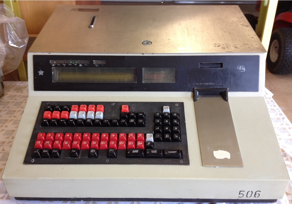
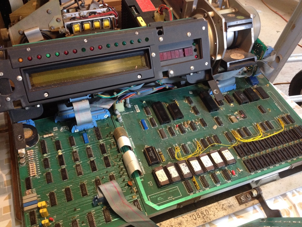
A J22 an ATL historic TIM (Ticket Issuing Machine)
This is an image of a J22 MK2 TIM (Ticket Issuing Machine), manufactured by the long defunct Australian company Automatic Totalisators Limited (ATL). It is not the type of image seen in the glossy sales brochures of a sparkling, straight from the factory floor machine. This is what I call a workhorse TIM having spent about a decade engaged in hard work. It started operation in 1979 in Queensland, subjected to continual transportation from track to track amongst the five race-clubs it, and another 179 J22s serviced. These race-clubs were the Queensland Turf Club at Eagle Farm, the Brisbane Amateur Turf Club at Doomben, the Albion Park Harness Racing Club at Albion Park, the Gabba Greyhound Racing Club at Woolloongabba and the Ipswich Amateur Turf Club at Bundamba. This machine is part of my personal collection of tote memorabilia, which at the time of writing is about a quarter of a century since it was superseded. The photo was taken in a large garden shed where I have set up a small tote history display and I make no apology for this location being evident in this image. As these Queensland race-clubs, were my domain where I worked for over three decades, I know more about the J22s than any other TIM in ATL's product line. By the time the J25s were introduced, we had a department that was very competent at TIM maintenance and I did not have to concern myself much with that part of the business. I could concentrate on the computer room where, apart from performing hardware maintenance, which was still a major task, I became involved in software maintenance and enhancement. For the reader who has arrived here in search of computer history, this page gives a view of microcontroller based terminal design, manufacture and maintenance in the 1970s.
As I know more about the J22 than any other TIM, I have presented more detail on this machine after the image than any of the others in the photo gallery. I have not written the technical parts purely for technologists, hopefully providing sufficient explanation to retain the interest of the not so technical reader, who has at least a modicum of interest in how these machines tick. For the not so technical reader, tick in the last sentence has a deeper technical significance in these machines. tick - tick tock - clock - clock generator - the processor's basic clock, from which other clocks and all sequencing is derived, without which nothing works as the processor is not running.
If you arrived from the Photo Gallery, Click on the image to go back to the photo gallery
If you arrived from navigating the website, use the navigation bar at the bottom of this page.
Photo by Brian Conlon
The J22 was part of a major milestone for the company, as the Brisbane Project to which it belonged, was ATL's first sell pay system. All previous totes were sell only and paying winning tickets was all done manually. For the first time, with this system, the TIM produced machine readable tickets and had a reader that could read the bar code printed on the ticket. The J22 after reading the ticket, transmitted the details to the central tote computers for confirmation and payment details, which when received were displayed to the operator and customer.
Another milestone for the Brisbane Project was that the central tote computers for the first time utilised an operating system. In this case it was DEC's RSX11M (Resource Sharing eXecutive for the pdp11 Multi user version). Executive is an American synonym for Operating System. In previous systems the tote software performed much of the functionality provided by an operating system such as device driving, interrupt service, memory allocation and deallocation, queueing and de-queueing and a myriad of other system services.
The J22 was developed for the Sha Tin Project in Hong Kong. I presume they were to use the J22 Mk1. When this project failed due to inability to deliver on time, the Brisbane Project, which I was working on, became the debut for the J22. The TIM in the image, has a remnant of a sticker attached to the metallic ticket slide, which is on the right hand side of the keyboard leading up into the ticket reader. This remnant of a sticker was the Quality Control Inspector's approval for this machine. Normally these stickers are removed on delivery however this one remained attached for the duration of the machine's lifespan and I have left it attached as an emblem of quality control. It is possible to make out the ATL logo on the remnant of the sticker preceded by the letter Q and followed by the letter C which stand for Quality Control. The inspector's details would have been on this sticker but have faded away.
Another thing I find curious about this machine is the number painted on the lower right of the front, 506. The serial number or the number of the machine produced is often on equipment but this is usually hidden away somewhere on a plate, not displayed so prominently as can be seen here. It is more probable, that this is an electronic address. It is a long time ago and I am not sure. If it is a TIM address, it identifies the electronic address of this machine, that ATL Digital Communications Protocol used, supporting up to 16 machines on multi-drop tri-state lines, making this machine line 5 drop 6. I have to qualify this statement, as it gives the impression that the line number is electronically stored, which is not the case. Only the drop number is used by the protocol, as the front end system already knows the line number that a TIM is communicating on. Often addresses are switch-pack selectable inside the machine, however in the case of the J22, I recollect that the address strapping was soldered on pins in the communications line drop connector plug attached to the machine, to which the communications cable socket connects. With this method of addressing, the address of the machine stays with the machine and in an environment where the machines are moved from track to track the address of the machine needs to be easily identified from the outside, as two machines of the same address cannot be placed on the same line. Even with the address clearly visible on the outside of the machine, some planning is required when transporting machines to a different track to ensure that dual addressing does not occur. From memory, this became a nuisance as more machines needed to be moved and an obvious solution was to remove the address strapping from the TIM plug and place it on the connecting cable socket. This way the electronic address stays fixed with a particular selling window allowing any of the TIMs to be plugged into any position on any of the tracks.
Note the white, very faded ATL logo, identifying the manufacturer, on the right hand side of the black operator display panel with the long Burroughs display on it. This machine also has a star attached to the left hand side, which is not a factory item. There are two things that come to mind regarding this star. Operators often stick things on the machines for a multitude of reasons however the most common is a list of the scratchings and that probably accounts for the bits of sticky tape still visible on the right front of the lid. I have been unable to remove these remnants. Another common reason for a stick-on marker, comes from we of the technical team. Often upgrades were performed and a sticker would be attached to the machine to identify machines that have already been modified, eliminating the need to remove the lid on machines to see if they are already modified. As the machines are distributed across multiple tracks and are moved between tracks some quick method like this, of determining which machines still require upgrading is required to eliminate a significant amount of unnecessary work. The most common modification was to implement new versions of the M6800 device controller program. This required the EPROMs (Erasable Programmable Read Only Memory), which store the M6800 program, to be replaced with ones containing the new version of the firmware. This was done to implement bug fixes or implement new features.
Having mentioned the J22 in the above image having survived the ravages of time, I only know of one other survivor which is in the Powerhouse Museum's collection in Sydney. Most will have been discarded, some may have been abandoned and forgotten somewhere, or joined historic collections I am not aware of. Well that covers where they ended up, the following image shows their beginning, the ATL J22 production line in the ATL factory at Meadowbank.
J22s in production
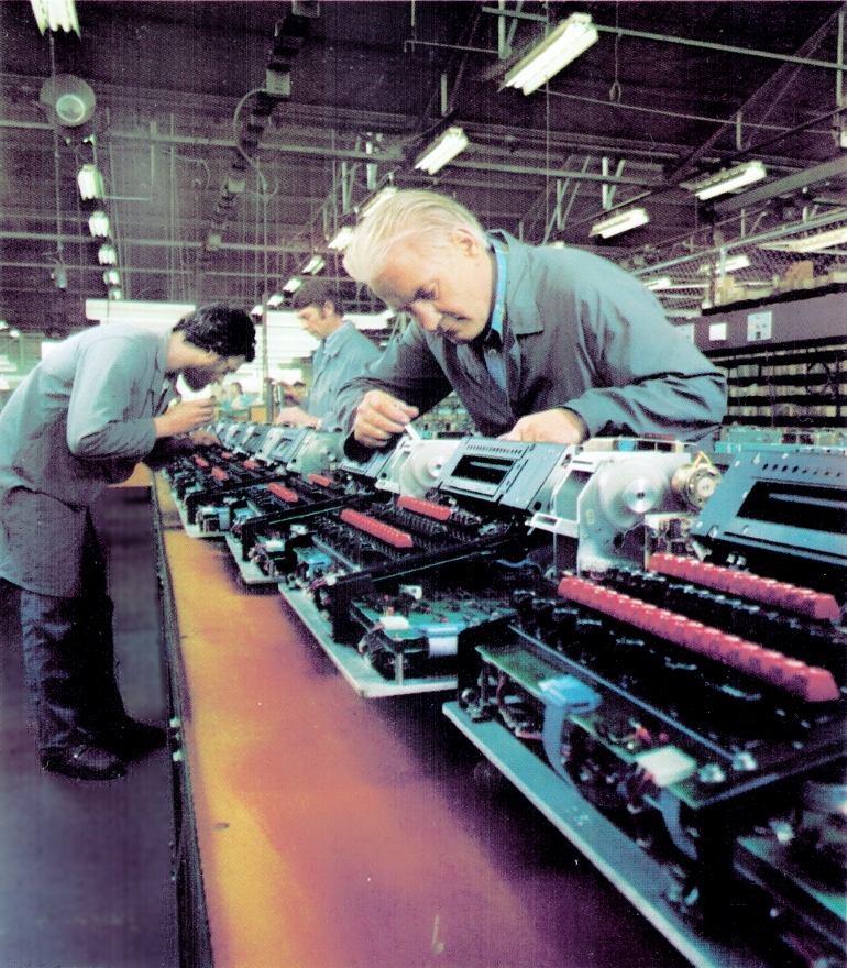
A full sized version of this production line image exists in the Photo Gallery of this website. It is presented here for a complete view, for those readers who are reading pages in sequence, or wading through the index, or perhaps reading this page in isolation.
The J22 image at the top of the page highlights a feature of all ATL electronic totes. The first computer based tote ATL developed, which was for the New York Racing Association, is regarded as one of the first non-stop-systems and this requirement has permeated through all of ATL's totalisator systems. For the layman, a non-stop-system is a design methodology utilised when disruption to service is intolerable. To satisfy this requirement, the systems have to be fault tolerant. In other words they have to continue to function normally, despite any equipment failures. The way this is done is to eliminate all single points of failure by providing redundant equipment. That is why every ATL tote system was a duplex or triplex system. In other words the central tote computers consisting of the transaction processors and front end systems were duplicated or triplicated. As the front end system is duplicated there are two paths of communication between the computer room and every TIM on the race track. That means every TIM is connected to two networks. An example of this duplication can bee seen in the image at the top of this page. In the horizontal black operator display panel, on top of the long Burroughs operator display, on the left hand side, there are two annunciator panels. The left one has 7 lights and the right has 2. The first light in the left hand annunciator panel is a power on light and the next two are POLL 1 and POLL 2. These are two communications status lights. During normal operation they should both be flashing, which means the J22 is receiving polls from both front end systems, in the central computer room. Should any fault condition arise, causing a failure of either network, or either transaction processor, or either of the TIM's communication ports, all bet traffic will still be delivered on the remaining live network, as well as all the other TIM related function traffic. For interest, all the lights in sequence from the left hand side on the J22 are POWER ON, POLL 1, POLL 2, SELL, PAY, 30V FAIL, FAULT, and in the second annunciator panel, PAPER OUT and REJ. SELL indicates Sell Mode, PAY indicates Pay Mode, 30V FAIL indicates a 30 Volt power supply failure and REJ is a contraction of Reject.
|
ATL Sell/Pay system - Tote Topics Summer 76/77
|
J22s in operation Guineas Room Eagle Farm 1979
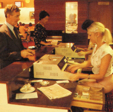
Development work on new products was increased during the year resulting in the release of a ticket issuing machine known as the J22, which incorporates some new and advanced technology. This terminal has created considerable interest amongst racing clubs, being more flexible than competitive products, and designed to achieve significant labour savings in the operation of the totalisator. Development work is continuing at a high priority on other advanced terminals for both on track and off track use as well as low cost computer systems to cater for the needs of smaller racing clubs.
The J22 terminal was the major reason for our success in winning the highly competitive contract with the Royal Hong Kong Jockey Club for a computerised totalisator system, which will be installed at their new Shatin race-track. This system will be the most advanced in the world, and will incorporate many innovative ideas for admission and crowd control, cash management, display boards, and other business information for racecourse operations. A central complex of computers are included in the contract together with the ticket issuing machines, turnstiles, display boards etc.
The A.T.L. Model J22 Sell/Pay Terminal is a high performance transaction terminal designed to meet the demanding criteria essential to an on-course totalisator incorporating the flexibility required by modern operations.
The J22 is capable of selling and paying simultaneously on all pools and values operating at the course. It is this feature which allows a comprehensive totalisator service to be provided throughout the course either by single terminals, operating in restricted areas such as bars and restaurants or by terminals dedicated to specific functions in the main public betting areas.
Reproductions of J22 type tickets are shown on the opposite page. A separate ticket is issued for each pool however this ticket may be of any value and can accommodate up to six runner selections. Further a single ticket is available for an 'each way' bet. A ticket may therefore accommodate equal investments on up to six runners for Win, Place and Each-Way or up to six runner selections for the combination pools, i.e. Quinella, Forecast, Double, Trio or Trifecta. There is no restriction in the number of selections in each leg of the combination pool providing the total does not exceed six. For example, a typical doubles ticket may have 6 & 9 selected in the first leg and 1,8,10 &14 selected in the second leg, which is a total of 8 combinations in the same ticket.
The major components of the J22 are:
Printer
Reader
Keyboard
Operator Display
Customer Display
The Printer is a 7 x 5 dot matrix printer which simultaneously prints 2 lines of 9 mm characters, 1 line of 3mm characters and 2 lines of bar code. The time required to print and issue a ticket is less than 0.4 seconds.
A ticket printed on a J22 Terminal
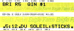
Note: The bar code printed on the ticket had no checksum or CRC. The way errors in reading the ticket were detected was by the use of two bar codes written on each side of the ticket. One bar code is the one's complement of the other. During a read operation the bar code on one side is complemented and the result compared with the bar code read from the other side and if they do not match an error has occurred. Additionally, like the J22 in the image at the top of the page, this ticket seems to have been printed by a well used machine as the print head that produced the middle row of text has a hammer that is not functioning.
The Reader automatically reads the serial number and date recorded in the bar code on the two edges of the ticket. A Ticket presented for payment is fed into the reader slot where it is read, the information is transmitted to the computer system and if a dividend is payable the ticket is mutilated by two punches and returned to the operator and the amount payable is displayed to both the operator and the customer. If for any reason the reader is unable to read the code, the serial number, which is also printed on the ticket in alpha numeric characters may be manually entered by the operator.
The Keyboard is conveniently arranged to encourage operator speed and provides a discreet button for each function. Thus avoiding the possibility of mistakes in entering coded information.
The Operator Display consists of 32 alpha numeric characters to display all information as it is entered through the keyboard. The operator may visually check the details of the transaction before it is transmitted to the computer system. Further information such as customer total and amounts payable are also automatically displayed to the operator.
A Cumulative Total for each series of customer transactions is automatically calculated and displayed to both the customer and the operator. The total is cleared before commencing with a new customer, then the value of each ticket sold is added and amounts payable are subtracted from the cumulative total.
Terminal Operation
The J22 incorporates the speed and reliability of the earlier ATL Ticket issuing Machines together with the all purpose capability necessary to the modern on-course totalisator operation.
While the J22 is capable of selling and paying on all pools simultaneously, certain terminals would be dedicated to specific pools and value to provide fast service windows in the larger betting areas. These terminals would be programme dedicated to reduce the amount of information entered for each transaction.
To sell a ticket the operator first clears the customer total (The customer total can be seen in the image at the rear left hand side of the J22. It is oriented upside down to the operator so that the customer standing behind the machine can read it) then enters, the value, the pool and then the runner selections. The information may then be visually checked on the display (the operator display referred to here consists of the long Burroughs display on the left hand side of the black panel above the keyboard, which is used for general text information, and the shorter display on the right hand side of it which is the operator total, consisting of six seven segment displays representing dollars and two seven segment displays for the cents ) and if correct it is then transmitted to the central computer. If it is incorrect the operator can clear the entry.
The central computer on receiving the details of the bet will check that no errors have occurred in transmission and then check that the bet is valid e.g. that the pool is operating, that betting is 'on', that the selected runners are not scratched. If the bet is invalid the computer will transmit a message to the terminal which is then displayed to the operator. (On the Burroughs display)
If the bet is valid the computer will assign it a unique serial number and record the details in core memory (Do you remember core memory? This really dates the system!) for odds and dividend calculation, on disc memory for payout, and on the daily history tape as a permanent record. The terminal cash status record is also updated. This full record of every bet is kept by both computers.
When the bet is recorded the information is then transmitted to the terminal together with the serial number and the ticket is printed. The details printed on the ticket are theretofore identical to those recorded by the central computer. The value of the ticket is added to the customer total on both the operator and customer displays.
A ticket presented for payment is inserted into the reader slot (which can be seen under the black surround at the top of the rectangular, shiny metal ticket slide on the right hand side of the keyboard - the ticket is placed flat on this slide then pushed up into the reader) by the operator where it is then transported through the reader and the bar code on the edge of the ticket, containing the serial number and date is read and the information is transmitted to the central computer.
The computer checks that no errors have occurred in transmission and then locates the serial number on its disc files. The full details of the bet recorded with the serial number are then checked and the computer determines whether a dividend is payable, and the amount, if a dividend is due the computer records that it is paid and updates the terminal cash status file. Further, the terminal cash status is compared with the amount payable to ensure that the operator has the cash to make the payment.
The dividend is then transmitted to the terminal where it is displayed to the operator, and is subtracted from the customer total. The ticket is cancelled by mutilating the bar code with two holes and the ticket is returned to the operator. If the operator does not have the cash to pay the dividend, the nearest cashier is automatically notified so that the cash can be quickly provided. (This tote system had an integral cash control system.)
If the reader is unable to read the ticket the operator may then manually key in the serial number to initiate the transaction.
|
Sample of the J22 M6800 Source code
|
The J22 presented another milestone for the company, in that it was the first terminal to be implemented using a microprocessor. Most readers will probably be familiar with the term microprocessor, as they form the basis of personal computers and smart-phone devices. Simplistically they implement the functionality of a CPU (Central Processing Unit) of a digital computer in an integrated circuit. The non technical reader will probably be unaware that microprocessors can fulfil the function of a device controller as well as form the basis of personal computers. In this role rather than executing instructions to implement an operating system they execute instructions to provide the control and sequencing signals to simplify the electronics required to implement some custom built device. This utilises the microprocessor as an intricate electronic component. To guarantee component level maintenance of a TIM like the J22 one has to have a copy of the source code listing of the firmware the microprocessor is executing as this completes the definition of its functionality. All integrated circuits have a functional specification that details exactly how it works making it possible to determine if it is functioning correctly. With a microprocessor however, the functional specification of the hardware, excluding the significant architecture specification, only defines the purpose of each of the contacts on the integrated circuit for instance Address, Data and Control lines, DMA (Direct Memory Access) and Interrupt signals etcetera. To determine what predominant sequence the microprocessor is performing at any instant however, you need to have the details of the firmware routines and subroutines which completes the picture. Most faults can be isolated and rectified without the firmware listing however for some of the more elusive and difficult to analyse problems the source code will provide the answer. I recall on one occasion, when the provided firmware diagnostics did not adequately exercise a particular circuit, resorting to writing a diagnostic routine to specifically generate signals in the failing circuit, suitable for analysis with a CRO (Cathode Ray Oscilloscope) to identify the faulty component. Implementing diagnostic code for a microprocessor in a firmware environment is tedious as it requires the blasting of PROMs to implement it. This was far easier and was quite common, on the Mini Computer central systems, which had consoles where small diagnostic routines could be entered into memory in machine code and executed. Early consoles had toggle switches, where instructions were entered in Binary and later consoles understood Octal or Hexadecimal numbering systems simplifying the task.
Having mentioned that sometimes it is necessary to have a copy of the source code to analyse difficult problems associated with microprocessor controlled devices, the same can be said for other programmable electronic devices for instance GALs (Generic Array Logic), where you need access to the GAL equations to determine if the specific GAL is operating properly. A similar situation exists for PLAs (Programmable Logic Arrays) and PALs (Programmable Array Logic). Whilst on the subject of the J22 being an example of a microprocessor controlled device, I have included the following sample of the listing of the J22 firmware. I have included a small segment of a couple of subroutines that do the simple task of printing a test ticket. All this firmware is written in M6800 Assembler Language. This is the lowest level programming language requiring a good understanding of the architecture of the machine particularly the instruction set and addressing modes. For the technologists, it is interesting to note that the M6800 was an attempt to implement PDP11 architecture in a microprocessor. It did not completely achieve this however the PDP11 architecture is recognisable in the M6800. One of the big differences is that the M6800 is an accumulator class computer. On this subject, I found it curious in my latter years in the industry, to find competent technologists, who did not believe it is possible to build a digital computer without the use of a microprocessor! Most of the Mini Computer era, the Mini Computers, Mainframes and Supercomputers, were much more hardware intensive classes of machine, implemented without microprocessors. There were three generations of computers prior to microprocessors being introduced in the Fourth Generation. I spent decades with Third Generation computers. The use of microprocessors exploded with the advent of personal computers. Classes of computer above Microcomputer prior to this, did not utilise microprocessors, as the early versions of these were too slow for the purpose. The history of digital computers can be traced back through implementations utilising ever decreasing levels of integration to logic gates built of discrete component diodes transistors and resistors with logic families like RTL (Resistor Transistor Logic) DTL (Diode Transistor Logic) and TTL (Transistor Transistor Logic) before they became implemented in ICs. And prior to the advent of the transistor, gates were built out of valves.
The test ticket produced by the following subroutines produces a ticket that is similar to the ticket in the image above. It differs in that the top line of text reads SELF-TEST TICKET the middle row reads ABCDEFGHIJKLMNOPQRSTUVWXYZ and the bottom row reads 0123456789. This facility allows the machine to print a test ticket, which cannot be confused with a live ticket. Additionally the test ticket produced can be used to test the reader as well. Fear not, I am not going to turn this into a tutorial on M6800 assembler, which I would not be comfortable with anyway, as my expertise lies in PDP11 and VAX assembler. I had a lot more exposure to them and I have not had anything to do with M6800 architecture since the J22s were retired. I have added a few comments below however.
The M6800 J22 Program Extracts
Extracted comment at the beginning of file J22FUNC.M68
| * | *************************************************************** | * |
| * | | * |
| * | | * |
| * | | * |
| * | | * |
| * | | * |
| * | | * |
| * | J22 MARK II PROGRAM | * |
| * | | * |
| * | FOR THE BRISBANE TOTALISATOR SYSTEM | * |
| * | | * |
| * | | * |
| * | | * |
| * | | * |
| * | PROGRAM WRITTEN AUGUST-SEPTEMBER 1978, | * |
| * | | * |
| * | BY ROB HOLGATE AND BOB PUNCH. | * |
| * | | * |
| * | | * |
| * | MODIFIED JUNE 81 FOR MACAU J25 LOOK- | * |
| * | ALIKE, BY S.STEPHENSON. | * |
| * | | * |
| * | *************************************************************** | * |
I recall all the names mentioned above. I remember Simon Stephenson very well. We spent many late nights at deserted racetracks together, rectifying problems during the early operations of the PDP11 based tote systems, introduced on-course in Queensland in February 1979. I also remember the names Rob Holgate and Bob Punch well, however I do not recall whether I met them. I am pretty sure that Rob was a Doctor of Engineering and his doctorate was often mentioned in conjunction with his name.
The following subroutine STPRT is called from the Function Module - Program Block, at label F23, containing code which handles the activation of the TEST key, commented as TEST KEY: TO PRINT A TEST TICKET. I have not included that code here as this is only intended as an introductory sample and could easily become voluminous if allowed to grow. The TEST key mentioned is visible in the J22 image above. It is a black key in the bottom row sixth key from the left.
Extracted comment preceding the STPRT Subroutine in the STEST Module - Program Block
| *----------------------------------------------------------------- |
| * ***** SUBROUTINE STPRT ***** |
| * SUBROUTINE TO TEST THE TICKET PRINTER. |
| * THE CHARACTER PRINTED ON TEST TICKET |
| * IS SHOWN IN THE "FCC" TABLE FOLLOWING |
| * THE SUBROUTINE. THE BAR-CODE TO BE |
| * PRINTED IS 00010111000101110001011100010111. |
| * THIS TEST TICKET PRINTED CAN BE USED |
| * FOR READER TEST. |
| *----------------------------------------------------------------- |
Extracted STPRT Subroutine follows on from above comment
| Label | Instruction | Operand | Comment |
|---|
| | | |
| STPRT | PSHA | |
| * | | | |
| LDAA | #1 | |
| STAA | STCYCL | * SET CYCLING FLAG |
| BRA | STPRT0 | |
| * | | | |
| STPRT2 | BSR | STPRINT | *PRINT A SELF TEST TICKET. |
| * | | | |
| STPRT0 | LDAA | FLFLAG | *IF PRINTER FAULT HAS |
| BEQ | STPRT3 | OCCURRED, DON'T START |
| JMP | CYCL1 | ALLOW ANY MORE PRINTS |
| * | | | |
| STPRT3 | TST | PRFLAG | *TEST IF PRINTER IS |
| BEQ | STPRT2 | FREE |
| LDX | #STPRT2 | *IF BUSY, SET PRINT |
| STX | STPADR | REQUEST FLAG. |
| INC | STPREQ | |
| * | | | |
| PULA | | |
| RTS | | |
| PAGE | | |
As can be seen there is a comment field on the right hand side in the M6800 code. There is also a comment specifier the * and anything on a line following a star is ignored by the assembler, hence a * at the beginning of the line without any following text is there purely for spacing and makes the code easier to follow. A * character in the comment field has been used here to identify to the reader the beginning of a multi line comment.
The line including the instruction BSR STPRINT above calls the subroutine defined below. BSR is an instruction mnemonic for Branch Sub Routine and the operand STPRINT is the address of the subroutine identified by the label STPRINT below.
I mentioned the M6800 being an accumulator class machine. The use of the accumulator can be seen in the two above instructions LDAA (load Accumulator A) and STAA (Store Accumulator A). In other words in this example, the accumulator is used to access main memory. Put a 1 in the accumulator then write that to memory location labeled STCYCL. The PDP11 is a bus structured machine and can access memory directly. It is a two address machine and is capable of performing main memory to main memory moves in one instruction.
Extracted comment preceding the STPRINT Subroutine directly following last line above with PAGE
| *----------------------------------------------------------------------- |
| * THIS SUBROUTINE PRINTS A 'SELF TEST TICKET' |
| *----------------------------------------------------------------------- |
Extracted STPRINT Subroutine follows above comment
| Label | Instruction | Operand | Comment |
|---|
| | | | |
| STPRINT | PSHA | | |
| PSHB | | |
| LDAA | PRFLAG | | |
| BNE | STPRT5 | | |
| * | | | | |
| LDX | #$1717 | *LOAD BAR-CODE STORAGE | |
| STX | BAR | WITH DESIRED PRINT-OUT | |
| STX | BAR+2 | CODE. | |
| STX | BAR+4 | | |
| LDAA | #48 | *LOAD NUMBER OF BARS. | |
| STAA | NBAR | | |
| * | | | | |
| LDX | #PBUF1 | *MOVE SELF TEST TICKET | |
| LDAA | #28 | TEXT STRINGS TO THE PRINTER | |
| JSR | ROMSG1 | BUFFERS. | |
| * | | | | |
| LDA A | SIGNON | IF SIGNED ON THEN PRINT | ***SRS |
| BEQ | STPR01 | LINE AND DROP | ***SRS |
| JSR | PMIDL | FORM LINE AND DROP | ***SRS |
| LDA A | #ETX | | ***SRS |
| STA A | PBUF2+14 | | ***SRS |
| BRA | STPR02 | | ***SRS |
| * | | | | |
| STPR01 | LDX | #PBUF2 | | ***SRS |
| LDAA | #30 | | |
| JSR | ROMSG1 | | |
| * | | | | |
| STPR02 | LDX | #PBUF3 | | ***SRS |
| LDAA | #32 | | |
| JSR | ROMSG1 | | |
| LDAA | #$08 | | |
| STAA | PARAM | | |
| JSR | PRINT | *PRINT SELF TEST TICKET | |
| * | | | | |
| STPRT5 | PULB | | | |
| PULA | | | |
| RTS | | | |
| * | | | | |
| INCH | PSHA | | | |
| PSHB | | | |
| * | | | | |
| LDAA | PRFLAG | *IGNORE IF PRINTER OR | |
| ORAA | RDFLAG | READER NOT FREE. | |
| BNE | INCH2 | | |
| LDAA | #1 | *MARK AS 'CYCLING' | |
| STAA | STCYCL | TEST. | |
| INCA | | | |
| STAA | PRFLAG | *SHOW PRINTER NOW BUSY. | |
| LDAA | RIBBON | *START PRINTER AND | |
| ORAA | #$20 | RIBBON MOTORS | |
| LDX | #INCH3 | | |
| STX | TAADDR | | |
| LDX | #IGO | *DELAY FOR 0.5 SEC | |
| INCH1 | STAA | PMOP | | |
| LDAB | #MOTOR | | |
| SEI | | | |
| JSR | IOWR | | |
| CLI | | | |
| JSR | NEGX | | |
| STX | TIMERA | | |
| INCH2 | PULB | | | |
| PULA | | | |
| RTS | | | |
| * | | | | |
| INCH3 | PSHA | | | |
| PSHB | | | |
| CLRA | | | |
| LDX | #INCH4 | *START TIMER WHILE MOTORS | |
| STX | TAADDR | MOTORS STOP AND | |
| LDX | #ISTOP | PRINTER PAUSES. | |
| BRA | INCH1 | | |
| * | | | | |
| INCH4 | CLR | PRFLAG | *FREE THE PRINTER. | |
| CLR | STCYCL | *ENABLE NORMAL KEYBOARD | |
| RTS | | RESPONSE. | |
| * | | | |
| PAGE | | |
Note the ***SRS comments in the comment field of several lines above. These are modification markers. In the first introductory comment of this extract, it identifies a change made by Simon Stevenson made in June 1981. His initials appended to these lines indicates these are part of his modification. I have done a lot of software enhancements and bug-fixes to the VAX based transaction processor software and consequently that has many of my change markers in it. This change tracking makes it easy to identify what changes were made when. This is important, as the unmodified code, as it has been running for some time, is likely to be quite bug free. Any newly discovered problems are most likely to be in the modified code. This change tracking makes it easy to look in the places where new problems are likely to have arisen, rather than wading through what is usually masses amounts of working code as well.
Back to the subject of the M6800 accumulator, in the above extract segment, the use of the accumulator to perform ALU (Arithmetic and Logic Unit) operations can be seen. LDAA PRFLAG loads Accumulator A with a one bit status flag, then ORAA RDFLAG performs a logical OR operation of the contents of Accumulator A with another one bit status flag. The following BNE (Branch Not Equal to zero) branch is taken if either of the flags are set. The PDP11 is not restricted to an accumulator in performing ALU operations.
I have not provided the definitions of referenced variables constants and buffers as they are located in a variety of places and this is supposed to be a small sample. I have however included the following example as it defines the text strings that appear on the test ticket which needs no further explanation. Intervening definitions in the listing have been omitted.
Extracted from ROMTXT MODULE - TABLE BLOCK
| Label | Instruction | Operand | Comment |
|---|
| | | | |
| ROM28 | FCB | $00 | |
| FCC | /SELF-TEST TICKET/ | |
| FCB | ETX | |
| ... | ... | ... | ROM29 definition omitted |
| ROM30 | FCC | /ABCDEFGHIJKLMNOPQRSTUVWXYZ/ | |
| FCB | ETX | |
| ... | ... | ... | ROM31 definition omitted |
| ROM32 | FCB | $00 | |
| FCC | /0123456789/ | |
| FCB | ETX | |
FCC is an assembler directive, to Form Constant Characters with the following text. The FCB on the next line, is an assembler Form Constant Byte directive, that appends an ETX (End of TeXt) character to mark the end of the test ticket string.
To give some idea of the work involved in writing firmware for a device controller, the complete J22 listing from which the above samples were extracted, is printed on continuous form 132 column tractor paper feed printer paper. It has its own binder and consists of 369 pages. To put this into context, the samples I have presented here fit onto two pages. This listing would fit on 80 column paper, most of the printers I encountered catered for 132 columns as this was required for the higher level languages which had longer lines particularly when using structured higher level languages because of the indenting. During my time, although significant parts of the tote transaction and application processor software was written in assembler due to efficiency and performance considerations the major part of these systems was written in structured higher level languages.
In the following image, we can see where the J22 M6800 Program, which has been sampled above, is stored as well as see where the M6800 Microprocessor, which executes this code is located in the J22.
Inside the J22 with covers removed
Above is an image showing the workings of the J22. It has the top shiny lid removed, which has a key lock and lifts off. Once this is removed it is a simple job to lift the surrounding shroud off as well. The Keyboard is hinged and there are two screws, with knurled knobs on them, to make them easy to unscrew, using thumb and fingers and the keyboard then swings forward, out of the way. A corner of the printed circuit side of the keyboard and the right hand keyboard hinge can be seen at the bottom right corner of this image. Attached to the bottom of the black operator panel, at the left and right extremities, there are two narrow black brackets protruding over the printed circuit boards below. These are the support brackets for the top of the keyboard when it is swung into place and the threaded holes for the keyboard securing screws can be seen in them. The blue ribbon cable at the bottom centre of the above image connects the Keyboard to the Peripheral Interface Board.
A significant reason for this image being here is to show what is executing the instructions in the J22 Firmware example above. Look at the right hand keyboard securing bracket mentioned above, the M6800 Microprocessor is the long black IC (Integrated Circuit), almost parallel and to the left of the bracket. The printed circuit board the microprocessor is connected to is the Processor Board. You can clearly see the name in the bottom left corner of this board, inside the white rectangle, along with the ATL logo. This and other ICs on this board including the RAM (Random Access Memory) and EPROMs (Erasable Programmable Read Only Memory) are sitting in IC sockets. This allows for easy replacement of the parts. The sockets are soldered onto the PCB instead of the ICs and the legs, which are the electrical contacts of the ICs are pushed into the sockets. This does introduce a source of problems, as the contacts over time can introduce high resistance in their connections requiring the component to be removed and the contacts of the IC and the socket cleaned. In the case of the EPROMs the sockets are essential otherwise it would require a very labour intensive effort to change the firmware which happens most often when a new system is introduced and bugs in the firmware are eliminated. Apart from this, enhancements are often implemented during the lifespan of a TIM and the sockets justify their implementation again. Having mentioned sockets introducing a problem, the lack of sockets can also be problematic, as without them components have to be desoldered so the faulty component can be removed and the new component's contacts need to be soldered to the pads on the circuit tracks. If too much heat is used, whilst desolering or soldering, the printed circuit pads can lift off the board, or even worse break away from the rest of the track, making it difficult to reconnect the IC leg to its associated track. Additionally too much heat applied whilst soldering can damage the new component. Finally, the MOS (Metal Oxide Semiconductor) and CMOS (Complimentary Metal Oxide Semiconductor) logic families that the large scale integration components utilised at the time, were prone to damage from static electricity. The more careless handling of the IC, particularly if not using an earthed wrist strap, the more likely the new IC will be damaged. Having mentioned the firmware, the EPROMs in which the Firmware and hence the code in the example above is stored are visible in this image. They are the 7 large ICs near the front of the Processor PCB, to the right of the centre of the image, with the notes on them. These notes identify the location, TIM, the address at which the EPROM belongs in hexadecimal, the version of the firmware and the date. The notes read:
- BNE 22V - C000 - v1.7 8-9-87
- BNE 22V - B800 - v1.7 8-9-87
- BNE 22V - B000 - v1.7 8-9-87
- BNE 22V - A800 - v1.7 8-9-87
- BNE 22V - A000 - v1.7 8-9-87
- BNE 22V - 9800 - v1.7 8-9-87
- BNE 22V - 9000 - v1.7 8-9-87
The notes on the above EPROMs actually serve a second purpose. They also keep light out of the EPROM's erasing window. The labels are stuck over a window on these integrated circuits, which allows light to enter. The ultraviolet component of this, erases the contents of the EPROM. When these EPROMs are to be reused, by writing a new version of the program to them, they have to be erased first. This is done by removing the labels and storing them under an ultraviolet lamp. The first thing that needs to be done before blasting them with the new program, is to ensure that they are actually blank after being erased, by checking that every bit in every address in the EPROM is equal to zero. Later, EEPROMs (Electrically Erasable Programmable Read Only Memory) became available, eliminating the need for UV erasure. From the hexadecimal addresses of these EPROMs, which start at 9000, it can be seen that they increment at 800 hexadecimal intervals, which in decimal is 2048 or 2 kilobytes capacity per EPROM, giving 14 KB total Read Only Memory for program storage, across the 7 EPROMs.
There are two printed circuit boards visible beneath the black operator display panel. The larger one on the right hand side is the Processor Board and contains the components referred to in the last paragraph. The smaller board on the left is the Peripheral Interface, or Peripheral Control Board which has the ATL logo clearly visible on the top of it.
On the left hand edge of the Peripheral Interface Board, near the bottom of the image above, are four rectangular components. The top two are grey, the next blue followed by another grey one. These are variable resistors or Trimpots as referred to later in this page. These are used for making adjustments to electronic signals. There are small brass coloured projections at the left hand end of these components, which have small flat screw heads. There is a plastic tool that looks like a pencil or small pen, which often had a clip on it, like a pen cap, so that it could be carried and secured in a shirt pocket. It was called a Tweaker and was a small screwdriver. The plastic body of this tool often extended down around the screwdriver blade to provide as much insulation as possible to keep the blade from making contact with other components in the electronic circuit being adjusted. This minimised the risk of causing damage, resulting from accidentally short circuiting parts of the circuitry with the Tweaker. This tool would be used to wind the screw adjusters on the left hand side of the Trimpots, which alters the resistance of the Trimpot, whilst observing test equipment, usually a multimeter or CRO (Cathode Ray Oscilloscope), to achieve the optimum performance of the circuit.
At the top, left of centre of the image above, is a metal assembly with four yellow rectangles in it. This is the Walther J22 Ticket Printer. The mechanical engineering drawing for this printer can bee seen in the image below titled The J22 Printer Assembly drawing. The yellow rectangles are four of the hammer solenoids that drive the hammers that apply ink from the ribbon onto the paper. There are another four of these solenoids underneath this row and there are another eight similar solenoids on the opposite side of the printer. One of these eight solenoids on each side, drives its respective upper or lower bar code hammer. These hammers impart the dash like binary markings at the top and bottom edges of the ticket, as seen in the image above titled A ticket printed on a J22 Terminal. All the other hammers, two banks of seven on either side, impart dots to the paper, which form alphanumeric characters, that constitute the upper and lower text lines on the ticket next to the bar codes, as seen in the image of a J22 ticket previously mentioned. In between the side plates of the printer containing the yellow solenoids is the Walther Print Head. This prints the middle line of text shown on the image of a ticket above. The information in this line, from memory is the day and month, what looks like an E which could be a single character location specifier, in this case Eagle Farm, the address of the terminal that printed the ticket, the ticket serial number and the unit of investment in dollars and cents. The Walther Print Head has a shape similar to a Viking's axe where the lines from the blade to the handle are concave and the blade surface is convex. That is where the similarity ends! The blade end of the Walther Print Head is not sharp, but is the widest section of the head where the hammer solenoids are installed in a convex arc. Where the handle would be, is the thinnest part and is the point where all the hammer wires converge, to form the print matrix. The hammer wires associated with the solenoids that are at the top and bottom extremities of the analogous axe blade, have the most curvature. This axe shaped head is installed vertically between the two side plates of the printer. Above the horizontal top of the near printer side plate in the image above, which can be seen above the four yellow solenoids and the horizontal red wires, you can just see the tip of the arch of the Walther Print Head, peering over the top of the side plate. If this were an axe, the arc of the convex blade is on the right hand side and the concave arc to the handle is on the left of this peak. To the left of the arch of the Walther Print Head, a tubular piece of metal rising to the right at about forty degrees to the top of the printer side plate can be seen. This is the Printing Head Latch, which is a quick release device, which allows the whole right hand section of the printer containing the yellow solenoids, to drop down revealing the paper contact surface of the printer. Curiously this old J22 still has ticket paper sitting in the printer paper transport system.
Having mentioned the not so obvious, top of the Walther Print Head, I have a not so easy to see item in the printer. It is the left hand one of two ribbon spools. These spools are like the ribbon spools of a typewriter and serve the same purpose. Why the typewriter analogy I perceive you ask? I hate to admit it, however I have used typewriters! First, to find this spool, we must locate the last red light, on the right hand side, in the row of yellow, red and green LEDs (Light Emitting Diode) in the annunciator panel. The annunciator panel is the row of LEDs above the Burroughs display, which is the long horizontally oriented, operator display device. The last red LED is followed by five green LEDs to its right. From the last red LED, move vertically up the image. At the top of the black operator display panel there is a thin horizontal green line visible. This is the top edge of the Burroughs Display board. Moving further up, just past the top of the Burroughs Display board edge, there is a small silvery grey projection above the board. This is the top of the spindle of the near ribbon reel. Looking between this spindle and the horizontal line of the bottom of the yellow solenoids, you can make out the arc of the far side of the ribbon reel. This is a very low angle view of the ribbon reel, so around one hundred and forty degrees of the ribbon reel is visible in the small distance between the top of the Burroughs Display board and the bottom of the hammer solenoids. The span of the arc as it disappears under the Burroughs Display board, is a little wider than the projected, left and right hand ends of the yellow hammer bank of solenoids, onto the Burroughs Display board green line. The ribbon spools are visible in the image below titled The J22 Printer Assembly drawing in the plan view at the bottom of the drawing.
To the right of the printer in the above image is a black box with a red label on it. This is the Power Supply.
Further to the right, and flush with the front of the black Operator Display Panel is the Welch Allyn Reader assembly. This reader, reads the barcode on the tickets produced by the printer described above. The ticket intake chute and the ticket exit chute above it, which are both black are clearly visible. On the right hand side of the reader, at the far right of the J22, extending up from the intake chute height, the printed circuit side of the Reader Interface Board can be seen, which is mounted vertically. It has two ribbon cables attached to it.
One last thing is worthy of mention in the above image. Have a look at the yellow wires above the row of EPROMs and RAM IC sockets to the right of the EPROMs. This is an example of Wire-wrap, a wiring method that used to be quite common, particularly when developing circuits and building prototypes, during the era prior to computer aided design. Wire-wrap is a name describing the means of making connections between the wire and the connection pins. This simply involves using a Wire-wrap tool to tightly wrap the wire around the pin. It was used in circuits which are likely to be changed at some stage. Here in the J22 they are implementing configurable connections, like Baud Rate selection and address range of RAM ICs installed. Wire-wrap was often used by design engineers to design new circuits. As design has an element of trial and error, it is beneficial to be able to change the circuit easily. A Wire-wrap circuit is built by pushing Wire-wrap pins through an insulating board, called a Breadboard or Protoboard. Electronic components are connected to the pins on one side of the board, and the interconnections between the components are made on the opposite side using Wire-wrap. This usually results in a mass of wires on the wiring side of the insulating board. If the circuit does not perform as expected, it is an easy matter to undo the Wire-wrap connection and make a new connection. The Brisbane tote project, to which the J22 TIM at the top of this page belonged, had central computer systems, that had CCTV display generators implemented utilising Wire-wrap. I initially expected to have many connection related problems with these CCTV generators. I eventually realised that the wire-wrap connections are very reliable. With the second generation of tote system after this one, we used a type of TIM called the TIM91. After a few years of operation, multiple instances of open circuit faults in the printed circuit tracks were encountered. These were easily repaired, however it was time consuming to identify the location of these breaks, as most of the time they were not visually obvious. They had to be identified by analysis with a CRO to identify a faulty signal and then the quickest way to identify the exact location of the break was by performing resistance measurements along the associated stretch of track. It was then a simple task to bridge the break with a short piece of wire and solder. I had not seen anything like this prior or since. I encountered PCB track open circuit faults, when PCs came on the scene, where a battery had leaked corrosive chemicals on the tracks, but these faults did not involve leaking batteries. Some other corrosive action, or some susceptibility to movement, or possibly a problem with the conformal coating was responsible. I then realised that Wire-wrap could be more reliable than printed circuit boards as we never experienced a single Wire-wrap connection problem.
|
The J22 Mk II Technical Manuals
|
The J22 manuals for this project are titled Brisbane Technical Manual EM 288 Part 1 and Part 2. As in the last section, I only intend to give a glimpse of these manuals as they are quite extensive. Part 1 contains a few drawings and diagrams, which support a mass of technical descriptions and procedures. Part 2 primarily contains circuit diagrams, mechanical drawings and parts lists. I have included the table of contents of Part 1 as well as some extracts to indicate what it contains. The manuals are typical of electronic equipment manuals of the time.
TABLE OF CONTENTS
| SECTION 1 | INTRODUCTION AND BRIEF DATA | PAGE |
|---|
| | |
| 1.1 | INTRODUCTION | 1/1 |
| | | |
| 1.2 | BRIEF DATA | 1/3 |
| 1.2.1 | Dimensions and Weight | 1/3 |
| 1.2.2 | Electrical Data | 1/3 |
| 1.2.3 | Environment | 1/3 |
| 1.2.4 | Paper Specification | 1/3 |
| 1.2.5 | Ticket Specification | 1/4 |
| 1.2.6 | Storage Conditions | 1/4 |
| 1.2.7 | Ribbon Storage Life | 1/5 |
| 1.2.8 | Communications | 1/5 |
| | | | |
| SECTION 2 | INSTALLATION | |
|---|
| | | |
| 2.1 | UNPACKING | 2/1 |
| | | |
| 2.2 | INSTALLATION | 2/1 |
| 2.2.1 | General | 2/1 |
| 2.2.2 | Fuse Installation | 2/2 |
| 2.2.3 | Reader Installation | 2/2 |
| 2.2.4 | Printer Installation | 2/2 |
| 2.2.5 | Ribbon Installation | 2/3 |
| 2.2.6 | Paper Roll Installation | 2/3 |
| | | |
| 2.3 | PREPARATION FOR OPERATION | 2/4 |
| 2.3.1 | Mains Voltage Settings | 2/4 |
| 2.3.2 | Mains Lead | 2/5 |
| 2.3.3 | Mains Lead Connection | 2/5 |
| | | |
| | ii |
| | |
Following is Section 1.1 INTRODUCTION, Page 1/1, as shown in the table of contents above:
The J22 Mark II Ticket Issuing Machine (TIM) is a microprocessor-controlled terminal, designed for on-line operation with a host processor within a computer-based totalisator system.
The terminal caters for a wide variety of transactions, details of which are entered by the operator by means of a keyboard. An alpha-numeric display enables the operator to monitor and change the transaction details as they are keyed in. The details are subsequently transmitted to the host processor for validation and, if valid, a printed ticket is delivered from an opening in the top cover of the TIM. The bet details are printed in a 5x7 dot matricx alpha-numeric form. In addition, a binary-coded complementary bar code, corresponding to the printed information, is printed on both lengthwise edges to enable the ticket to be "read" when it is inserted into the reader.
If the transaction details are incorrectly keyed-in or the transaction is illegal, the TIM microprocessor or the host processor rejects the transaction, sounds an alarm and transmits an appropriate response message to the operator's alpha-numeric display. The operator then carries out the remedial action. The amount of the transaction is displayed on two Cash Total Displays, one on the operator side of the TIM and one on the customer side. A RECEIVE (green) LED indicator on the operator's display and a PAY (red) LED indicator on the customer's display are illuminated to indicate that the customer is to pay the total amount displayed. The operator's PAY (red) indicator and the customer's RECEIVE (green) are illuminated if the customer is to receive the total amount displayed.
Winning tickets are inserted into a ticket reader opening where they are sensed and the feed mechanism started. The mechanism transports the ticket past the bar code reader, then stops and waits. The decoded bar code details are transmitted to the host processor for validation. If the ticket is valid, it is fed out of an exit opening, the winning amount is then displayed on both Cash Total Displays, and the appropriate PAY and RECEIVE indicators are illuminated.
If the bar code is illegible, contains invalid data, or has been previously paid, an appropriate response message is displayed on the alpha-numeric display, and the ticket is ejected. If only the bar code is illegible, the ticket serial number (TSN) can be manually entered by means of the keyboard to enable the ticket to be processed. End of Section 1.1:
There are several pages in the Brief Data, section 1.2 of the manual as referred to above, however I have only included the Dimensions and Weight extracted from section 1.2.1. Width: 559mm Depth: 559mm Height 283mm and Weight: 39Kg. In the Melbourne Cup chapter of this website, Graeme Twycross, who worked on the Julius Totes in Victoria, relates, what appeared to be a widely held belief within the company, that to make an item portable, you just added handles to it, regardless of the weight and dimensions. The J22, although it weighs 39Kg, has two handles on it, making it portable by ATL's standards! I believe I suffered a hernia in retirement, as a result of moving a J22 and a J8 from my garage to the garden shed despite the fact that I was not silly enough to move them on my own and my son Ian was holding the other handle. He too thought he suffered a hernia shortly after, however as time elapsed, this turned out not to be the case. It is ironic, that I did not suffer a hernia from the J22s and similar machines when I worked with them, although I never had to move them far. We had staff dedicated to moving these machines from track to track, who invariably were endowed with a heavier build than mine.
TABLE OF CONTENTS (cont'd)
| SECTION 3 | TECHNICAL DESCRIPTION | PAGE |
|---|
| | |
| 3.1 | GENERAL | 3/1 |
| | | |
| 3.2 | COMPOSITION | 3/1 |
| | | |
| 3.3 | BRIEF DESCRIPTION | 3/2 |
| | | |
| 3.4 | PROCESSOR BOARD | 3/4 |
| 3.4.1 | Microprocessor Unit | 3/5 |
| 3.4.2 | Programmable Timer Module | 3/7 |
| 3.4.3 | Peripheral Interrupt Request Circuit | 3/8 |
| 3.4.4 | Priority Interrupt Controller | 3/9 |
| 3.4.5 | Random Access Memory | 3/10 |
| 3.4.6 | Programmable Read Only Memory | 3/11 |
| 3.4.7 | Peripheral Interface Adaptor | 3/12 |
| 3.4.8 | Bit Rate Generator | 3/12 |
| 3.4.9 | Asynchronous Communications
Interface Adaptor | 3/14 |
| | | |
| 3.5 | PERIPHERAL CONTROL BOARD | 3/16 |
| 3.5.1 | Reader Interface | 3/16 |
| 3.5.2 | Printer Interface | 3/17 |
| 3.5.3 | Keyboard | 3/20 |
| 3.5.4 | Operator/Customer Cash Total Displays | 3/21 |
| 3.5.5 | LED Indicator Display | 3/21 |
| 3.5.6 | Burroughs Display | 3/22 |
| | | |
| 3.6 | KEYBOARD | 3/22 |
| 3.6.1 | Meeting Keys | 3/22 |
| 3.6.2 | Pools Keys | 3/23 |
| 3.6.3 | Value Keys | 3/23 |
| 3.6.4 | Runner Number Keys | 3/23 |
| 3.6.5 | Control Keys | 3/24 |
| 3.6.6 | Circuit Description | 3/26 |
| | | |
| | iii |
| | |
The Priority Interrupt Controller, section 3.4.4, mentioned above in the Table Of Contents, can easily be seen in the image above. It is the IC in a socket above the left hand EPROM of the seven EPROMs in a row with labels on them. It is identified by the writing on it MC8507P. I am not going to get into a discussion of the interrupt system, however for those who know what vectored interrupts are, this PIC accesses the EPROM below it to retrieve the vector to the appropriate interrupt service routine when an interrupt occurs. For the not so technical readers, interrupts are a means of getting the processors attention from what it is doing, to attend to the needs of peripheral device. You can see the bus that carries the vector addresses from the EPROM to the PIC, which is the group of parallel printed circuit tracks, on the top of the circuit board, between these two components, from the bottom of the PIC to the top of the EPROM.
The BRIEF DESCRIPTION, identified in the table of contents page above, section 3.3 on page 3/2, refers to FIGURE 1. This figure, as identified in the LIST OF FIGURES page, is the J22 Mark II Block Diagram Drawing number W2809 shown in the following image.
The J22 Block Diagram from the Technical Manual
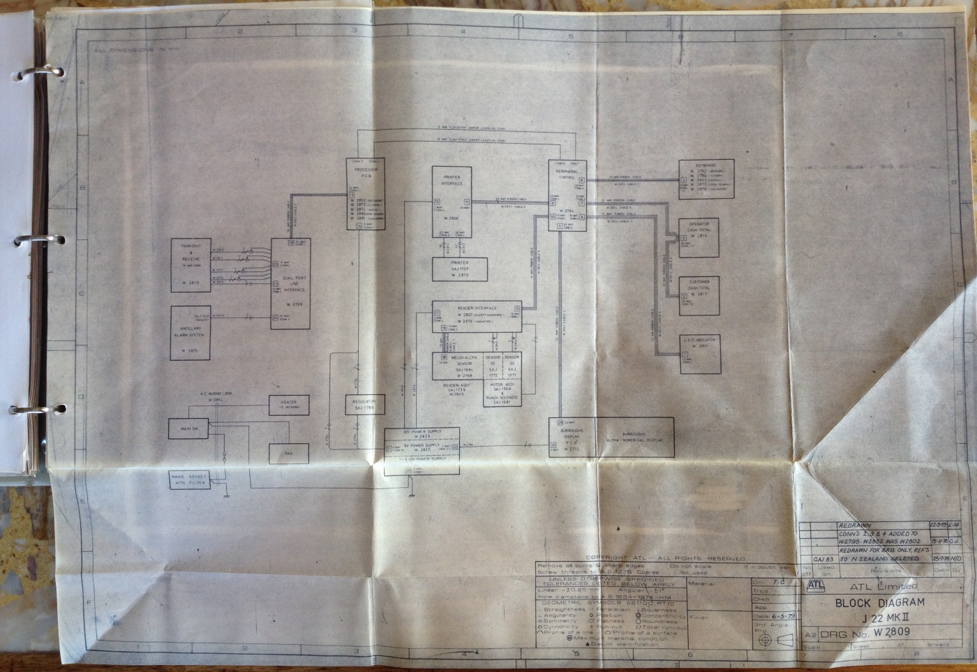
The Block Diagram above shows the outermost view of the TIM identifying its major functional units or modules. Inside the blocks in the diagram there are drawing numbers that identify the drawings that provide all the details of the module relating to the block. The block diagram shows the whole machine and how the blocks interconnect. The block shown at the top of the third column of blocks in the above image, is titled PROCESSOR PCB and identifies the following circuit diagram which provides the detail of this Printed Circuit Board, the subject of this block.
The PROCESSOR BOARD (PCB) is mentioned in the Table Of Contents page, section 3.4 Page 3/4, shown on top of the image above. This part of the manual contains a detailed description of the Processor Board with an accompanying circuit diagram as shown in the image below. This board, as with most boards of this vintage and later, is a PCB (Printed Circuit Board).
The J22 Processor Circuit Diagram drawing W2852
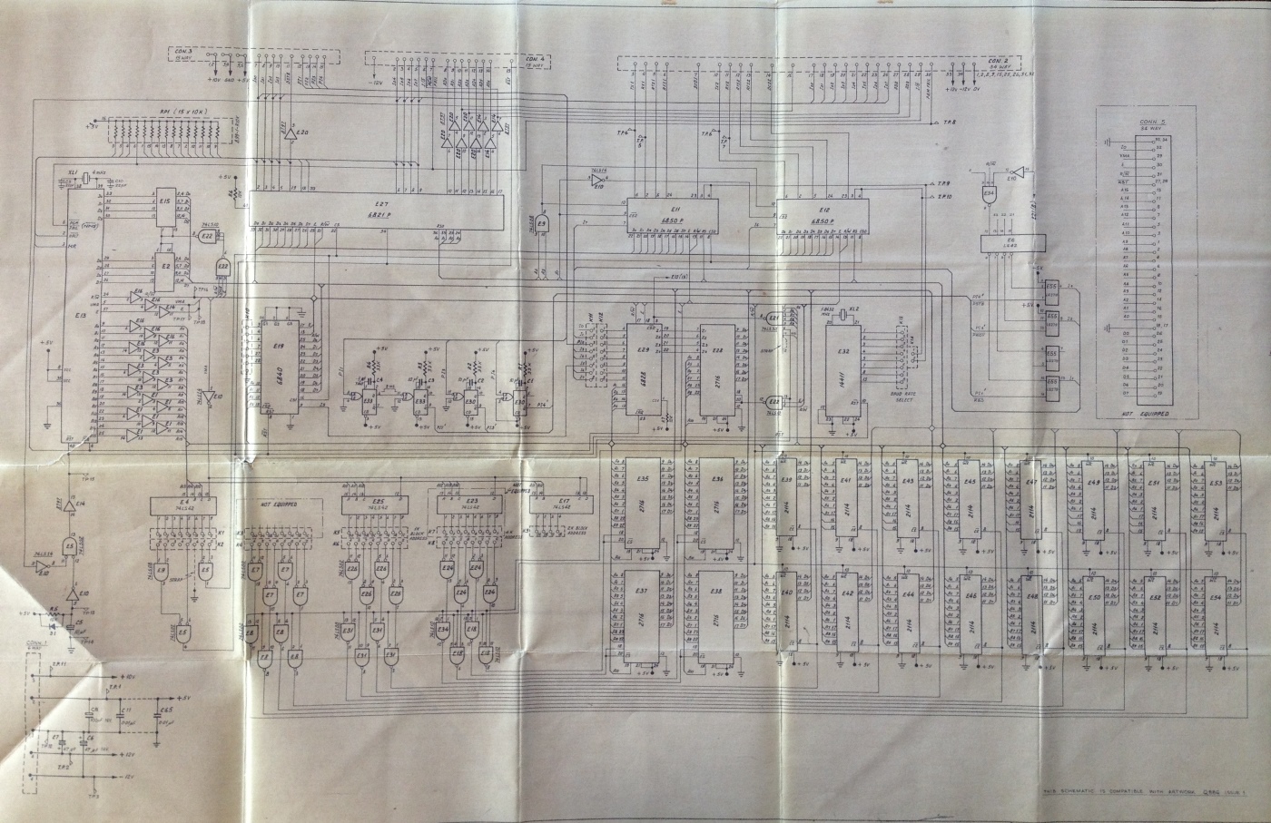
A larger rendition of the above Circuit Diagram image can be viewed in the Photo Gallery of this website, in the entry following the one for the image at the top of this page. The larger rendition makes it possible to read some of the text and the additional information provided with it keeps this page from becoming voluminous and boring to the not so technical reader. This larger rendition image also contains the complete detailed circuit description of this PCB from the manual, for the technical reader. To go to the photo gallery, click on the image at the top of this page.
The M6800 series microprocessor, which in the J22 is an M6802, can bee seen in the circuit diagram above as the tall, vertically oriented, rectangular component, on the far left of the diagram, above the horizontal crease which is almost half way up the page. The PCB that the above diagram defines can be seen in the image above titled Inside the J22 with covers removed. It is the large circuit board on the right hand side with the 7 EPROMs in a row with labels on them. If you look up the board from the right hand side of the right hand EPROM of those just mentioned, you will see a long black component on the right hand side, near the top of the board. This is the M6802 Microprocessor.
The creases in this diagram are a result of this page being part of the Technical Manual which has to be folded to fit in with the other A4 dimension pages in the manual. I am not going to delve into the Processor PCB in any detail here, as I have included a full technical description in another page of this website, as mentioned in the previous paragraph. I will provide some overview comments of my own here and I have also included the Keyboard PCB later in this page, as a simpler sample of a technical description of a circuit board. It is interesting to compare some of the ICs in the Processor PCB with contemporary counterparts, to see how much progress has taken place since the 1970s.
The circuit diagram above, despite the fact that it is part of a J22 MK II Technical Manual and that the drawing is labelled as being of a J22 MK II, is different to the actual Processor PCB in my J22. Possibly the circuit diagram is of a J22 MK II belonging to another project other than Brisbane, probably Sha Tin. One obvious difference is that the number of EPROMs in the diagram is five and the number actually on the PCB in my J22 is seven. As the Brisbane firmware in my J22 uses all seven EPROMs I conclude that the firmware storage capacity increased since the Circuit Diagram above was created resulting in the addition of two more EPROMs. In the above diagram there are two side by side columns of 3 ICs, both in the lower middle of the image. These ICs are represented as vertically oriented, medium sized, rectangles. All but the top left one are EPROMs with the type number 2716. There are only five of them in this drawing but they correlate to the seven EPROMs in the image above titled Inside the J22 with covers removed and are described in the second paragraph underneath that image. These 2716 type EPROMs have a storage capacity of 2KB each, confirming the addressing scheme on the labels, as discussed previously. To the right of these EPROMs in the Circuit Diagram above, are two rows of eight smaller rectangles, which represent a smaller IC with a type number 2114. This identifies them as a 1024 by 4 bit static RAMs (Random Access Memory). Static RAM refers to the fact that these RAMs do not require refresh circuitry like dynamic RAM does. It takes two of these 4 bit (or Nibble) ICs to implement 1KB of RAM as it takes two four bit nibbles to implement an eight bit byte. In other words, with the two rows of eight of these, we have 8KB of main memory. As previously mentioned, in the Brisbane version of the J22 MK II, as seen in the image above titled Inside the J22 with covers removed, there is increased maximum RAM capacity. To the right of the EPROMs in that image, which are the seven components with labels on them, there are two rows of twelve IC sockets. This provides for a maximum memory capacity of 12KB, using the 2114 RAMs, if all the sockets are filled with RAM ICs. In my J22, only four of the sockets are filled and in the image above titled Inside the J22 with covers removed, only the top part of two of these RAMs can be seen, installed in the IC sockets on the far right hand side of the two banks of IC sockets. With only four of the 2114 ICs installed this machine only has 2KB of main memory. Compare that with the PC I am currently editing this file on, with an unremarkable by 2015 standards, 4GB of main memory.
 Go back to the index
Go to the bottom of the page
Go back to the index
Go to the bottom of the page
The long horizontal oblong IC near the top left of the circuit diagram above, is the M6821, which is the PIA (Peripheral Interface Adapter). This is used to control a multitude of peripherals within the J22 terminal, like the printer and reader, via the Peripheral Interface PCB. The connectors that connect to short ribbon cables that provide the electrical connection between the PIA and the Peripheral Interface PCB, are shown as two narrow horizontal oblongs, with dashed outlines, at the very top left of the image above. These represent connectors three and four and the short ribbon cables, are clearly visible looking like archways between the Processor PCB on the right and the Peripheral Interface Board on the left, in the image above titled Inside the J22 with covers removed. These are visible to the left and up from the left hand end of the bank of EPROMs, the ICs on the Processor PCB with labels on them. The connectors are identified on the surface of the Processor PCB, shown in that image near the left edge of the board, with the words CONNECTOR 3 and CONNECTOR 4, in white vertically oriented writing. In that image, move up the line of connectors to the two grey cylindrical capacitors and then to the right to the first of the long ICs. This is the PIA.
The MC6850 ICs are called ACIAs (Asynchronous Communications Interface Adaptors). They provide the logic required to communicate on a serial communications line and interface the information from and to the line with the M6800 microprocessor. There are two of these in the Processor PCB circuit diagram above, side by side immediately to the right of the long horizontal PIA IC. In the image above titled Inside the J22 with covers removed there are three medium sized ICs visible at the upper right of the Processor PCB. The left hand two of these three are the two MC6850s. These ICs connect via their serial lines to the long line drivers that connect with the host totalisator computers.
In the lower left corner of the Processor Circuit Diagram above, there is a circuit which includes 27 components that look like eggs with one end removed leaving a flat end, that is facing up. This circuit, which includes the ICs in a row above the egg like symbols, is the Address Decoding Logic. The circuits represented by the egg like symbols are called And Gates. An AND Gate, has an active output if and only if all its inputs are active, otherwise its output remains inactive. Some of the inputs and outputs of these gates have small circles where the connection is made with the gate and these symbols identify inversion so the active state is represented by what usually is considered inactive. When an AND gate has the inversion symbol on its output it is called a NAND gate indicating Not AND. The ICs in a row above the NAND gates are 74LS42s which are BCD (Binary Coded Decimal) Decoder/Drivers. These set one of the outputs active, depending on which valid combination of inputs is being presented. The input is presented as Binary Coded Decimal. As the name Address Decoding Logic suggests, this circuit performs address decoding. As memory is implemented using multiple memory ICs the address decoding logic determines which of these ICs a particular address on the Address Bus is referring to. The low order Address Bits A0 to A9 connect directly to the RAM and PROM address lines as these address successive locations within a PROM IC or one of the RAM IC pairs, which in the case of PROMs are 2716s or RAMs are 2114s, as described previously. The higher order address bits, A10 to A15 are connected to the inputs of the 74LS42s of the address decoding logic which determines what address windows each of the eight pairs of RAM ICs fit into as well as the five EPROMs. The address decoding logic enables the required RAM ICs with an active low CE (Chip Enable) signal and EPROM ICs with a low CS (Chip Select) signal. Remember, the RAM ICs are addressed in pairs because it takes two nibble oriented ICs to implement a byte of memory.
The entry in the Table Of Contents page shown above the two images above, refers to the PERIPHERAL CONTROL BOARD section 3.5 page 3/16. I have not presented the circuit descriptions contained in this section however I have included the introductory paragraph below as a quick look at its functionality. The Peripheral Control Board can be seen in the image above titled Inside the J22 with covers removed. It is the circuit board on the left hand side with the ATL logo visible at the top.
Technical Manual Part 1 extract page 3/16
| 3.5 | PERIPHERAL CONTROL BOARD |
| |
| The Peripheral Control Board provides the interface between the Processor Board and the following peripherals. |
| |
- Reader Interface.
- Printer Interface.
- Keyboard.
- Operator/Cutomer Cash Total Displays.
- LED Indicator Display.
- Burroughs Display.
|
I have reproduced the whole of section 3.6, consisting of 3.6.1 to 3.6.6 as identified at the bottom of the TABLE OF CONTENTS extract shown above. I think this is particularly pertinent as the Keyboard is clearly visible in the image at the top of this page making correlation easy.
Note that section 3.6.6 titled Circuit Description only describes the electronics in the Keyboard PCB itself which contains all the Hall Effect keyswitches, it does not contain a description of the additional Keyboard functionality in the Peripheral Control Board covered in section 3.5.3. The following text relates to Figure 6 which is the Keyboard Schematic Diagram shown in the following image.
Also note the following description differs from my sample J22. The Manual describes four meeting keys and my machine only has three. My J22 is missing the PRO Provincial button. Obviously a modification has been performed but I will not guess at how this discrepancy eventuated.
KEYBOARD extract from Technical Manual
| 3.6 | KEYBOARD |
| | |
| | Refer to Figures 5 and 6 |
| | |
| | The keyboard consists of a matrix of 16 X 7 momentary-action Hall-effect keys, providing a maximum compliment of 112 keys. Only 65 of these keys are used, plus two spare keys, the remainder are blanked out by the escutcheon panel. |
| | |
| 3.6.1 | Meeting Keys |
| | |
| | The four black keys located on the left of the top row are used to select one of four meetings, as follows: |
| |
| BRI | Brisbane |
| SYD | Sydney |
| MEL | Melbourne |
| PRO | Provincial |
|
| | |
| 3.6.2 | Pool Keys |
| | |
| | The fourteen black keys located on the second and third rows are used to select the pool, as follows: |
| |
| TBL | Treble |
| QAD | Quadrella |
| WIN | Win |
| PLA | Place |
| W-P | Win-Place |
| QIN | Quinella |
| FCT | Forecast |
| FCT BOX | Forecast Box |
| DBL | Double |
| D-D | Daily Double |
| X-D | Extra Double |
| TRF | Trifecta |
| TRF BOX | Trifect Box |
| TRO | Trio |
|
| | |
| 3.6.3 | Value Keys |
| | |
| | The twelve black keys marked 1/2, 0 to 9, and a decimal point located on the right of the keyboard, are used to enter betting and cash total amounts. The 1 to 9 keys can also be used to enter a race number or a special function number. |
| | |
| 3.6.4 | Runner Number Keys |
| | |
| | The twenty-four red keys marked 1 to 24, located on the fifth and sixth rows, are used to enter the runner numbers. The three black control keys, F, BANK and /, are used in conjunction with the runner number keys, to select field bets, banker and leg separator; the latter is used to separate legs in all multi-race pools. When a Ticket Serial Number (TSN) is to be manually entered, the leg separator (/) and the 1 to 9 keys become hexadecimal digits 0 to 9 and the 10 to 15 keys become hexadecimal digits A to F. When a race number of 10, 11 or 12 is required, the runner number keys must be used. |
| | |
| 3.6.5 | Control Keys |
| | |
| | There are eleven black control keys, one on the first row, (Webmasters note: On my J22 shown at the top of the page, the Race key on the first row is Grey with black letters.) one on the sixth row and the remainder on the seventh row. The keys and their functions are as follows: |
| |
| RACE | Selected before a race number. Also used, in conjunction with the value keys, as a plus (+) sign in an adding machine mode. |
| F (Field) | Selects the entire field of runners in certain pools. |
| / (Leg Separator) | Used to separate the runner(s) selected in each leg of a multi-race pool. Also used to separate values in a Win-Place (each way) pool. |
| BANK | Selected following a runner number to indicate that the number is to be included in every bet of an all ways group. |
| FUNC | Used in conjunction with the 1 to 9 value keys to transmit special function messages to the host processor. |
| PAY | Used in conjunction with the hexadecimal keys to transmit a TSN to the host processor. Only used when the TSN cannot be read automatically. |
| BAD SALE | Used to cancel any ticket that cannot be sold. The ticket will normally be automatically read and cancelled. If the TSN cannot be automatically read, the hexadecimal keys are used to manually enter it. |
| TEST | Initiates a message to the host processor which then orders the printer to print a test ticket. The ticket may then be examined to ensure that the printing is legible and all data are correct. |
| CLEAR ENTRY | The first depression of this key clears the last value or runner number entry made, to permit an error to be corrected. The second depression of the key resets the terminal and displays the bet details. |
| CLEAR TOTAL | Used to clear the cash totals displayed at the end of each customer transaction. |
| TRANSMIT | Used to terminate a transaction and to transmit the data to the host processor. |
| NOTE: | Two spare keys are provided, one on the second row to provide an additional pool, and one on the fifth row to provide an additional control function. |
|
| | |
| 3.6.6 | Circuit Description |
| | |
| | The 16 X 7 matrix of keys is scanned in columns and rows under the control of clock pulses from the Peripheral Control Board. Two 8-channel data selectors, E2 and E3, are used to scan the columns and a third 8-channel data selector, E1, is used to scan the rows. |
| | The keyboard is scanned continuously for a key which has been pressed. During the first eight column scans a logic low is present on the COL 8 input and E3 is disabled via E4c; during the second eight column scans E3 is enabled. If, for example, the MEL pool key (column 3, row 1) is pressed, a logic low will be set at the X2 input of E2 and also at the X0 input of E1. When the clock pulses from the column counter are 0100 and the clock pulses from the row counter are 000, a logic low will be present at the Z outputs of E2 and E1. These are gated in E4d to produce a logic high which is used to stop the binary counter in the Peripheral Control Board; this signal is also used to feed an interrupt request to the MPU. The MPU then reads the data from the binary clock and interprets the function of the key from the relevant look-up table. When the key is released the scanning re-commences. |
The J22 Keyboard Schematic from the Technical Manual
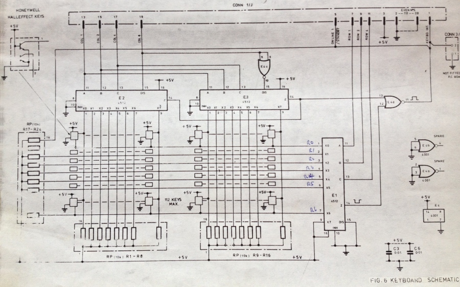
The Keyboard Schematic shown above, is referred to as Figure 6 in the text titled KEYBOARD extract from Technical Manual shown above the image above and is identified as such in the bottom right hand corner of that image. As can be seen from the image, everything about this history is fading! This diagram has been presented here as it is a relatively simple diagram and I wish to refrain from delving too deeply into the technical aspects of the machine here, as it will loose all the not so technical readers. To see an example of a more complex circuit diagram, have a look at the Processor PCB Circuit Diagram, which is a larger rendition of the image above titled The J22 Processor Circuit Diagram drawing W2852, in the Photo Gallery making it more legible. This larger rendition in the Photo Gallery is accompanied with the complete technical description of the circuit from the manual. To go to the photo gallery to see this larger image with the circuit description, click on the image at the top of the page, then click on the thumbnail of The J22 Processor PCB Circuit Diagram.
It is interesting to note the annotation on the drawing, which is visible on the image above, the likes of which, often appears on engineering drawings. An engineer or technician has labelled pins 1 through 7 of IC E1, R0 R1 R2 R3 R4 R5 R6. Engineering staff often write on drawings as a memory jogger or to expedite reading the diagram by not having to reference another document. R0 to R6 do not refer to resistors but identify these lines as the row lines of the keyboard matrix. This seems fairly evident and I am surprised it required annotating, unless I have missed the point!
This drawing is of additional interest, as it demonstrates a method of simplifying circuit diagrams. It has a dashed line box in the top left hand corner titled Honeywell Hall Effect keys. It shows the symbols for two transistors in it connected in a circuit. Electrically this is what the Hall Effect Keys look like, which are activated by the operator hitting keys on the keyboard. There is one of these for every key on the keyboard. These keys on the keyboard are represented in the matrix below the ICs (Integrated Circuits) labeled E2 and E3 in the drawing. This matrix is drawn as two banks of 8 vertical lines and 7 horizontal lines giving a total of 112 points where these lines cross. At each of these points is a Hall Effect Key connected to the associated vertical line and the associated horizontal line. The Hall Effect keys are identified in the drawing in different ways, each change saves more space and leaves more implied. First an empty box at each corner of the two 8 X 7 matrices with connections to their associated horizontal and vertical lines. The Hall Effect Key drawing mentioned, has an arrow pointing to the top left box of the matrix below E2. This implies that every similar corner box in this and the matrix below E3 contain the shown circuit. Second are disconnected rectangles, that can be seen arranged in 4 columns of five empty boxes between the upper and lower corner boxes, which show their connections to their lines. It is implied that every empty disconnected box has the same connections to their associated horizontal and vertical lines just like the boxes at the top and bottom of their rows and consequently that they contain the same circuit of the Hall Effect Key. Finally, oriented horizontally between the five empty disconnected boxes at the left and right hand sides of the two matrices, are horizontal rows consisting of 9 dashes. These dashes imply a repetition of the left or right column boxes of the two 8 X 7 matrices, at each of the intervening 6 columns between the outer columns that the rectangles and squares are attached to. This further indicates that these additional columns of implied boxes have a connection to their associated vertical and horizontal lines, as well as having the Hall Effect Circuit inside them. The diagram would be significantly larger if all these implied circuits were shown in detail.
In summary of the circuit description above this image, for the not so technical reader, the support electronics in this drawing, in conjunction with other interface electronics, checks every key on the keyboard in sequence to see if it is being pressed.
TABLE OF CONTENTS (cont'd)
| SECTION 3 | | PAGE |
|---|
| | | |
| 3.7 | CASH TOTAL DISPLAYS | 3/27 |
| 3.7.1 | Operator Cash Total Display | 3/27 |
| 3.7.2 | Customer Cash Total Display | 3/28 |
| | | |
| 3.8 | LED INDICATOR DISPLAY | 3/28 |
| | | |
| 3.9 | BURROUGHS DISPLAY | 3/29 |
| | | |
| 3.10 | PRINTER INTERFACE BOARD | 3/30 |
| 3.10.1 | Hammer Drive | 3/30 |
| 3.10.2 | Guillotine Solenoid
and Ribbon Drives | 3/31 |
| 3.10.3 | Printer Motor Control | 3/32 |
| 3.10.4 | Microswitch Interface | 3/35 |
| 3.10.5 | Power Supply | 3/36 |
| | | |
| 3.11 | PRINTER ASSEMBLY | 3/36 |
| 3.11.1 | Drive Motor Assembly | 3/36 |
| 3.11.2 | Matrix Print Head Assembly | 3/37 |
| 3.11.3 | Guillotine Assembly | 3/38 |
| 3.11.4 | Ribbon Motor Assemblies | 3/38 |
| | | |
| 3.12 | READER INTERFACE BOARD | 3/38 |
| 3.12.1 | Welch Allyn Assembly | 3/38 |
| 3.12.2 | Welch Allyn Amplifier | 3/39 |
| 3.12.3 | Reader Motor Control | 3/40 |
| 3.12.4 | Power Supply | 3/43 |
| | | |
| 3.13 | READER ASSEMBLY | 3/44 |
| 3.13.1 | Drive Motor Assembly | 3/44 |
| 3.13.2 | Welch Allyn
Read Head Assembly | 3/45 |
| 3.13.3 | Welch Allyn Amplifier | 3/45 |
| | | |
| | | iv |
The following is a short paragraph extract introducing The CASH TOTAL DISPLAYS mentioned in the Table Of Contents above. The Cash Total Display for the operator mentioned in the following text, can be seen in the image at the top of this page, to the right of the Burroughs Display, which is the long horizontal display in the black operators display panel. The Cash Total Display for the customer, is the same type as the operator's Cash Total Display and is seen as a dark rectangle, parallel to the back of the machine, in the rear left part of it, on the lid, behind the ticket printer exit chute.
Technical Manual Part 1 extract page 3/27
| 3.7 | CASH TOTAL DISPLAYS |
| | |
| | The Cash Total Displays each comprise and 8-digit LED display which indicates the amount of cash payable by, or to, the operator at the end of a transaction. One display is fitted on the operator's side of the terminal and the other on the customer's side of the terminal. |
Following is an extract from the manual as identified in the Table Of Contents page above titled LED INDICATOR DISPLAY section 3.8 starting page 3/28. I have included this, as it describes the LEDS in the annunciator panel, which is clearly visible in the J22 image at the top of this page. It is on top of the Burroughs Display which is the long thin text information display on the left of the black operator display panel. I have not included Figure 9, as I have already included sufficient information on circuit diagrams, which as this manual's bulk consists of this, could make this web page boring for the non technical readers. I have included the short paragraph at the beginning of this segment, as it connects the title to the LED descriptions and it is short.
Technical Manual Part 1 extract page 3/28
| 3.8 | LED INDICATOR DISPLAY |
| | |
| | Refer to Figure 9. |
| | |
| | The LED Indicator Display consists of nine LEDs, LED1 TO LED7, LED9 and LED10. LED1 to LED7 are addressed by the A2 signal from the Peripheral Control Board and the individual LED driven by the cathode signals, K1 to K7. LED9 and LED10 are addressed by the A1 signal and driven by the K1 and K2 cathode signals. The LEDs and their functions are as follows: |
| |
LED1 (Yellow)
- POWER ON | Indicates that the mains supply is switched on |
LED2 and LED3 (Red)
- POLL1 POLL2 | These indicators flash to indicate that the terminal is on-line to the host computer. The terminal will operate when only one indicator flashes but will not operate if both are off. |
LED4 (Green)
- SELL | Indicates that the terminal can be used for sell transactions |
LED5 (Green)
- PAY | Indicates that the terminal can be used for pay transactions |
LED6 (Red)
- 30 V FAIL | Indicates a failure of the +30 V Power Supply |
LED7 (Red)
- FAULT | Indicates an internal fault |
LED9 (Red)
- PAPER OUT | Indicates that the ticket roll is exhausted. No TIM operations may be performed until a new roll is inserted. |
LED10 (Red)
- REJECT | Indicates that the last bet transaction has been rejected by the host processor. The reason for the rejection is shown on the Burroughs Display. |
|
Following is a not so technical extract from the Technical Manual, relating to the BURROUGHS DISPLAY from Section 3.9 Page 3/29 as appears in the Table Of Contents above. I have not provided Figure 10.
Technical Manual Part 1 extract page 3/29
| 3.9 | BURROUGHS DISPLAY |
| | |
| | Refer to Figure 10. |
| | |
| | The Burroughs Display consists of a self-scan display module with 32 alpha-numeric characters, formatted in a 5 X 7 dot matrix. It displays: |
| |
- The betting information as it is keyed in, which can be cleared by either two depressions of the CLEAR ENTRY key or a response from the host processor.
- The amount of dividend of the last ticket read or keyed in.
- Special messages from the MPU, or the host processor.
|
| | This display which is a discrete assembly forming an integral part of the terminal, is connected to the J22 Mark II TIM via a terminal printed circuit board (refer to figure 10) and interconnecting cables. In addition to the data, the cables carry the +5 V, -12 V and +250 V power supplies to the display. |
The PRINTER INTERFACE BOARD and PRINTER ASSEMBLY mentioned above in the Table Of Contents, in sections 3.10 and 3.11 relates to the printer which uses hammers to transfer ink from a ribbon onto the ticket. An example of a ticket produced by this printer can be seen in the small yellow image above, near the top, titled A ticket printed on a J22 Terminal. The exit chute for the printer is clearly visible on the shiny lid of the J22 in the image at the top of this page, about half way between the front and back of the lid and towards left hand side. In one of the images above, titled Inside the J22 with covers removed, the Printer Assembly can be seen in the top left corner. This whole metallic assembly, extending from the left hand side of the machine to near the middle, is the printer. In the same image, the near printer side plate, can be seen reaching towards an apex, which is just off the top of the image. At the apex is the ticket exit chute, which was previously mentioned. In that same image, the four yellow rectangles in a row on the side of the printer belong to four of the solenoids that drive four of the print hammers. Ticket roll holders were installed below each of the sellers bench tops, near the ticket paper entry chute, in the bottom of the machine. The paper entry chute on the J22 is directly below the exit chute on the top. In the first side elevation drawing of the printer, in the top row on the left hand side of the image below, the exit chute is labelled PAPER EXIT, which is the uppermost text in this side elevation. Conversely, the entry chute in the same side elevation, is labelled PAPER IN FEED, which is the lowest text in this side elevation. To thread a new roll of paper in the machine, required feeding the paper into the entry chute with one hand, whilst engaging the printer paper advance motor, with the other hand on the keyboard, or by manually rotating the paper feed knob on the side of the printer. To rotate the paper feed knob requires the lid of the J22 to be removed to gain access to the knob, which is on the side of the printer. The paper feed knob can be seen in the previously mentioned side elevation printer drawing below. It is the large circle consisting of two close together concentric rings representing the grip part of the knob, surrounding a smaller concentric ring which is the spindle of the knob, located centrally in the side plate. There is a cross drawn through the centre of the knob.
The J22 Printer Assembly drawing
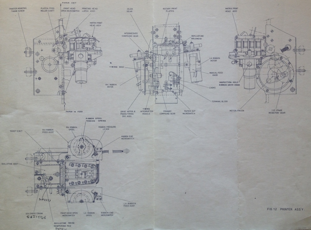
This image is extracted from the section indicated in the Table of Contents page above, section 3.11 titled PRINTER ASSEMBLY on page 3/36 and is labelled Fig 12 PRINTER ASS'Y as seen in the bottom right hand corner of the image. It is a good example of a mechanical Engineering Drawing.
I have included a short description of the PRINTER INTERFACE BOARD from section 3.10 as indicated in the Table of Contents above. It omits all the in depth circuit descriptions, consequently I have also omitted Figure 11.
Technical Manual Part 1 extract page 3/30
| 3.10 | PRINTER INTERFACE BOARD |
| | |
| | Refer to Figure 11. |
| | |
| | This board provides the buffered drives for the matrix printer hammers, guillotine solenoid, ribbon motors and printer drive motor. The control logic levels are produced by the Peripheral Control Board under the control of the Processor Board. |
The guillotine solenoid mentioned in the extract above, can be seen in the image above, of the Printer Assembly drawing, in the end elevation in the middle of the top three elevations, with the label GUILLOTINE SOLENOID on the right hand side, near the top. The ribbon motors, also mentioned in the extract, can be seen in this same end elevation with the labels RH RIBBON MOTOR and LH RIBBON MOTOR.
Following is the introduction to the Printer Motor Control as referred to in the Table of Contents above in section 3.10.3.
Technical Manual Part 1 extract page 3/32
| 3.10.3 | Printer Motor Control |
| | |
| | The printer motor is driven at a preset, regulated speed when a motor drive signal is received from the Peripheral Control board. A precision, closed loop, speed control circuit provides the regulation. |
I have also included the introduction to the Drive Motor Assembly, as referred to in the Table of Contents above in section 3.11.1. This drive motor is visible in the image above titled The J22 Printer Assembly drawing in the middle view on the top row of the image, labelled DRIVE MOTOR & PINION/TIMING DISC ASSY, the far left bottom label of that view. In the same view the print platen, mentioned below, is visible labelled ROTARY PRINT PLATEN, at the top of the view. In the same image, in the left hand end elevation, in the first view on the top row, another print roller item is labelled PLATEN FEED ROLLER SHAFT, the second label in the top row of labels. This is the shaft that the Rotary Print Platen rotates on.
Technical Manual Part 1 extract page 3/36
| 3.11.1 | Drive Motor Assembly |
| | |
| | This assembly consists of a printed circuit motor which drives a rotary print platen via a reduction gear train. The speed of the motor is controlled by a present speed control circuit in the Printer Interface Board (refer to subsection 3.10). An interrupter module produces strobe pulses; whose frequency is relative to speed, and feeds them to the speed control circuit. As the rotary print platen is rotated, by the drive motor and reduction gear train, a knurled portion on its surface grips and feeds the ticket paper past the print head assembly. A manual feed knob connected to the reduction gear train enables the platen to be manually rotated; this is used to initially feed paper past the print head assembly. A paper out micro-switch on the paper feed senses the absence of paper and feeds a signal via the Ancillary Alarm System and the Dual-Port Line Interface to the Processor Board. |
The Matrix Print Head Assembly, follows the above entry as referred to in the Table of Contents above in section 3.11.2.
Technical Manual Part 1 extract page 3/37
| 3.11.2 | Matrix Print Head Assembly |
| | |
| | This assembly consists of three 5X7 dot matrix print hammers and two bar code print hammers. Banks 1 and 3 (refer to figure 13) each consist of seven large hammers and a bar code hammer controlled by solenoids which are driven by the Printer Interface Board. Bank 2 consists of seven small hammers which are also solenoid controlled. The print head assembly prints at a speed of 30 large characters a second and 60 small characters a second. |
| | The assembly is hinged to permit access to the ribbon; when raised to the operating position the assembly is retained by a latch assembly. A print head open micro-switch senses when the assembly is open and feeds a signal via the Printer Interface Board and the Peripheral Control Board to the Processor Board. |
The latch assembly mentioned above, can be seen in the above image, in the first view on the top row, labelled PRINTING HEAD LATCH ASSY, the right hand label in the top row of labels. The Print Head Open Micro-Switch mentioned above can also be seen in the above image, in the plan view at the bottom, labelled PRINT HEAD OPEN MICROSWITCH in the third label at the bottom.
Again, the Guillotine Assembly follows the above entry as referred to in the Table of Contents above in section 3.11.3. The Guillotine is visible in the image above titled The J22 Printer Assembly drawing, in the plan view at the bottom, labelled GUILLOTINE ASSY, the far left label.
Technical Manual Part 1 extract page 3/38
| 3.11.3 | Guillotine Assembly |
| | |
| | The guillotine is a rotary-operated, self-sharpening type. When its controlling solenoid is operated, by the Printer Interface Board, the solenoid spindle rotates and causes the crank to move the guillotine forward to cut the ticket to length. |
I am just continuing here with the manual as it is not delving more deeply into the circuitry at this stage. Continuing with the ticket printer, we come to the Ribbon Motor Assemblies, as referred to in the Table of Contents above in section 3.11.4. Parts of the ribbon assemblies are visible in the image above titled The J22 Printer Assembly drawing in the plan view at the bottom with labels RH RIBBON FEED ASSY and LH RIBBON FEED ASSY the right and left Ribbon Feed Assemblies. Items identified in these assemblies, are the right and left Ribbon Spools, a Ribbon Spool Tension Spring, the Ribbon Pressure Lever and the left and right Ribbon End Microswitches. In the same image, looking at the end elevation in the top row middle view, the right and left Ribbon Motors are visible labelled RH RIBBON MOTOR and LH RIBBON MOTOR.
Technical Manual Part 1 extract page 3/38
| 3.11.4 | Ribbon Motor Assemblies |
| | |
| | Two ribbon motors are provided, one to drive the ribbon forward and the other to drive the ribbon reverse. The direction in which it is to be driven depends upon the operation of either of two ribbon end microswicthes. For example, if the reverse ribbon end microswitch was the last one operated, the forward ribbon motor is driven until its ribbon end microswitch operates; then the reverse motor is driven. |
The Welch Allyn reader, mentioned above in the Table Of Contents, in sections 3.12 and 3.13, was a major feature of the J22. As mentioned previously, the system in Brisbane where the J22 had its debut, was the first sell pay system for Automatic Totalisators. This was the first instance of an Automatic Totalisators TIM being capable of retrieving the bet details from a barcode, printed on the ticket by the same machine. The tickets being read are the ones produced by the printers the same as the one described above. This reader's intake chute is clearly visible in the J22 image at the top of this page. It is on top of the rectangular vertically oriented silver ticket slide on the right hand side of the keyboard. A ticket proximity sensor signals that a ticket has been pushed into the entry chute and the ticket transport motor is started to move the ticket through the reader transport, passing the bar code sensors for reading and then ejecting the ticket at the ticket exit chute visible in the image above the ticket entry chute. This reader can be seen on the right hand side, at the top of the image above titled Inside the J22 with covers removed.
Following is the introduction to section 3.12 of the Technical Manual.
Technical Manual Part 1 extract page 3/38
| 3.12 | READER INTERFACE BOARD |
| | |
| | Refer to Figures 15 and 16 |
| | |
| | The purpose of this board is to sense the insertion of a ticket, to read the upper and lower bar codes and to provide the reader motor speed regulation. Provision is also made to control a ticket punch solenoid. |
The next extract, section 3.12.1 as shown in the Table of Contents above, titled Welch Allyn Assembly follows the one above and is the last from this part of the manual I will present. The reason is that following this entry, this section of the manual delves much further into more technical circuit descriptions and this will lose all readers bar those who are interested in electronics engineering and technology history. This segment starts to become technical however it only describes the most simple of circuits, a lamp and two photo transistors, so I have decided to present it. I have not provided figures 15 or 16 mentioned above, as they provide information that is not particularly interesting like wiring and pin connections.
Technical Manual Part 1 extract page 3/38
| 3.12.1 | Welch Allyn Assembly |
| | |
| | The Welch Allyn Assembly is an integral unit which consists of a lamp and two photo-transistors, Q1 and Q2. The lamp is used to illuminate both edges of the ticket via two fibre-optic cables. When a bar code passes beneath the cables, the lack of reflected light causes Q1 and Q2 to produce a pulse. The outputs of Q1 and Q2 are fed via Connector 1, Pins 6 and 8, to an operational amplifier stage in the Welch Allyn Amplifier. |
TABLE OF CONTENTS (cont'd)
| SECTION 3 | | PAGE |
|---|
| | | |
| 3.14 | DUAL-PORT LINE INTERFACE | 3/45 |
| 3.14.1 | Internal Transmit and Receive Wiring | 3/46 |
| 3.14.2 | Terminal Address Interface | 3/46 |
| 3.14.3 | Ancillary Alarm Interface | 3/46 |
| 3.14.4 | Dual Line Driver | 3/47 |
| 3.14.5 | Dual Line Receiver | 3/47 |
| 3.14.6 | Data Carrier Detect Circuit | 3/47 |
| 3.14.7 | Power Supply | 3/48 |
| | | |
| 3.15 | ANCILLARY ALARM SYSTEM | 3/48 |
| 3.15.1 | Paper Low Microswitch | 3/49 |
| 3.15.2 | Bandit Alarm Pushbutton | 3/49 |
| 3.15.3 | Key Switch Assembly | 3/49 |
| 3.15.4 | Toggle Switch | 3/50 |
| | | |
| 3.16 | POWER SUPPLY ASSEMBLY | 3/50 |
| 3.16.1 | 30 V Power Supply | 3/50 |
| 3.16.2 | 5 V Power Supply | 3/53 |
| | | |
| SECTION 4 | MAINTENANCE | 3/50 |
| | | |
| 4.1 | PREVENTATIVE MAINTENANCE | 4/1 |
| 4.1.1 | Daily Preventative Maintenance | 4/2 |
| 4.1.2 | Weekly Preventative Maintenance | 4/3 |
| 4.1.3 | Ribbon Replacement and Motor
Reversal Check | 4/4 |
| | | |
| 4.2 | SELF TEST | 4/5 |
| 4.2.1 | Initialisation of Self Test | 4/6 |
| 4.2.2 | Printer Test | 4/6 |
| 4.2.3 | Reader Test | 4/6 |
| | | |
| | | v |
Following is an extract from the manual titled DUAL-PORT LINE INTERFACE as shown in the Table of Contents page above section 3.14 Page 3/45. I have not provided Figures 19 and 20 as I have not provided information that depends on them.
Technical Manual Part 1 extract page 3/45
| 3.14 | DUAL-PORT LINE INTERFACE |
| | |
| | Refer to Figures 19 and 20 |
| | |
| | The purpose of this circuit is to provide two communication ports, each being serial asynchronous, multi-dropped and full duplex operating for communications between the Processor Board and the host processor. Each J22 Mark II TIM has a unique terminal address which is coded by means of the communications plug Connector 2. |
This is an extract, following the previous one in the manual, as indicated in the Table of Contents above section 3.14.1.
Technical Manual Part 1 extract page 3/46
| 3.14.1 | Internal Transmit and Receive Wiring |
| | |
| | The transmitter and receiver pairs from Connector 4 on the Dual-Port Line Interface and the terminal address lines from Connector 2 are wired to a 16-way connector for connection to the modem. |
We did not use modems in the Brisbane project for communication between the J22s distributed around the racetracks and the host totalisator computers. We used tri-state differential long line drivers to span the distance.
The Printer Test mentioned in the Table of Contents above in section 4.2.2 on page 4/6, is implemented by the M6800 code in the example under the heading Sample of the J22 M6800 Source Code near the top of this page. Following is the related section in the manual followed by the reader test section 4.2 on the same page. It is preceded in the manual by section 4.2.1, which I have not reproduced here. This section, titled Initialisation of Self Test, essentially enters self test mode. This is required, prior to performing the sequence of Self Tests, shown in the Table of Contents sections 4.2.2 and 4.2.3 above and sections 4.2.4 through 4.2.7, in the next Table of Contents below. I have summarised the process here as it is brief and relates to images on this page, which are not in the manual.
My summary of entering Self Test Mode: As can be seen in the image at the top of this page, the lid of the J22, the large shiny metal section at the top of the image, has a key-lock at the middle of the front section. To enter Self Test mode, the key is used to unlock and remove the lid. The Self Test Switch is then turned on. This switch, has a minute part showing in the above image titled Inside a J22 with covers removed. By following the horizontal line of the top of the black operator display panel, above the row of LEDs (lights), where the thin horizontal line of the edge of a circuit board can be seen, to the left edge of the image, where there is a small rectangular gap below the top of the operator display panel. Within this gap, the extreme right hand side of the Test Switch's silvery securing nut can be seen. Above the gap, slightly above the top of the display panel, the extreme right hand side of a blue label can be seen, with the letter F, which is the last letter of the word SELF on the label. It is hard to see but the horizontal bar of the L is also visible. When this switch is in the active position and the power is reset, Self Test Mode is active and the Burroughs Display confirms this state by displaying the words SELF TEST. The following Self Test examples from the manual can now be performed.
Technical Manual Part 1 extract page 4/6
| 4.2.2 | Printer Test |
| | |
|
- Press the FUNC key.
- Press the 2 runner key.
- Press the TRANSMIT key and, after a short pause, press the CLEAR ENTRY key.
- Remove and retain the self test tickets.
|
| | |
| 4.2.3 | Reader Test |
| | |
|
- Insert one of the self test tickets (produced during the preceding printer test) into the reader and check that it is transported through the reader. Remove the ticket.
- Check that the Burroughs Display reads: BAR=L26+R24 or (L24+R26) = 171717171717
|
| | Notes: |
|
- If the total number of bar codes is correct the L number and R number will show this and the TSN code will change (the last 12 digits are the TSN).
- If double bars are detected, then the plus sign will change to a D.
|
The SELF TEST section 4.2 of the manual as sampled above, continues in the following Table of Contents page and leads on to the FAULT FINDING section 4.3. The idea is that if any of the Self Tests fail, then the following Fault Finding section will provide a method for locating the source of the problem. The fault finding procedures in the technical manual, will provide instructions that will resolve a problem to a module and will restore operation if the module is replaced. In the field, on racetracks, the race-club technical staff, would often repair to this level and return the faulty module to ATL for repair. At ATL, hardware specialist technical staff, like myself, would repair the module to component level. This technical manual provides all the circuit diagrams and mechanical engineering drawings to achieve this. The main other source of information to achieve electronic component level repair, was the Data Books, provided by the manufacturers of Integrated Circuits. These Data Books detailed the functionality of the specific circuitry inside the ICs covered in the book. There usually were multiple books to cover all the ICs produced by a specific manufacturer. The books were categorised on the basis of the type of circuitry, the highest level example of this is Digital and Analogue. All this information sufficed to repair almost all of the problems. Every now and then you would come across a particularly elusive fault and you might have to resort to writing some fault specific M6800 diagnostic routine, to produce specific electronic signals suitable for synchronising a CRO scan to, so that the CRO trace can be analysed and the trail of fault effects can be followed to the cause which will identify the faulty component.
TABLE OF CONTENTS (cont'd)
| SECTION 4 | | PAGE |
|---|
| | | |
| 4.2.4 | Burroughs and Cash Total
Displays Test | 4/7 |
| 4.2.5 | LED Indicator Display Test | 4/8 |
| 4.2.6 | Communications Line Test | 4/8 |
| 4.2.7 | Microswitch Tests | 4/9 |
| | | |
| 4.3 | FAULT FINDING | 4/9 |
| | | |
| 4.4 | ALIGNMENT PROCEDURES | 4/10 |
| 4.4.1 | 30 V Power Supply | 4/10 |
| 4.4.2 | 250 V Power Supply | 4/11 |
| 4.4.3 | Peripheral Interface Board | 4/11 |
| 4.4.4 | Printer Interface Board | 4/12 |
| 4.4.5 | Reader Interface Board | 4/13 |
| | | |
| 4.5 | MECHANICAL ADJUSTMENTS | 4/15 |
| 4.5.1 | Keyboard Adjustment | 4/15 |
| 4.5.2 | Guillotine Crank Radial
Adjustment | 4/16 |
| 4.5.3 | Guillotine Pressure Ring
Adjustment | 4/16 |
| 4.5.4 | Print Head Microswitch
Adjustment | 4/17 |
| 4.5.5 | Paper Feed Adjustment | 4/17 |
| 4.5.6 | Print Head Adjustment | 4/18 |
| 4.5.7 | Print Head Side Float
Adjustment | 4/19 |
| 4.5.8 | Ribbon Motor Reversal
Microswitch Adjustment | 4/19 |
| 4.5.9 | Paper Out Microswitch Adjustment | 4/20 |
| | | |
| | | vi |
Following is section 4.2.4 as shown in the Table of Contents page above, titled Burroughs and Cash Total Displays Test on page 4/7. The Burroughs display and Cash Total displays can be seen on the image at the top of this page. The Burroughs display is the long alphanumeric display on the left hand side of the black operator display panel above the keyboard immediately to the right of the star that someone stuck to the machine. The display to the right of this is the Operator Cash Total display. At the top left side of the shiny lid of the J22, you can see the rectangular outline of the perspex cover of the Customer Cash Total Display, which is above and at right angles to, the printer's Ticket Exit chute. The Ticket Exit chute can be seen in the above image titled The J22 Printer Assembly drawing in the plan view at the bottom left titled TICKET EXIT and can also be seen in the left end elevation at the top left titled PAPER EXIT.
Technical Manual Part 1 extract page 4/7
| 4.2.4 | Burroughs and Cash Total Displays Test |
| | |
|
- Press the FUNC key.
- Press the 3 runner key.
- Press the TRANSMIT key.
- Check that the ASCII (upper case) character code is sequentially displayed on the Burroughs Display from @ through to ?.
- Check that both Cash Total Displays are incremented sequentially (all zeros through all nines and then all blanks) at approximately one-half second intervals.
- Check that the PAY and RECEIVE LED indicators on both Cash Total Displays are illuminated.
|
Another subject covered in the Technical Manual is the Troubleshooting Guide. This consists of lists of instructions relating to actions to be taken in the event of particular fault symptoms occurring, and includes Fault Finding Tables and Flow Charts that guide you through the troubleshooting processes. These are contained in section 4.3 FAULT FINDING, starting on page 4/9 as shown in the above table of contents page vi above.
Two examples of the Alignment Procedures under the heading ALIGNMENT PROCEDURES section 4.4 on page 4/10 in the above Table of Contents follow. They are identified in the above table as section 4.4.3, titled Peripheral Interface Board on page 4/11 and as section 4.4.4, titled Printer Interface Board on page 4/12.
This section of the manual covers several alignment procedures pertaining to several modules within the machine all of which are identified in the J22 Block Diagram shown above titled The J22 Block Diagram from the Technical Manual. These alignments are performed after the replacement of a module or when a malfunction has developed, that can be rectified by an alignment being performed. These often involve servo systems however they can be purely electronic or purely mechanical. A simplistic definition of a servo system is an electronically controlled mechanical device. The examples I have provided, show an extract relating to servo systems for the printer.
As I recall the Walther Print Head in the J22 printer, was a significant factor in the machines ability to print tickets quickly. It was a selling feature, that the J22 could have the ticket available for the customer within two seconds from hitting the Transmit key, which includes the host computer interaction as well. Test Points are mentioned in the alignment procedure below. These are metal posts that extend significant parts of the printed circuit above the surface of the circuit board, to make an easy connection point for test equipment like a Multimeter test lead or a CRO probe. CRO is a mnemonic for Cathode Ray Oscilloscope referred to in the following extract as Oscilloscope.When analysing faults, you invariably end up in parts of the circuit for which there are no test points and consequently have to fiddle to connect the test equipment to pins on ICs or legs of other components. A simple device called an IC test clip, is a spring loaded device that clips over the top of an IC making connection with the legs electrically extending them to exposed pins at the top of the clip, which are easy to attach test equipment to. RVs mentioned in the following procedures are Variable Resistors often used for adjusting electronic signals.
The first entry in this section is Refer to Figure 4. which is the Peripheral Control Board Circuit Diagram which I have not provided here. Note that in the following alignment procedure the FUNC (FUNCtion) key is used to initiate a test cycle. The FUNC key is described in section 3.6.5 above under the title KEYBOARD extract from Technical Manual sub heading 3.6.5 Control Keys .
Technical Manual Part 1 extract page 4/11
| 4.4.3 Peripheral Interface Board |
| |
| Refer to Figure 4. |
| |
- Initialise the self test, refer to sub-section 4.2.1.
- Connect an oscilloscope to test point TP3 on the Peripheral Control Board.
- Press the FUNC key, the 2 Runner key and then the TRANSMIT key to start the print cycle.
- Adjust RV2 to give a print hammer timing of 1 ms on Bank 1.
- Press the CLEAR ENTRY key to stop the print cycle, and remove the printed tickets.
- Connect the oscilloscope to test point TP6.
- Repeat step (c).
- Adjust RV3 to give a print hammer timing of 460 µs on Bank 2.
- Repeat step (e).
- Connect the oscilloscope to test point TP7.
- Repeat step (c).
- Adjust RV5 to give a print hammer timing of 1 ms on Bank 3.
- Repeat step (e)
- Connect the oscilloscope to test point TP8.
- Repeat step (c).
- Adjust RV4 to give a print guillotine timing of 30 ms.
- Repeat step (e) and remove the oscilloscope.
|
| NOTE: Potentiometer RV1 is used to adjust the volume of the Sonalert, BZ1. |
RV2 RV3 RV4 and RV5 on the Peripheral Interface Board, mentioned in the above procedure, are variable resistors or Potentiometers (depends on connection) and can be seen in the above image titled Inside a J22 with covers removed. On the far left hand side of the image, on the left hand edge of the Peripheral Interface Board, near the bottom of the image, are four rectangular components which are RV2 RV3 RV4 and RV5. The top two RV2 and RV3 are grey, the next RV4 is blue followed by RV5 another grey one.
Sonalert mentioned in the note at the end of the above alignment procedure, is a name derived from the words sonic and alert, which is a device that just generates an alarm tone. It is usually used to draw the operator's attention to an exception condition or fault that is being visually elucidated.
The next extract follows the previous section and commences on page 4/12 in section 4.4.4 titled Printer Interface Board. The first entry in this section is Refer to Figure 11. which is the Printer Interface Board Circuit Diagram, which I have not reproduced here.
Technical Manual Part 1 extract page 4/12
| 4.4.4 Printer Interface Board |
| |
| Refer to Figure 11. |
| |
- Initialise the self test, refer to sub-section 4.2.1.
- Connect an oscilloscope to test point TP3 on the Printer Interface Board.
- Press the FUNC key, the 2 Runner key and then the TRANSMIT key to start the printer motor.
- Adjust RV2 for a printer strobe (PSTB) pulse period of 2.8 ms (printer motor speed).
- Press the CLEAR ENTRY key to stop the printer motor, and remove the printed tickets.
- Connect the oscilloscope to test point TP6.
- Repeat step (c).
- Adjust RV1 for a printer motor stop pulse period of approximately 24 ms, depending on the tightness of the gearing.
- Repeat step (e) and remove the oscilloscope.
|
Technical Manual Part 2
Below, is the Table Of Contents for the Brisbane Technical Manual EM 288 Part 2 which relates to the ATL J22 TIM. As previously mentioned, Part 2 of the Technical Manual contains all the drawings, like the Processor PCB Circuit Diagram titled The J22 Processor Circuit Diagram drawing W2852 shown in the middle of this web-page, as well as the Block Diagram above it titled The J22 Block Diagram from the Technical Manual and all the drawings identified in each of the blocks of this diagram. Additionally, there are parts lists associated with the drawings.
There are a a few drawings from Part 2 that appear in Part 1, if they are particularly pertinent to the text therein, where they are referred to as a Figure e.g. Figure 1. As an example the Block Diagram just mentioned is drawing number W2809, as can be seen in the identification block, in the bottom right hand corner of the image above titled The J22 Block Diagram from the Technical Manual, in the text DRG No. W 2809. In the second Table of Contents page, below the heading The J22 Mk II Technical Manuals above, there is a section identified as 3.3 BRIEF DESCRIPTION on page 3/2. In the text of this section, which is not included in this web-page, it refers to Figure 1 which is a copy of drawing W2809. These correlations are identified in Part 1 of these manuals in a page titled LIST OF FIGURES, under the headings FIGURE NO. and TITLE, on page vii, which I have not provided on this web-page. The entry in this List Of Figures under the titles mentioned, for my example are 1 and J22 Mark II Block Diagram
TABLE OF CONTENTS
| DRAWING NO. | DESCRIPTION | DATE |
|---|
| | | |
| 1. W2714 | Burroughs Display | 22.6.78 |
| 2. W2784 | Loom D.C. Wiring Schem. | 1.8.78 |
| 3. W2794 | Peripheral Control | 5.9.78 |
| 4. W2795 | Dual-Port Interface | 6.12.78 |
| 5. W2801 | L.E.D. Indicator Display
Schematic | 20.7.78 |
| 6. W2806 | Printer Interface P.C.B.
Schematic | 30.10.78 |
| 7. W2807 | Reader Interface | 6.12.78 |
| 8. W2809 | Block Diagram | 15.11.78 |
| 9. W2813 | Matrix Printer Cable Form | 13.7.78 |
| 10. W2814 | A.C. Wiring Loom | 19.8.78 |
| 11. W2815 | Internal Transmit &
Receive Wiring | 8.11.78 |
| 12. W2817 | Customer Total P.C.B.
Schematic | 24.7.78 |
| 13. W2819 | Cash Total P.C.B. Schem. | 24.7.78 |
| 14. W2820 | 5 Volt Power Supply P.C.B.
Assembly | 30.11.78 |
| 15. W2824 | Ribbon Cables | 1.8.78 |
| 16. W2826 | 30 Volt Power Supply P.C.B. | 30.11.78 |
| 17. W2845 | Reader Assembly Wiring
Schematic | 1.8.78 |
| 18. W2846 | Power Supply Schematic | 18.7.78 |
| 19. W2852 | Processor P.C.B. Assembly
& Schematic | 8.12.78 |
| 20. W2825 | Ancillary Alarm System
Schematic | 20.10.78 |
| 21. W2792 | Keyboard Assembly | 31.7.78 |
Although the above does not look like a large contents, with all these drawings crammed into one binder however, along with extensive parts lists, the Technical Manual Part 2 for the J22, is full. Many of the drawing numbers, have a large number of drawings associated with them. For instance Drawing number W2784 titled LOOM D.C. WIRING ASSY. BRISBANE J22 MK.II has a list of seven different drawing numbers CW8, MJ1550, MJ2607, MJ2608, MJ2609, ME2610 and SAJ1784. Only the W prefixed series drawings are included in the manual.
Following is an example of a page extracted from one of the parts lists. It is part of a group of pages associated with drawing number W2807, of the Reader Interface dated 6/12/1978, mentioned in the above Table of Contents. In the identification box in the bottom right hand corner of drawing W2807, in the constituent box under the drawing number box is the text SHEET 1 OF 7 SHEETS. Sheet 2 of these sheets is another drawing, which shows the component side of this PCB, identifying the location and name of every component. Following is an extract from page 4 of 5 of the associated parts list, in Part 2 of the Technical Manual.
DRAWING NO. W2807
READER INTERFACE P.C.B. J22 MK.II
| ITEM NO. | DRG. NO. | QTY. | DESCRIPTION |
|---|
| 48 | MJ3036 | 1 | Q9
Transistor BC557 |
| 49 | ME2972 | 3 | Q1, Q2, Q5
Transistor BD649
(Q1 see note 1 on sht. 1) |
| 50 | ME2971 | 2 | Q3, Q4
Transistor BD648 |
| 51 | ME1904 | 2 | Q7, Q8
Transistor PN3569 |
| 52 | MH1265 | 1 | D15
Diode 1N4004 |
| 53 | MJ2955 | 8 | D1-D5, D10, D11, D14
Diode 1N4148 |
| 54 | ME3067 | 1 | ZD1
Zener Diode 62V BZX70-C62
(see note 1 on sht. 1) |
| 55 | MJ2953 | 1 | C10
Capacitor 0.47µF 35V Tant. |
| 56 | MJ2515 | 3 | Test Point P.S.T.
Stake P.C. Board |
| 57 | ME1737 | 2 | R3, R33
Resistor 4.7K ohm 1/4W |
| 58 | MJ1767 | 1 | R1
Resistor 330 ohm 1/4W |
| 59 | J4223 | 11 | Bush Washers |
| 60 | MJ2976 | 7 | Mica Washers |
| 61 | MJ1854 | 1 | Transistor Pad. Use on Item 49 |
| 62 | ME2002 | 1 | R45
Resistor 33K ohm 1/4W |
| 63 | ME1897 | 2 | RV2, RV
Trimpot 20K ohm (89P) |
| 64 | MJ3385 | 1 | C26
Capacitor 220 pF |
Electronic components have circuit designators prefixed by single letters to categorise them. The ones above are Q Transistor, D Diode, Z Zener Diode, C Capacitor, R Resistor and RV specifying a type of Resistor that is Variable. Some other ones seen in these manuals are L Inductor, E Integrated Circuit RP multiple resistors in a Resistor Pack F Fuse T Transformer XL Crystal. Trimpots, mentioned in item 63 in the table above, can be seen in the image above titled Inside a J22 with the covers removed. On the far left hand side of this image, on the left hand edge of the Peripheral Interface Board, near the bottom of the image, are four rectangular components. These are Trimpots which have the circuit designations RV2 RV3 RV4 and RV5. The top two RV2 and RV3 are grey, the next RV4 is blue followed by RV5 another grey one. They are described in the paragraph beneath the image beginning with the words On the left hand edge.
If you have read this far, and are interested in the history of computer engineering, you will probably be interested in having a look at the technical description of the Processor PCB in this machine. To read this, click on the image at the top of this page to go to the Photo Gallery. You will see some thumbnails of images in the gallery, with the first thumbnail being the one for this page. The following two thumbnails refer to the Block Diagram of this J22, which may also be of interest and the one after that is the Processor PCB thumbnail. When you click on this thumbnail, it will load the full sized image and technical description extracted from the manual.

Comments and suggestions welcome to
totehis@hotmail.com