More after the image...
Click on the image to go back to the Photo Gallery
There is no photographer's stamp on this photograph
Copyright © 1998 Email - totehis@hotmail.com
The writing on the back of this photograph reads:
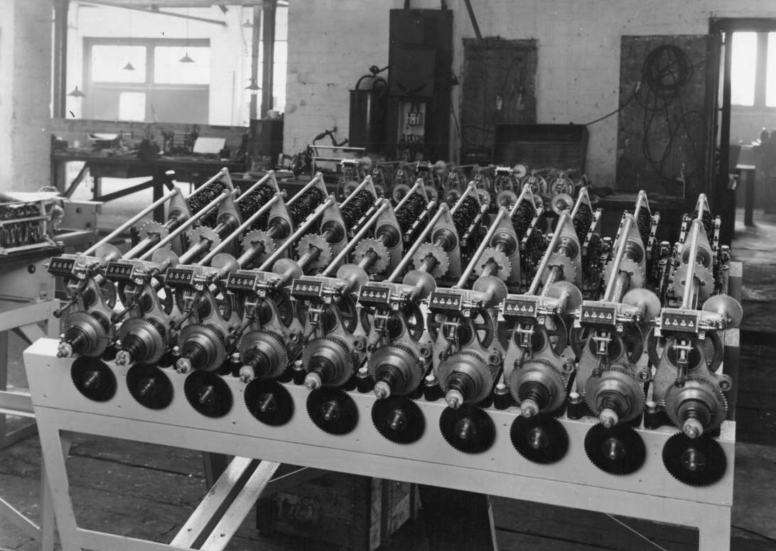
10- Single shaft 6 esc adding units on one frame. Labels omitted.The reference to 10- Single shaft 6 esc adding units refers to the ten constituent shaft adders at the rear of this complete adder. The Single shaft 6 esc describes these constituent shaft adders as having a single adding shaft each with 6 escapement wheels and associated escapement mechanisms, epicyclic gears and activation solenoids.
This represents one third of the Forecast Combination adding units since there are 30 possible combinations in a six dog race.
Taken in factory.
Regarding the comment there are 30 possible combinations in a six dog race relating to the Forecast pool, this pool has two runners selected in a single race that have to be placed first and second in the correct order. The possible winning combinations of runner numbers can be seen in the table below:
| 1-2 | 2-1 | 3-1 | 4-1 | 5-1 | 6-1 |
| 1-3 | 2-3 | 3-2 | 4-2 | 5-2 | 6-2 |
| 1-4 | 2-4 | 3-4 | 4-3 | 5-3 | 6-3 |
| 1-5 | 2-5 | 3-5 | 4-5 | 5-4 | 6-4 |
| 1-6 | 2-6 | 3-6 | 4-6 | 5-6 | 6-5 |
As the note on the back of the photo indicates, there are another two Adders the same as the one in this image required to operate the Forecast pool at Brough Park. The grand total adder is also required to calculate the investment on all the possible combinations that is necessary to calculate a dividend. The previous two images in this Photo Gallery show views of the GT Adder for Brough Park.
More after the image...
There is no photographer's stamp on this photograph
For much more detail on the storage screw have a look at the first two images in the Brough Park section of the Photo Gallery, the first can be viewed by clicking on this image and scrolling up and selecting the first thumbnail in the Photo Gallery index in the Brough Park Newcastle Upon Tyne 1936 section. Additionally, there is an Engineering Drawing of the storage screw in the first image of the Figures from George Julius' paper presented to the Institution of Engineers Australia in 1920 section of the Photo Gallery which follows the Brough Park section. There is also a drawing of a shaft adder adding shaft with its epicyclic gears and a drawing of a complete escapement mechanism in that section which are parts of the ten constituent shaft adders in the above complete adder.
The ten adding shafts are clearly visible across the whole rear of the adder occupying about a third of the footprint of this adder. They sit beneath the ten visible fixed support bars oriented front to rear which in conjunction with out of view support bars connect the two end plates of each of the ten adding shafts. The distant end plates of the adding shafts constitute the back of the adder. The shaft adder end plate supporting bars are the lower group of ten visible support bars. The higher group of ten visible supporting bars which are horizontally aligned with the lower bars run above the storage screws and assist in securing the front of the adder to the rearward section. There is an Engineering Drawing of the epicyclic gears and escapement wheels on an adding shaft in the second image of the Figures from George Julius' paper presented to the Institution of Engineers Australia in 1920 section of the Photo Gallery.
The escapement wheels on the adding shafts can be seen in the image above. Below these wheels are solenoids that operate the escapement mechanisms that allow graduated rotation of the escapement wheels. The solenoids are activated by impulses from the Ticket Issuing Machines (TIMs). There is an Engineering Drawing of an escapement wheel, escapement mechanism and solenoid in the third image of the Figures from George Julius' paper presented to the Institution of Engineers Australia in 1920 section of the Photo Gallery. Brough Park was a small installation with only eight TIMs. In contrast, also in the United Kingdom, the Julius Tote at White City London had multiple installations in the 1930s ending up with 320 TIMs.
The angular motion of these escapement wheels represents the transaction values. The fewer the teeth on the escapement wheel the greater the movement with one operation and the higher the value. The epicyclic gear arrangement that connects the escapement wheels along the adding shaft cumulatively adds the rotation of the escapement wheels along the shaft such that when it arrives at the storage screw the rotation is the sum of the rotation of each escapement wheel on the adding shaft. There are six escapements and solenoids on these adding shafts.
One of these shaft adder units is visible on the table to the left of this adder. Nine complete adding shafts attached to the storage screws and drive cogs can be seen behind the adder on display, on a table at the rear of the image, in the process of being assembled. The cogs attached to the adder table in the foreground, provide the drive for the adding shafts and storage screws and are driven by a motor that will be installed underneath the adder table.