This technology history page contains a photograph, which is one of several belonging to the photo gallery pages, which are part of several pages relating to the invention of the world's first automatic totalizator in 1913 and Automatic Totalisators Limited, the company founded to develop, manufacture and export these systems.
I have deliberately refrained from getting into a technical description of the adders here, as there are plenty of other pages in this website that provide the details. If you are interested in the workings of the adders, click on the top image then scroll to the bottom of the loaded page and select the Previous page navigation bar option. Next scroll down to the Miscellaneous Images heading in the Photo Gallery index and select the image thumbnail below with the descriptive text beginning with the sentence A three shaft adder viewed from the escapement end.
The barometer indicators shown in the fourth photograph in the Hialeah racetrack in Miami 1932 section of the Photo Gallery, are driven by this and the two other Julius Tote mainframes mentioned. Below the barometer indicators in that image are some selling booths with 11 of the 110 Ticket Issuing Machines (TIMs) installed on this track. To see this page, click on the top image and then select the image thumbnail below with the descriptive text starting with The Julius Barometer Indicators and Tote House.
The photograph of the grandstand which follows this photograph in the Photo Gallery probably housed this Julius Tote machine room.
In the Automatic Totalisators in America chapter of this website there is a Miami Herald article written in 1932 titled Hialeah Park's Australian Totalisator by Jack Bell. Following are a couple of extracts from that article.
Reprinted with the permission of The Miami Herald:
Here is a machine which takes your money, dumps it out the pot records the new total all over the plant, figures up the odds-then prints your ticket and hands it to you. And they tell me the machines will knock off tickets at the rate of 120 per minute...I fancy that I can just about imagine Jack's Southern Drawl just by reading his article! Of course I could be totally mistaken as I know nothing about him except what he has written in this Miami Herald article. For me, it makes his article far more interesting and it is evident that he has put a lot of effort into ascertaining the facts about this system and presenting it in a comprehensible and entertaining fashion. He also does an excellent job of conveying the incredulity of the people observing the installation of this, what at the time was unbelievable new age technology, the likes of which had not been seen before, as it predates electronic computers. I love the little gee-gaws and do-dads.All this sounds like a heluva a lot of mechanism, doesn't it. Well, it is. That's why the old-timers have joined the anvil chorus; they can't see how all those little gee-gaws and do-dads will ever keep going. We did a lot of wholesale figuring and found that by counting every bit of wire running from the machines to the various boards and other places, we have 195 miles- yessir, 195 miles of wire- running around in the form of cables and whatnot.
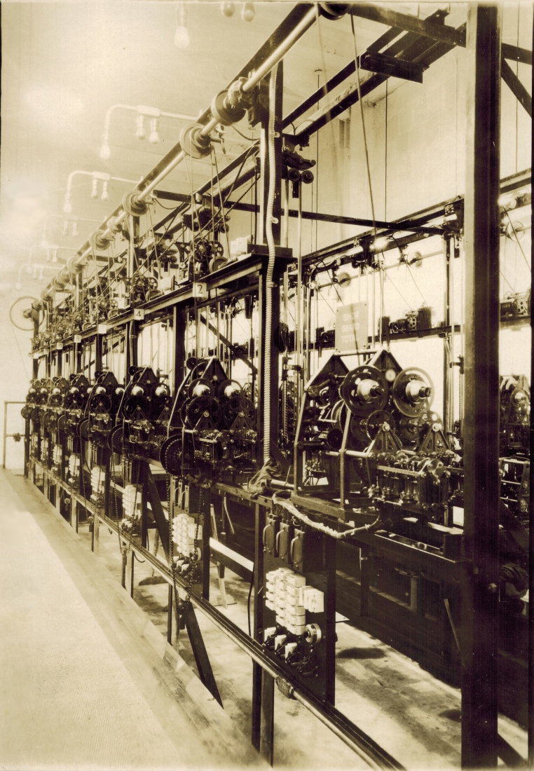
Jack also wrote the following in the same article, which contains a description of the mainframe shown in the top image, which Jack refers to as a larger computation machine. The deduction of tax he mentions as well as the calculation of odds is also performed by the mainframe in the top image. Jack indirectly mentions the Win pool in his comment let's say we are talking of the win bets, which I have deduced is the Straight pool so technically he is describing the Straight Pool mainframe at Miami but it will look exactly the same as the Show Pool mainframe in the top image:
Each "horse unit" (let's say we are talking of the win bets now) sends its bets into a larger computation machine as they come in. This machine continuously adds the money, sends the totals along to still another unit, which deducts 10 per cent for "the grand and glorious state of Florida (and may our taxes decrease!)," and the remaining 90 percent goes on to the machines which show the odds on the big board on the infield. These constantly changing odds, as indicated by the barometric readings on the board, are computed by use of a system of angles too complicated for me-and you, too. But it works.The reasoning I based my deduction that the Win Pool Jack refers to is the Straight Pool, is that Jack, in his article mentions three pools Win, Place and Show and my documentation refers to Straight Place and Show pools. Additionally, as previously mentioned, the fourth photograph in the Hialeah racetrack in Miami 1932 section of the Photo Gallery, shows a large indicator board at Hialeah containing odds for what are identified as Straight Place and Show pools.
To read the complete Miami Herald article, click on the top image then scroll to the bottom of the loaded page and select Go to the index navigation bar option. Next select the Automatic Totalisators in America Chapter in the Secondly section of the index. As previously mentioned, the article appears under the heading Hialeah Park's Australian totalizator.
There is a video clip titled "Opening Day Hialeah Park 1932" in the Video Clips chapter of this website, which has short segments showing the Julius Tote at Hialeah in operation. To see this video clip, click on the top image then scroll to the bottom of the loaded page and select Go to the index navigation bar option. Next select the Video clips of a working Julius tote Chapter in the Thirdly section of the index. The video clip thumbnail is titled hialeah1932.wmv (18.3Mb)Opening Day Hialeah Park 1932. The Julius Tote mainframe seen in the top image can be seen in operation in this video as the Operations/Maintenance staff monitor the system. It was said of the engineering staff that hearing as well as sight was significant in identifying particular faults. It seems that these systems were surprisingly reliable however. There is also a good view of the Julius Tote Raceday Control Panel being used that is installed at the totalisator operations centre of the racetrack to control the operation of the Julius Tote Mainframe shown in the image above.
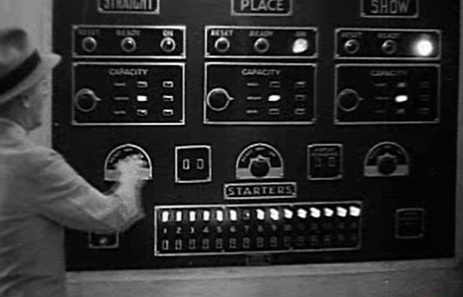
Julius Tote Raceday Control Panel in the Tote Control Room at Hialeah
Having mentioned that there is a good view of the Julius Tote Raceday Control Panel in the Opening Day Hialeah Park 1932 video clip, I have included the above image which is a frame from that clip. This control panel controls request and status lights in the machine room where the Julius Tote Mainframes are located, or it acts directly on the mainframe itself including the Show Pool mainframe seen in the image at the top of this page. The request and status lights in the Machine Room that this Raceday Control Panel above controls, are acted upon by the engineers in the machine room. One example of the Control Panel directly acting on the mainframe are the starter switches, seen at the bottom of the Raceday Control Panel image above, at the bottom of the control panel below the long row of illuminated lights one switch per light. The switches and lights are labelled 1 to 15 between the row of lights and the corresponding row of switches. This means that the highest number of runners in a race that can be catered for by this system is 15. This confirms the previous determination of the maximum field size of 15 for a race, from the number of horse adders in the mainframe in the image at the top of this page. The light corresponding to runner 7 in the control panel is extinguished, meaning that the corresponding switch is turned off and runner 7 is a scratching. A scratching refers to a scratched horse, which is one that is no longer participating in the race. As a result of the Starter Switch for runner 7 being in the off position Adder number 7 in the Mainframe image at the top of this page will be disabled. Lights can be seen mounted on arms projecting horizontally left out from the top of the frame in the image at the top of this page, over each of the horse adders. Each has three bulbs, one at the tip of the projecting arm on the down-going extremity and another two close together extending downwards from the horizontal part of the arm. In keeping with other installations I have seen, I am almost certain that one of these lamps will be a status lamp indicating whether the corresponding adder below is enabled or disabled by its associated Starter Switch on the Control Panel. Similarly, I am almost certain that another of these lamps will be an alarm indicating that the corresponding adder had one of its adding shaft springs completely unwind, indicating a drive failure and that a shaft is no longer adding its inputs. It is highly likely that the two lights close together on the horizontal part of the projecting arm are for these two purposes.
There is a close up view of a type of adder which were used in Melbourne, that is very similar to the ones used in this mainframe. To see this adder, click on the top image then scroll to the bottom of the loaded page and select Go to the index navigation bar option. Next select the The Melbourne Cup chapter in the Thirdly section of the index. The adder image is titled A close up of an adder from the system in the image above.