This page contains a photograph which is one of several belonging to the photo gallery pages which are part of several pages relating to the invention of the world's first automatic totalizator in 1913 and Automatic Totalisators Limited, the company founded to develop, manufacture and export these systems. It also describes the first computer based totalisator system in the Southern Hemisphere, which replaced a Julius electromechanical totalisator at Harold Park in Sydney. Finally there are papers presented at a Decus (Digital Equipment Corporation User Society) conference describing the software and hardware design of the PDP8 based totalisator systems.
Copyright © 1998 Email - totehis@hotmail.com
Historic Electromechanical Computing + PDP8 computer successor
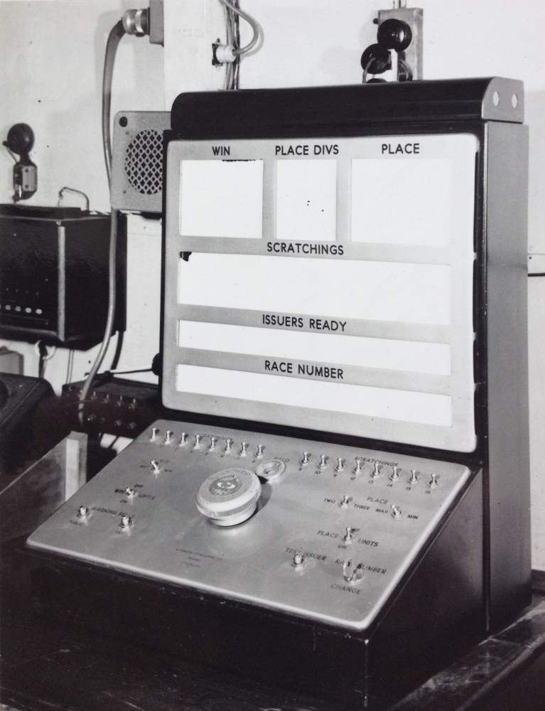
The image below shows a Julius Tote Raceday Control Console at Harold Park in 1958. This type of Raceday Control Console was used to set and display variables such as race number, field size, scratchings and the number of place dividends for each race. It also provided operational coordination between the machine room staff and the operations control staff and controlled the start and stop of selling operations. When the large knob in the middle of the Raceday Control Console control panel was rotated clockwise the race number was incremented. This caused a barrel embossed with the type for the race numbers, to be rotated to the next race number in every TIM for printing on the tickets. All the TIMs (Ticket Issuing Machines) clanked in unison as this selection was made. The scratching switches, visible in a long row at the top of the switch section of the control panel, disabled adders corresponding to scratched runners ensuring no bets could be registered on invalid runners. The white parts of the upper section of the control panel are lamp boxes containing bulbs that illuminated appropriate information indicating the status of the system when it was in operation. The function of these Raceday Control Consoles was eventually replaced by a computer application in the minicomputer era, although the early computer based totalisator systems still had hardware RDCs for a while. RDCs were later called TCCs (Tote Control Consoles.)
More after the image...
Electromechanical tote Raceday Control Console
To return to the Photo Gallery index, Click on the image above
If you arrived by navigating the website, use the navigation bar at the bottom of this page.
Photo by CAMERACRAFT PTY.LTD. Crane Place Phone: BU 1594
In a company document titled Automatic Totalisators Limited Description of Electrical Circuit Diagrams. In this there is a page titled LIST OF CIRCUIT DIAGRAMS DATED 15/5/1935. One entry reads 3488 - 'Reset'; 'Ready' and 'On' Signal Lamp Circuits, which is dated 10/5/1935 and is included below.
'RESET', 'READY' and 'ON' SIGNAL LAMP CIRCUITS / Drawing NO. 3488.
On the Control Room Switchboard there are two sets of three signal lamps marked 'Reset', 'Ready' and 'On', one set being for Win and the other for Place. There are six corresponding lamps on the Machine Room Signal Board connected in series with the above lamps.
When a race commences the machine is closed by the Steward, as described elsewhere. The Manager then turns his Win and Place control switches to the "off" position and the Head Mechanic also turns the Control Switches on the Main Switchboard to "off" position. In this position none of the signal lamps are alight.
When the manager has been notified by the dividend calculators that they have obtained the figures from the Adding Units, he turns his control switches to the 'Reset' position which lights the 'Reset' lamp on the Control Room Switchboard and the Machine Room Signal Board, thus notifying the mechanics that the machine may be reset for the next race.
On each Odds Unit there is a reset switch which is only closed when the horse slider is pulled right back to the reset position. All these reset switches are connected in series with the two 'Ready' lamps and in series with the Control Switches on the Main Switchboard. When the head mechanic is satisfied that the machine has been properly reset and is ready for the next race, he turns his control switches to the 'On' position and the 'Ready' lamps then light up provided that all horse slides have been set to zero. This notifies the Manager that the machine is ready for betting on the next race.
When the Manager is ready to open betting on the next race, he turns his control switches to the 'On' position and this, as described elsewhere, completes the circuit for the coils of the Win and Place contactors on the Main Switchboard. These...
Unfortunately, that is where this PDF file ends on the word These! I presume the remainder was either not worth photographing or it was missing. I will add to it the only comment that comes to mind, that it will presumably end with and lights the 'On' lamp.
The Control Room Switchboard mentioned above was often a fixed installation switchboard near the operations centre, which was usually located at the place of highest betting activity aside from what is called the Machine Room in the document, which in my time was the computer room as I only ever worked on computer based totalisators. A mobile version of the Control Room Switchboard was developed, presumably to reduce cost and allow for the possibility of moving the control centre in small to medium sized installations. This mobile version was called an RDC or Race Day Control console as shown in the image above.
The Reset', 'Ready' and 'On' lamps mentioned in the first paragraph of the document extract, relate to the RDC in this case, one set for Win and the other for Place. When the RDC is in operation the white areas on the vertical face of the RDC will have words appear on them, as there are lamp boxes behind these white facades and when a lamp is lit, the associated words corresponding to thinner layers of paint, create words. So inside the panels marked WIN and PLACE at the top of the the RDC above, are the words RESET, READY and ON in the top row, followed by a row with MAX MAX and a final row with MIN MIN. These are individual status lights that will illuminate when their corresponding lamp is on, indicating the particular status is active. The MAX MAX and MIN MIN status lights are part of the Capacity Signal Circuit explained below.
The first paragraph of the extract also mentions that there are a corresponding six lamps on the Machine Room Signal Board, which in the Julius Tote in the Eagle Farm Racecourse Museum sit above the mainframe in the machine room, one on above the Win pool related machinery and the other above the Place pool machinery. These status lights provide for a means of communication and coordination between the control room where the RDC is located and the machine room where the mainframe system is located.
The Reset status light illuminates when the associated Reset switch is turned on in the Control Room and the Ready status light illuminates when the associated Ready switch is turned on in the machine room, and the On status light illuminates when the On switch is set in the control room.
At the bottom of the inclined control panel in the lower section of the RDC above, in the fourth row of switches/buttons, there are two buttons on the left hand side labelled WARNING BELLS , the left button of the warning bell pair is labelled PUBLIC and the right PAY. On the right hand side of the control panel there is another button labelled TEST ISSUER that causes the ticket issuing machines to all print a test ticket and to the right of this is the CHANGE RACE NUMBER key. This locks the large circular knob in the centre of the control panel above, which is used to select the current race number. As changing the race number is a critical event, it has a key so the race number cannot be changed without authority and conviction of intention. I do not know, however I suspect that cycling the race number sets the RESET status lights.
In the row above these buttons and key, in the third row of buttons/switches on the left hand side there is a switch with the word WIN to the left of the switch and the word UNITS on the right. Above the switch the word OFF appears and below the word ON. This is the ON switch for the Win Pool that lights the ON status light that is the right hand light in the RESET READY and ON status light group in the WIN panel of the RDC, as well as the ON light at the bottom of the WIN Machine Room Signal Board above the Win pool processing equipment in the mainframe in the machine room. On the right hand side of this two switch row in the RDC, there is a switch with the word PLACE to the left of the switch and the word UNITS on the right. As before, above the switch the word OFF appears and below the word ON. This is the ON switch for the Place Pool that lights the ON status light in the PLACE panel of the RDC, as well as the ON light at the bottom of the PLACE Machine Room Signal Board above the mainframe in the machine room. These WIN UNITS and the PLACE UNITS switches are the Win and Place control switches the manager turns off, as described in the second paragraph of the document extract.
The PLACE DIVS section on the display face of the RDC above has four status lights in it, arranged in two rows containing TWO TWO and THREE THREE, again not visible as the RDC is turned off. The left hand status lights TWO and THREE are controlled by a switch in the inclined control panel part of the RDC, in the row above the previously described WIN UNITS and PLACE UNITS switches also second row from the top. The two switches on the right hand side of this row are labelled PLACE, and the left hand switch of this pair, is the switch that controls the left hand status lights TWO and THREE. This switch is labelled TWO on its left hand side and THREE on its right side, and as already mentioned has the word PLACE, which appears above a position between it and the next switch to the right. With this switch in the left position, the left hand TWO status light in the PLACE DIVS display on the RDC will illuminate. This is a request to the mechanics in the machine room to configure the system for a two Place dividend. With this switch in the right position, the left hand THREE status light in the PLACE DIVS display will illuminate. Similarly, this request to the mechanics in the machine room, is to configure the system for a three Place dividend. The mechanics in the machine room, see this request on the Place Pool TWO/THREE dividend Machine Room Signal Board at the Place pool end of the mainframe in the machine room.
There is a similar switch to the one in the RDC, which the Chief Engineer sets in the machine room, when he is satisfied the number of place dividends has been configured correctly. Now the TWO/THREE dividend Machine Room Signal Board and the TWO/THREE status lights in the PLACE DIVS section on the display face of the RDC should either show TWO TWO indicating a two place dividend has been requested and configured or THREE THREE for a three place dividend. An indication of TWO THREE or THREE TWO indicates the place pool machinery is not ready for operation.
Moving on, immediately to the right of the switch in the RDC above, that specifies the number of place pool dividends as two or three, there is another switch that shares the word PLACE located above and between the two switches. On the left of this other switch is the word MAX and to the right MIN, identifying this switch as the Place Pool MAX/MIN request switch. The leftmost switch in this row of three switches has the word WIN on top of it, with MAX on the left side and to the right MIN identifying it as Win Pool MAX/MIN request switch. This switch controls the left hand status lights in the second and third row of three that appear in the WIN status panel of the RDC when it is powered up. As previously mentioned the first row of status lights in this panel of the RDC contain RESET, READY and ON statuses, the second row contains MAX MAX status lights and the third and final row are the MIN MIN status lights. The Win Pool MAX/MIN request switch will either illuminate the left hand MAX status light or the left hand MIN status light. Similarly, the Place Pool MAX/MIN request switch on the RDC will either illuminate the left hand MAX status light or the left hand MIN status light in the PLACE status panel of the RDC.
The Win pool MAX/MIN status lights and the Place pool MAX/MIN status lights are visible on Machine Room Signal Boards. As before, when the system has been properly configured in the machine room for a place pool minimum or maximum capacity the Chief Engineer places the associated machine room Place MAX/MIN switch in the position that confirms the setting leading a status display in the second or third row of the PLACE panel on the face of the RDC of MIN MIN OR MAX MAX with MIN MAX or MAX MIN being no go situations. The same applies to the Win Pool, when it is properly configured in the machine room, the Chief Engineer places the associated machine room Win MAX/MIN switch in the position that confirms the setting leading a status display in the second or third row of the WIN panel on the face of the RDC reading MIN MIN OR MAX MAX.
In the previously mentioned document titled Automatic Totalisators Limited Description of Electrical Circuit Diagrams another entry in the page titled LIST OF CIRCUIT DIAGRAMS DATED 15/5/1935 reads 3487 - Capacity Signal Circuit which relates to the Win and Place MAX/MIN status lights and is dated 10/5/1935. A copy of this entry which provides more information on this circuit is shown below. A preliminary comment relating to the extract below is that some of the larger Julius Totes had three settings for the Capacity Circuit, Maximum, Mean and Minimum. The Julius Tote at Harold Park where the RDC in the image above was installed, only had two, Maximum and Minimum.
Capacity Signal Circuit / Drawing NO. 3487
Each adding unit is provided with 3 chain sprockets of different sizes. The chain which controls the movement of the horse slider of the corresponding Odds Unit may be placed on any one of these sprockets and thus the movement of the horse slider in relation to the number of bets registered may be varied. This enables the Odds Unit to cater for the largest race, when the chain is on the small sprocket, without reaching the end of its travel, but by placing the chain on the largest sprocket greater relative movement of the slider can be achieved for small races thus giving greater accuracy of the Odds Unit.
Similarly the rate of travel of the grand total sliders, in relation to the total bets registered on the grand total, can be changed by means of a change speed gear in the gear box unit, the changes being proportionate to the changes provided by the three chain sprockets on the horse units.
To ensure correct indication of the odds on the barometer indicator it is essential that all horse units and the gear box unit be set on the same capacity. The capacity required for a particular race is selected by the Manager who has a capacity selector switch on the Control Room Switchboard. This switch has three positions, namely, Maximum, Mean and Minimum. Alongside this switch are three pairs of red lamps. On the machine room signal board there are a similar set of six lamps connected in series with the corresponding lamps on the Control Room Switchboard. When the manager sets the capacity selector switch to, say Maximum the Left Hand Maximum signal lamp will light on both the Control Room Switchboard and the Machine Room Signal Board, thus notifying the mechanics that the Adding Units are to be set for Maximum capacity.
On each horse unit there is a three position switch which bridges a different pair of contacts in each position. The switch is moved from one position to another when the capacity of the unit is changed by moving the chain from one sprocket to another. There is a similar switch on the gear box controlled by the gear change lever.
The corresponding pairs of contacts on all the switches are connected in series with the corresponding right-hand signal lamps on the Control Room Switchboard and Machine Room Signal Board. Thus the right hand lamps will not light unless all units have been set on the same capacity as the capacity set by the manager on the selector switch. This enables the manager to check that all units have been set according to his instructions.
The Control Room Switchboard mentioned in the third paragraph of the extract above, later often had this functionality implemented in Raceday Control Consoles like the one shown above. The capacity selector switch, which the manager uses as mentioned in the third paragraph of the extract, of which there is one for each pool, I have already described as the Place Pool MAX/MIN request switch and the Win Pool MAX/MIN request switch. As previously stated the Harold Park Julius Tote had no Mean setting. The lamp status lights for the confirmation of capacity settings is replaced with the PLA/MIN PLA/MIN or PLA/MAX PLA/MAX and WIN/MIN WIN/MIN or WIN/MAX WIN/MAX status light pairs in the Brisbane system.
In the previously mentioned document titled Automatic Totalisators Limited Description of Electrical Circuit Diagrams yet another entry in the page titled LIST OF CIRCUIT DIAGRAMS DATED 15/5/1935 reads 3486 - Escapement Alarm and Starter Lamps Circuits which relates to the scratchings switches and the active adder status lights and is dated 10/5/1935. A copy follows:
Escapement Alarm and Starters Lamps Circuits / Drawing NO. 3486
Starters Lamps:
On the Control Room Switchboard there is a bank of switches, one for each horse, for the purpose of cutting out all horse units except for the actual starters in the Race.
Immediately above each of these switches there is a small red light which lights up when the corresponding starters switch is closed thus giving a visual indication as to which starters switches are closed.
On the machine frame immediately above each horse unit there is a white light which lights up when the corresponding starters switch is closed on the Control Room Switchboard and serves to indicate to the mechanics which units are in operation in the race.
Escapement Cutout and Alarm Circuit:
Each horse unit is provided with automatic cutout relays which interrupt the betting circuit and so prevent further betting, if for any reason the adding gear fails to keep pace with the escapements.
At the end of each escapement shaft there are a pair of slip rings with brushes bearing on them. One slip ring is attached to the escapement shaft and moves with it, and the other is attached to the driving gear which drives the escapement shaft by means of a spring and stop pegs. When escapements are tripped the escapement shaft rotates under the action of the spring and the driving gear, which is driven from the motor through a slipping clutch, follows up and rewinds the spring until brought to rest by the stop pegs.
Should the driving gear for any reason fail to follow up the escapement shaft the latter will rotate under the action of the spring for about three quarters of a revolution when a pair of contacts, one on each slip ring, will close together. The closing of these contacts completes the circuit for the trip coil of an escapement alarm relay on the adding unit fuse board. The tripping of this relay interrupts the common feed to all the escapement magnets on the particular escapement shaft concerned, and prevents further betting on these escapements.
There is an escapement cutout relay for each escapement shaft on each adding unit so that if, for example, the drive to No.1 escapement shaft on No.6 Win Horse Unit fails then only No.6 Win Contact on the issuers connected to the escapements on this shaft will be put out of action, thus reducing the amount of shut-down to a minimum.
One side of the trip coils of all the escapement cutout relays are connected to a common return wire which is connected in series with the trip coil of an alarm relay on the main switchboard so that the tripping of any escapement cutout relay also trips the alarm relay which completes the circuit for an alarm bell and so warns the mechanics that the fault has occurred.
When an escapement cutout relay trips it closes another contact which lights a red lamp above the horse unit concerned and so enables the mechanics to locate which unit is at fault without delay.
These relays are hand reset and must only be reset after the fault has been located and rectified.
As with the previous extract, the Control Room Switchboard mentioned in the first paragraph of the extract above, has its functionality implemented in the RDC as shown in the image above. As can be seen in the RDC above, in the first row of switches on the RDC, which are arranged in two groups of 8 switches, with each group labelled SCRATCHINGS, are the bank of switches, one for each horse, mentioned in the first paragraph of the extract above.
In paragraph two of the extract above, instead of the small red light, which is above each of these switches, in the RDC image mentioned, there is a display panel that spans the width of the RDC which is labelled SRATCHINGS which indicates which adders, or horse units as they are referred to in the extract, have been disabled by the bank of switches.
In paragraph three of the extract, it mentions On the machine frame immediately above each horse unit there is a white light. These lights can be seen on the mainframe in the Eagle Farm Racecourse Museum, above every adder, where they appear as illuminated runner numbers in the mainframe, except the grand total adders. Any runner numbers not illuminated indicates the associated adder is not active in the current race, disabled by the SCRATCHING switches in the RDC.
A full transcription of the company document titled Automatic Totalisators Limited Description of Electrical Circuit Diagrams can be read in the second page of the Photo Gallery of this website. To read this, click on the image at the top of this page, then scroll down to the bottom of the page and select the Next page button in the Navigation Bar at the bottom of the page. Now scroll down to the heading Figures from George Julius' White Paper 1920 and a Julius Tote Engineering Drawing, then scroll further down and select the blueprint thumbnail with the first sentence of the associated text reading This is a technical drawing showing Julius Tote interconnections.
In Brisbane, which was my domain when I worked for Automatic Totalisators Limited, these devices and the other electromechanical tote facilities were replaced by PDP11 based computer totalisator systems, which I worked on. The software application which replaced these hardware Raceday Control Consoles was named RDC an acronym for Race Day Control. When the PDP11 system was replaced by a VAX based system this application ended up with the name TCC, an acronym for Tote Control Console. In Brisbane, this transition from electromechanical to computer based totalisator system, took place later than at many other tracks, which first transitioned to a PDP8 computer based system, as did Harold Park.
The first transition Electromechanical to Digital Computers
The world's first of these electronic totes was developed by ATL (Automatic Totalisators Limited) for the New York Racing Association at Aqueduct. To read about this system, have a look at Aqueduct which is in the Automatic Totalisators in America chapter. The PDP8 totalisator system ATL installed at Harold Park was the first Electronic Totalisator in the Southern Hemisphere. The PDP8 minicomputer that this totalisator system was based on was manufactured by DEC an acronym for the Digital Equipment Corporation. Most of ATL's computer totalisator systems were based on minicomputers designed and manufactured by this corporation. DEC was the number two computer company in the world next to IBM around the end of the 20th century. I have included the following information from Rob Stone who was a computer engineer at ATL who worked on the PDP8 installations at Harold Park and Wentworth Park. It seems appropriate to present Rob's information here as he mentions the Tote Control Console, or as he refers to it the TCC. Rob's TCC, although it was part of a computer totalisator system, was not a pure software application like the one in Brisbane. Like the Julius tote Raceday Control Console at the top of this page it still was a custom built hardware console performing similar functions. There is a direct link between Rob's TCC and the image above as the one in his PDP8 system replaced the actual Raceday Control Console shown in the image above.
My short time at Harold Park, starting with an introduction to Totalisator Operations as I knew nothing about totalisators when I joined the company and later repairing difficult to identify faults, was associated with the PDP11 computer tote that replaced the PDP8 system Rob is writing about. Another connection between the Julius Totes and Rob's PDP8 systems is that his computer based totalisators, unlike their successors the PDP11 systems that I worked on, replaced more Julius Totes. As a consequence, an electronic device called a scanner was developed to interface the PDP8 systems with Julius Tote electromechanical TIMs. These electronic scanners replaced the Julius Tote front end system of the same name and interfaced to the PDP8s instead of the electromechanical shaft adders. Hence the PDP8 based systems were capable of interfacing to the old J8 TIMs (Ticket Issuing Machines) from the electromechanical Julius Totes, saving customer Race-clubs the expense of replacing all their TIMs. David Hamilton, the ex ATL New South Wales Operations Manager, indicated in the first page of the Memories of an Ops Manager and Harold Park chapter of this website, that there were two kinds of electromechanical TIMs used with this installation at Harold Park, the J8 and J10. I have also read that 114 new J11 TIMs were part of this new system. The J11s were specially developed for use with minicomputer systems. There were some J15s included in this project as well. The new system operated on Win Place Quinella and Doubles pools. To read about the J11 see A J11 TIM which is one of the images in the Photo Gallery Continued chapter.
Rob's Display Boards in Chaos anecdote, which he mentions below in his memories of Harold Park, is very interesting to me as it illustrates a basic principle regarding testing software before it goes live. This principle that I have noticed is that no amount of software testing will identify all software bugs in complex systems. When performing rigorous software testing, which is critical, there comes a time when you go beyond the law of diminishing returns. Once this point is passed, you start dreaming up nightmare scenarios which are highly unlikely to occur in live operations incurring unfruitful expenditure and delays. In other words there is a practical time to go live with a new computer system to see what real problems remain. I am convinced that many computer systems actually retire with undiscovered bugs as a result of a scenario envisaged and catered for in the software design, which never eventuates in the lifespan of the system, leaving the associated code never executed.
The Display Boards in Chaos problem Rob relates when the Harold Park PDP8 system had newly commenced operation, is one that I regard as a nightmare scenario that would in all probability not have been dreamt up during the testing phase of this system no matter how long it had been subjected to testing. The ultimate success of a system depends on how the problems revealed after going live are dealt with. It is the sort of action that Rob took after going live that resulted in the problem being rectified quickly, which is essential for the ultimate success of a system. Oh and a bit of luck is very helpful as Rob points out, as his problem manifested itself at the end of a race meeting, minimising the impact duration. In the decades that I was responsible for the engineering of totalisator systems in a remote branch, the best case scenario was to have a local development system. This eliminated the delay involved in reporting the problem to and waiting for head office to provide a solution to a software problem. In the best case scenario of having a local development system, a rectified version of a program containing a newly discovered bug could be up and running at the same race meeting that the bug was discovered. Another big advantage of a local development system is that in the event of finding a more complex bug, you could rebuild a failing program to include the debugger and gain a lot more information about the fault whilst the fault conditions were present. This saved the time required trying to recreate the circumstances that caused the problem after the operational system has lost the fault trigger information as a result of commencing the next operation. This procedure often greatly expedited the ultimate solution.
Finally, relating to the Display Boards in Chaos problem, Rob makes a reference to a well known totalisator operations problem, that if punters can't see the odds they don't bet.
Rob Stone's memories of the Harold Park PDP8 totalisator
I worked for ATL for 3 years, from Jan. 1970 to late 1972, initially as a Tote System Installation Engineer under Peter Rolls, and later in the Research Dept under George Klemmer.
I was given responsibility for installing the computer systems at Harold Park and Wentworth Park, supported by Peter Rolls, Ron Hood, Kevin Franks etc. in Installation, George Klemmer and team in Research, Dick Sterndale-Smith and programming team under George, Neville Mitchell Alf Lesins and team in the Drawing Office, and Alan Lakeman Bill Johnson and team on track.
After Harold Park was up and running, as far as I can remember, there were very few operational dramas, except for one memorable Saturday night.
The dog meeting was going smoothly, right up until 5 minutes before the last race (Race 10). This was when the TAB off-course betting data was entered into the on-course pools before each race, by an operator using an old ASR-33 teletypewriter (you remember them, don't you?). Webmaster's Note: Yes I do remember them. I used them as a student. There are a couple of images of one below with associated text "An ASR33 Teletype on the left and a close up of the ASR33 Papertape Punch on the right."
Suddenly, absolute chaos descended as all the odds display boards on course "went crazy". Random draft dividends were displayed as the updates rippled down each column on the boards, then were overwritten as it went back to the start immediately and clobbered that data with further random dividends. This is all just as the majority of punters were waiting to see the changed odds after the off-course betting was added, before placing their final bets.
Very soon, Alan Lakeman and co. burst into the computer room, naturally demanding "Rob, what's going on???". I had already had time to take the first course of action, which was to take the B computer off-line, see no effect, put it back on-line, then take the A computer off-line, and (unfortunately) see no effect there either.
Of course, everyone wanted to know "How can the punters place their bets if they can't see the odds?" Unfortunately, the answer was: Either they have to go on the last displayed odds, or sorry, they don't bet.
As both computers were issuing chaotic but identical behaviour, I'd had to conclude that it was a software problem, and told Alan this. I said that therefore there was nothing else that could be done at the time, but just to keep our fingers crossed and hope that that the betting data stored in memory was safe (no disks in those days), and that the computers would stop accepting bets when the race started, and could then calculate the right dividends when needed. Fortunately (phew!), it was the last race of the night, everything else except the odds indicator boards appeared to function OK, and the race and night completed successfully.
Also fortunately, I had been able to observe exactly what had happened just prior to the calamity, and reported the details (I think with a printed memory dump), to Dick Sterndale-Smith first thing Monday morning, who was straight onto it. In entering the off-course betting info on the ASR-33, the operator had made a mistake, and had gone into a 'correct' or 'edit' mode, using 'Backspace'(s) etc. Unfortunately while in this mode, she made another error (probably under the pressure of hurrying before betting closed), and tried to correct that. And that's when "all hell done broke loose, boy".
In all the software testing that had been done, that was one combination of events that hadn't been anticipated, and the program tried to store part of the double-corrected data in the area of memory where the indicator board update program code resided - thus sending that software routine haywire. Also fortunately, that routine was the last in the memory map, and so other program code had not been affected.
Happy ending - The problem was fixed promptly by our software colleagues, and I don't recall any other significant incidents during the commissioning and hand-over periods at both tracks.
Webmaster's note:
Rob's crippling fault caused by a software routine overwriting memory dedicated to storing instructions, reminds me of a similar problem in Brisbane. It was a bug overwriting a critical variable storing the Win Pool Grand Total, resulting in intermittently displayed erroneous massive investments on CCTV and Indicator displays around the track. I remember it well as it was difficult to isolate because it was not possible to reproduce the symptoms in a test environment. We had J11 chip based PDP11s acting as protocol converters and the problem was in the firmware of these devices. These protocol converters converted TAB synchronous HDLC protocol, to the on course asynchronous digital communications protocol. This link sent the on course pool figures to the TAB and the TAB returned the figures for the whole of Queensland.
This was a significant problem, as it had the propensity to encourage punters to wager much more than they would have otherwise, unless they realised these massive investment figures on display were erroneous. Unlike Rob's condition, this problem manifest itself on multiple occasions and at the most undesirable times, only at big meetings. As it was not possible to recreate the symptoms, the only means of resolving the problem was to run versions of the application with debug code I had written to report pertinent parameters whilst running live at these big meetings. I determined that we were not receiving any odds messages with inflated win pool GTs from the TAB. The incoming messages from the TAB were being stored in a forward linked closed loop linked list. I implemented some debug code to report on parameters associated with this list.
Analysing the resulting debug information, it became obvious that under normal operations the linked list never wrapped around. The wrap around feature was only used if the reading procedure did not catch up with the writing procedure before the writing procedure got to the end of the buffer which unfortunately only occurred during the bigger and more important meetings. Furthermore the corrupted win pool grand totals only occurred when a wrap around occurred after getting to the end of the buffer and starting at the beginning overwriting already processed messages. Consequently I scrutinised the software that managed the wrap around. I found that the writing procedure would overflow the end of the buffer by two bytes before wrapping around. The two extra bytes overwrote a word allocated to the variable used to store the Win Pool GT. I changed the firmware source to wrap around at the real buffer limit and the problem was solved.
And just reflecting on (gentleman) Alan Lakeman at Harold Park, I recalled a conversation with him that will stay with me forever:
Rob (reporting an equipment problem): "It's not working".
Alan: "What do you mean it's not working?"
Rob: "It's cactus f**ktus".
Alan (feigning shock & horror): "Rob! I'll have you know that I'm a lay preacher!"
I'll always remember the look of mock horror and indignation on Alan's face, before we both fell about laughing ... A memorable incident for me.
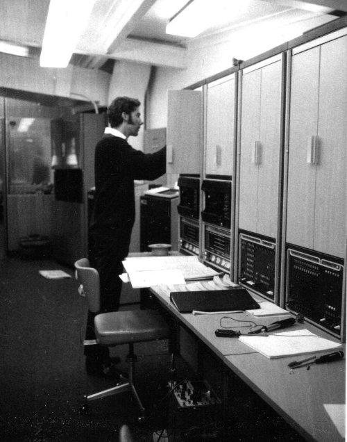 Rob Stone with Duplex PDP8 system at Harold Park 1970
Photo supplied by Rob Stone:
The PDP8 based totalisator system shown above was Australia's first computer based totalisator system. Furthermore it was the first computer based totalisator system in the Southern Hemisphere.
Webmaster's note:
I love this image! Although I started with Automatic Totalisators Limited working on the following generation of computer totes based on the PDP11, this image makes me feel completely at home. The computer consoles, the register lights, the paper-tape readers, the workbench, the paper-tape programs, the notes, the Biro, the documentation, the reel of wire-wrap wire, the screwdrivers, the solder sucker, the Tektronix CRO (Cathode Ray Oscilloscope) standing on the floor on the near side of the chair slightly under the bench, a very familiar workplace to me. The Tektronix 465 is a model of CRO I have spent much of my life attached to, it could be me in this image! Home Sweet Home! In all the staged publicity and sales photos it is all clinically clean, however this image shows it the way it was for the engineering staff and represents the workplace that I spent far too much of my life in!
Back to Rob Stone's memories:
Workday at Harold Park
The systems at Harold Park and Wentworth Park used duplex or twin PDP-8/I's, each with 16K words of memory. (Note: that's only approx 16,000 x 12-bit words to store all of the program, the variables, and all the betting data!). But as the interfacing to PDP-11s was developed during my 3 years at ATL, I believe that the following tote systems manufactured were soon based on the PDP-11s (the first being the PDP-11/20s).
The photo above was a real 'on-the-job' working snapshot in time. As Brian mentioned above, all of the tools visible in the photo - from the small spool of wirewrap wire, to the Tektronix 'scope almost hidden from view, indicate that it was probably in Nov. or Dec. 1970, during the installation and testing phase, before Harold Park went live in Dec. that year. The area I'm working on was a wire-wrapped panel which held the DEC discrete component R-series and W-series logic cards that interfaced the computers into the 'twin' configuration, and provided the latching and buffering of data from the computers, for handling by the other cabinets in the system. The other cabinets as I recall were, from the left:
- The "Interface", which defined and handled which computers were on-line, and interfaced to the TCC (Tote Control Console) and the following equipment.
- Two electronic Scanners, each of which was a cabinet of R- and W- logic cards (in a wirewrap panel) that scanned 64 TIMs, to see if any had grounded their 'bid' wire, then controlled them.
- The BCU (indicator Board Control Unit), which had logic boards for latching data and selecting the lampboxes to be updated next, and also the relays that released the latching voltage from each lampbox group in turn (which dropped out the lampbox relays and hence their displayed digits), before a digit code was applied to each selected lampbox, if it was not to be blank.
Webmaster's note:
A backplane panel, like the one Rob is working on, hidden from view by the door, is shown in the image below titled The PDP8 Backplane. The double doors immediately to the right of Rob hide the second such panel belonging to the second PDP8 computer. The first pair of longer doors to the right conceal the Interface panel backplane that contains the associated logic boards. The Interface Control Panel can be seen between the bottom of these long double doors and the bench. A close-up view of this type of panel can be seen in the image below titled The PDP8 Interface from Harold Park. Finally the last pair of doors on the right hand side of the image conceals the first Scanner backplane that contains its associated logic boards. This electronics provides connection to the Ticket Issuing Machines. The Scanner Control Panel can be seen between the bottom of this last pair of long double doors and the bench.
When being updated, each lampbox would receive a "2 out of 5" code on 5 parallel wires, which then displayed one of the 10 digits, 0 to 9. The "2 out of 5" code was a safety feature so that if a fault occurred activating (say) 1 or 3 of the 5 data lines, an irregular light pattern would be displayed (indicating an error), rather than displaying the wrong odds digit.
Webmaster's note:
Rob describes the Tote Control Console (TCC) next. Following is an image of a PDP8 totalisator system TCC, taken in the Automatic Totalisators Limited Meadowbank factory, which was for the Hong Kong Happy Valley system. Bob Plemel in the photo on the left, was the longest serving and most productive engineering manager I knew at ATL. He was a major mentor of mine.
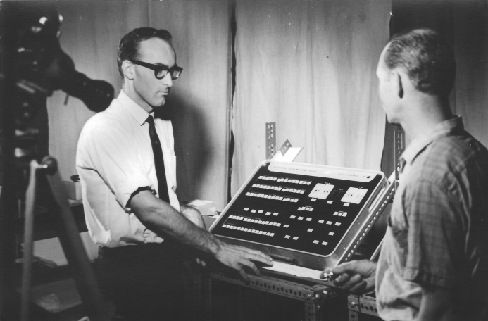 Bob Plemel and the PDP8 TCC
The TCC at that time was the physical input device that controlled the tote operation, after the programs were started in both computers. It was a neat, smart-looking desk-top panel, on about a 20 degree slope towards the front, fitted into a shallow housing about 2 ft wide, by say 15 - 18 inches deep, a few inches high at the front and about 6-7 in. high at the back. It had the full complement of illuminated push-buttons to indicate Race No., non-scratched starters, which pools were active, 'Start' and 'Stop' betting, 'Calculate Divs' when the results were official, etc. It sat on the bench opposite the computer system, next to the wide computer room window, where the operator could see race starts, 'Results Official' type indicators, etc
When a TIM locked in a bet request, it would ground its bid wire (1 for each machine), seeking access to the Scanner mentioned above. The Scanner would cycle around its 64 TIMs in turn (at the rate of about 5000 checks per second), and when it found a 'bid', it would stop on that TIM and provide an enabling voltage to the TIM, which gated its bet data on to 3 or 4 groups of 8 parallel wires (no serial communications at ATL at that stage), using a "3 out of 8" code for each significant TIM figure. The Scanner would then interrupt whichever computers were on-line and present the data for processing by the computers. Each computer would separately analyse the data bid from the TIM, and issue an 'Accept' or 'Reject' independently to the Scanner. If the responses agreed, the Scanner would issue either a 'Confirm' to the TIM and the ticket would be printed, or a 'Reject' and the TIM keys would be released with no ticket printed.
If the responses disagreed, or if no response was received from 1 computer within the time allowed, the Scanner would freeze, with bid data and the 2 responses displayed for the engineer to analyse. At which point, 64 TIMs were being held up, and the engineer had to quickly look at the bid data, assess whether it was a valid bet or not, whether betting was still current on that race or not, decide which computer was right, and take the other computer off-line with the flick of a switch on the Interface. That allowed the ticket to be accepted or rejected by just one computer, and freed the Scanner to move on to checking the other 63 TIMs.
As the computer processing time for each ticket was a small fraction of the time taken to actually print a ticket, and because each Scanner could move on to the next TIM as soon as it allowed a TIM to latch the Accept or Reject response, from memory, a Scanner could issue responses to all 64 connected TIMs within 1 to 2 seconds, even if all 64 had locked in a bet bid at virtually the same time.
On a software note, each computer in the duplex or twin system ran independently, but each computer set and cleared a flag which was incorporated into a synchronisation loop. My understanding of the mainline logic was that it consisted of a list of checks for inputs from all of the connected system equipment described above, as well as housekeeping tasks, (recalculating odds, printing betting and dividends information after a race, etc), plus the setting, checking and clearing of the sync flags. The loop was used as it was very important that each computer saw the same information at exactly the same time (or as closely as was possible), so that there wasn't a situation where the computers were processing bids from 2 different Scanners at the same time (as both would lock up waiting for the other computer), or where one computer could process a bet just before the "Stop Betting" signal while the other processed the same bet just after the "Stop". So at the start of the sync loop, each computer would set its sync flag, then wait (probably a very short time) for it to see from the Interface that the other computer had set its flag. At that point, each would clear its own flag and move off in 'lock-step' down the mainline program code, processing inputs and outputs as it went, until it came back to the 'top' of the sync loop, to repeat the process again.
However, I have digressed. Back to the photo .... (Webmaster's clarification: Photo above titled Rob Stone with Duplex PDP8 system at Harold Park 1970)
As wiring or design faults were found in our testing, it was necessary for the Engineer (yours truly in this case) to work out the change needed, remove the incorrect wire-wrapped connections, put the new ones in using a wirewrap gun, and re-test to see if that had fixed the problem - as well as checking that I hadn't added a new fault.
Seeing the complement of tools and equipment in the image, my guess is that the photo has caught a "technical field change" in progress at the time it was taken. If a change merely corrected a wiring error, where the connections didn't match the wiring diagrams (normally 20 to 36 x A3 pages per unit), it was just a matter of fixing the connections. If the wiring had been correct, but the logic needed changing to achieve the objective, I'd also mark up a copy of the wiring page(s) and send it(them) back to Neville in the Drawing Office to be updated and re-issued.
A Tricky Printing Problem
While integrating and testing the Harold Park system in the front test room at Meadowbank, before it was moved to H.P., a highly unusual printing problem turned up.
The symptoms were (are you ready for it?): All printouts from the tote software would print reliably on the DEC line printer (80 columns - I think it was imaginatively labelled as an 'LP-80'), except for when a prior page printed on less than half the page, and was followed by a 'Form Feed' command (skip to the start of the next page), the first line of print on the next page would be completely scrambled to any random characters that the printer could produce!
OK, before you see the reason, bets are being taken on the final cause and solution.
As it only ever occurred after a Form Feed operation, the tote software was checked first. Nope - even a simple custom diagnostic program could reproduce the problem.
Oh dear - Rob has compelled me yet again to sing my accord! Webmaster's note:
Any self respecting minicomputer hardware engineer at the time worth his salt was very well acquainted with the architecture of the computer he was working on. It was a common requirement of the fault finding process to be able to write short machine code diagnostics which were loaded into memory using the console and executed to provide pertinent information on a specific problem.
Old reliable Tektronix 'scope to the rescue. Fault finding in the printer logic revealed that when it was doing a Form Feed, AND when the page drive mechanism got up to full speed after a prior half-empty page, the servo paper drive logic with speed detection and feedback loop would go into oscillation (at about 200kHz, from memory), superimposing a massive high-frequency signal onto the D.C. drive voltage to the paper-drive motor. Unfortunately, the wiring from the control logic to the motor was held in the same wiring loom that carried data from the data socket at the back of the printer to the printer buffer memory. The printer had a 1-line buffer that would be accepting the next line of print from the computer as it was printing the current line, and so Bingo! .... When the servo paper drive system went into oscillation, the radiation into the data logic wires scrambled the data for the next line, which was of course the first line on the next page.
When the printer was new (and tested by DEC), there was no slack in the motor drive belt or bearings etc., and the logic kept tight control over the speed of the paper movement as it followed a smooth ramp up in speed until it (maybe) hit full speed, then a smooth ramp down in speed, leaving the paper at just the right spot to start the next page's printing. Beautiful when it was new. But as the printer aged and some mechanical slack came into the system, if the paper drive got to full speed, the feedback would try to keep it 'idling' along at the same speed, which set up the scene for oscillations when the control was designed to be too 'tight'.
Webmaster's note:
Yes I know, I know, why don't I just let Rob tell his story? Well he introduces so many pertinent observations of a whole field of work, computer component level repair that no longer exists due to the vast majority of machines these days being throw away replaceable items, that I feel compelled to add emphasis. Additionally, the not so technical readers will not be aware of the significance of writing which presumes a technical readership. Having attempted to justify my continuous interruptions, for the not so technical readers this is an interesting fault to anyone who maintained computer hardware in the minicomputer/mainframe era, or to any computer technologist interested in the history of computer technology.
Rob's "Tricky Printing Problem" is an obscure circumstance for a well established product! A burst of electromagnetic radiation is inducing interference from a paper advance motor drive to neighbouring data lines, due to a hunting closed loop servo system. This resulted from mechanical slack in the motor drive caused by time related wear! This would not be on the initial list probable causes when considering such a fault. Consequently this has the earmark of a challenging fault, requiring a meticulous analytical approach to identifying the problem after eliminating the most probable causes first.
The fix:-
I determined that as the paper movement had to follow only a smooth ramp up and down in speed, over a period of 1 to 2 seconds, the feedback loop (which worked well) didn't need to have a frequency response of 200kHz. So I simply lifted a wire connection in the feedback signal, inserted a modest value resistor (probably 100 ohms, for example) in series, then put a small capacitor (say 0.1 microF) after the resistor, to earth - the simplest low-pass filter you can have. Bingo again! ... The printer still did its Form Feeds reliably, but no more oscillations under any circumstances, and hence no more scrambling of printed data.
Webmaster's Note:
I just can't help myself, it just strikes such an accord with me. I love Rob's solution! There is an acronym that I have heard in multiple fields of engineering, KISS: Keep It Simple Stupid. According to KISS philosophy, all other factors being equal, Rob's solution is the simplest effective solution and for that reason, it is probably the best.
As this is a history page, I will mention the KISS philosophy seems to stem from the work of a 14th century English Franciscan friar William of Ockham. It is also referred to as Occam's razor. Essentially, Rob did not repair the fault as that in all probability would have required additional time and expense replacing the motor and parts of the drive system. Instead he found a lateral thinking solution by redesigning the electronics to cater for the mechanical problems.
I tidied up the modification, wrote up the problem, its cause, and the field change I had done, and sent it all to DEC - whom I hope took action to modify their design and retrofit any change to existing printers. I had to put the same change into the second Harold Park printer and the 2 for Wentworth Park.
It was fortunate that the problem showed itself before the systems went live, as our only record of the betting details, totals and dividends that the system produced were the printouts after each race, on the 2 on-course system line printers. Remember - no discs in those days.
Webmaster's final Note on Rob's section:
David Hamilton, who was the ATL NSW Operations Manager at the time the PDP8 system was introduced, also remembers the introduction of the PDP8 system in his tote memoirs in the Memories of an Ops Manager and Harold Park chapter.
Information and Images from Max Burnet ex CEO Digital Equipment Corporation Australia
On hearing that a web page of the Automatic Totalisators Limited's, Harold Park PDP8 system was being developed, Max contributed the following information with two very rare images:
In 2001 I was given two items by Bill Johnson of Stockton for the BACK museum collection. They are still safely on show at my house. I enclose a pic of each of them.
Webmaster's Note:
Max mentions the BACK museum which is a magnificent computer museum he has set up in his home belonging to his company BACK Pty Ltd (Burnet Antique Computer Knowhow.) Max's museum is breathtaking to behold and I am not even going to attempt to describe it here as it will become voluminous. Additionally, Bill Johnson Max mentions was a long serving engineer and manager at ATL who has contributed significantly to this website.
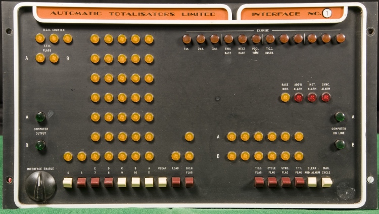 The PDP8 Interface from Harold Park
Photo by Max Burnet and Peter Watt:
The front panel was made by ATL and provided information and control for the dual PDP-8 configuration.The two computers were simply called A and B. Either one could be the master. The panel used the same colour and style as the PDP-8 front console..
Rob Stone, who wrote the previous article above, added the following comment about Max's PDP8 Interface image:
Right on the money, showing the A and B computer output selection buttons and other indicators, as mentioned in our correspondence. And that Interface panel & cabinet can be seen right next to the 2 PDP-8s in the Duplex photo. Webmaster's note: The Duplex photo is shown in the image above titled Rob Stone with Duplex PDP8 system at Harold Park 1970.
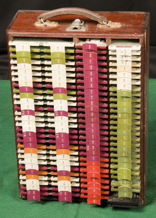 Wooden Box of PDP8 Spare modules for rapid repair
Photo by Max Burnet and Peter Watt:
The wooden box held a set of spare electronic DEC modules as used in the PDP-8's. Bill said he had the half an hour between the races to find and fix a fault. In those days DEC provided the customer with a recommended list of spare parts to have on hand.
The bright and colourful module handles in the above photo all had a purpose in life...
The purple handles indicated the module comprised Integrated circuits and were used for the PDP-8/I computers.
The red handles indicated the module comprised transistor based logic and were used for the interfacing equipment.
The white handles indicated the module comprised passive components such as wiring connections, lamp drivers etc
The green handles indicated the module was used to support the core memory of the computers. They had very tricky analog/digital circuitry that could make a grown man cry!
The orange handles indicated the module comprised analog circuitry.
At the bottom right of the photo is an extender board. A suspected failing module could be mounted in this extender, and examined with afore-mentioned oscilloscope.
Webmaster's note:
So much of what is written is in accord with me and my memories that I feel compelled to write more about it! Max has pointed out the extender board. Having spent so long in repairing electronic equipment and in particular DEC minicomputers I can relate that these extenders played an essential role in the work I performed.
Only a few faults could be identified statically. Failing this the faulty board had to be powered up and in operation to identify the fault. This meant it had to be on one of these extenders so the faulty board sits proud from all the other boards exposing the circuit components. This allowed the attachment of the aforementioned oscilloscope, as Max puts it, or other test equipment, to pertinent nodes in the circuitry with a probe. The only difference with my experience is that the extender board in this image is a single height extender board, meaning it can only extend boards that only have one backplane connector unless you use more than one of these extenders. As I worked with the PDP11 computers, most of the PCBs (Printed Circuit Boards) I worked with were hex height boards, meaning there were 6 of these connectors in a row on the one circuit board and hence the extender had 6 as well.
I notice that in the left half of the box in the image above, the boards are all dual height which means it takes two extenders like the one in the image to extend these boards. You can see that in the two left hand columns of handles, the left hand handle is on the same circuit board as the right hand handle. In contrast, it can be seen in the right hand two columns of handles that the left and right hand columns are attached to separate circuit boards. There were a few dual height boards in the PDP11s I worked on, like the Bootstrap/Terminator boards and the main memory Parity Controllers.
 Go back to the index Go to the bottom of the page
William Johnson made the following comment about Max's wooden box:
Lynne's father, my father in law made two of the boxes for the spare cards. Always carried between Harold Park and Wentworth Park. We cycled the cards through the computers to make sure they were always working.
Webmaster's note:
There it goes again, I am a firm believer in the principle William just mentioned! If you are fortunate enough to have spare modules, you have to have a system of ensuring they remain functional. This is called ensuring you have viable spares. It is no good leaving them unused for ages, then in a crisis when you desperately need one you find your spare has developed a fault in the elapsed time since it was last used. Yes that does happen, electronic equipment can develop faults during long periods of not being used or by being manhandled whilst transporting them.
Max later added the following images and observations:
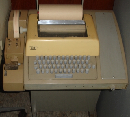
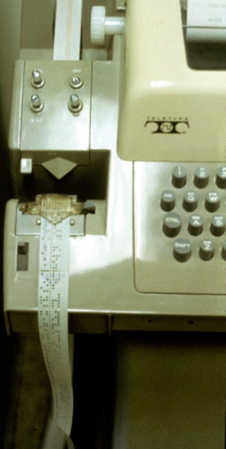
An ASR33 Teletype on the left and a close up of the ASR33 Papertape Punch on the right
Photos by Max Burnet and Peter Watt:
Webmaster's note:
These images show an ASR33 terminal which were the mainstay terminal in the era of this computer room. Rob mentions the ASR-33 Teletypewriter in his article above relating to Display Boards in Chaos. This is the type of terminal on which the operator triggered the indicator problems. The blank papertape can be seen at the top left of both images where it comes off the reel and in the right hand image the punched tape can be seen below the punch where it dangles off the bottom edge of the terminal. I can well remember using these terminals to write and store programs written for a Data General minicomputer in my student years.
In the image above titled Rob Stone with Duplex PDP8 system at Harold Park 1970, in the cabinet he is working on and the one to his right, immediately below his elbow are two black looking devices one in each rack, above the two PDP8 consoles which are immediately above the shelf. These are papertape readers that read the punched tape seen hanging from the right hand ASR33 image. (To Max, my apologies for the Data General Appello Non Grata, no disrespect intended.) -For the non technical reader I apologised to Max for the Data General reference which was a competitor of the Digital Equipment Corporation founded by a breakaway group from the latter.
On reading the above comment on Data General, Max wrote the following:
Our aforesaid arch rival, Data General, started with integrated circuits, so gave DEC hell about needing a bus converter. As a result we often gave away the bus converter for free and buried it deep in the 6 foot cabinets!
Webmaster's Note:
I have taken Max's comment above out of sequence and placed it here to connect with the Data General reference. As a consequence the need for a bus converter is explained in Max's information following:
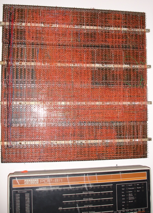 The PDP8 Backplane
Photo by Max Burnet and Peter Watt:
Back to the information provided by Max.
When Rob Stone talks about re-wiring the PDP-8/I, this is the daunting wiring complexity that he faced. The photo shows the PDP8I backplane. Factory wiring was done in red. Field changes were usually done in yellow.
Webmaster's note:
For the not so technical reader, the image above titled The PDP8 Backplane is a close up view of what Rob is working on in the prior image above titled Rob Stone with Duplex PDP8 system at Harold Park 1970. As there is no yellow wiring on the backplane shown here, as Max points out, there has been no Field Changes performed on this backplane. Rob will be using yellow wire in the photo with him in it.
The first PDP-8 that DEC made around 1965 was made of transistors and diodes.(These were the R for red modules). Over time it has become called the "straight" 8, or the "classic" 8.
In my DEC aust history DVD there is a list of straight 8's on page 13 and 14. It shows ATL had two of them, serial numbers 564 and 740. They were probably in the ATL :"research dept" or "development lab" By their serial numbers I would estimate they were bought around 1964. (It sounds like Bill Johnson gave one of these to the university when it reached end of life).
The PDP-8/I was made with integrated circuit ( M for mauve) modules about 1971. The 4 at Harold Park and Wentworth Park were PDP-8/Is.
There was a major discontinuity between the two which was not featured very much. The straight PDP-8 had an I/O bus that was 0 to -3 volts. The PDP-8/I had an I/O bus that was 0 to plus 5 volts. This meant a whole new generation of peripherals had to be developed for the 8/I. Or use a cumbersome bi-directional "bus converter".
That explains why the box of spare modules has both red and mauve modules in it.
Retirement of these PDP8s from Tote life
When one spends a lot of time with systems, one gets attached to them and often wonders what became of them. Bill Johnson wrote the following about the PDP8 Tote systems at Harold Park and Wentworth Park:
I bought the 4 PDP-8s from Harold Park and Wentworth Park. Eventually sold them to deserving technical persons. The first PDP-8, all transistor, from research I gave or sold to my nephew Max and it ended up outside the maths department at the University of New South Wales.
In the same email Bill wrote the following, which was pertinent to me as I too worked for ATL and AWA and I have a long standing connection with Australian Aviation and probably used the aircraft beacons mentioned, which from the mention of towers and the era were probably ADFs (Automatic Direction Finder). I can well remember AWA's significant involvement in Avionics:
My brother Jeff while programming at ATL was asked if he would go to Indonesia for the installation. There was a "discussion" relating to alterations in conditions with Indonesia so Jeff did not go. He had previously worked in Indonesia for AWA installing aircraft beacon towers and electronics.
Memories of this era from Neville Mitchell
Neville Mitchell was a long serving Engineer and Manager at ATL and is the best company historian I know. Neville has been mentioned above by Rob Stone. Over to Neville:
I attended the DEC training course with Allen Lakeman in Crows Nest, with Bill Johnson and Ray Stone.
Webmaster's notes:
Ray Stone is Rob Stone's brother. (Postscript: I eventually and coincidentally met Ray in November 2017 well after this page was written. It was at the Max Burnet Computer Old Timers Luncheon. The Luncheon was organised by the Australian Computer Society and Max invited Narelle and I to sit at his table.)
Additionally I have included the following reference to Wentworth Park as this system followed shortly after the Harold Park system and is mentioned by Rob Stone above.
I recall the problem Rob Stone had with one of the high speed printers at Wentworth park. He spent many hours analysing the fault that turned out to be the printer drum which consisted of two print wheels on a single spindle one of the print wheels had loosened and moved out of alignment thus printing the wrong characters.
George Jenkins was also involved with me on the Wentworth Park CCTV system. We had completed the CCTV installation and it was working satisfactorily, then one morning we discovered a 50 cps hum bar rising horizontally on every monitor. I was at a loss to know where the interference was coming from, I called George to come and assist. It turned out that over the weekend the electrical contractor MW Ellison had altered the power points in each monitor housing adding earth wire from the GPO to the actual housing. The City Council Inspector had issued an E notice requiring the monitor housing be earthed, unfortunately the old Ledger grandstands electrical wiring was leaking to earth this ground voltage was the cause of the hum bar. The added earth wire was totally unnecessary as the monitor housings were bolted to the steel grandstand structure. A quick trip around the housings with a step ladder and a pair of side cutters did the trick.
I don't think MW Ellison's electrician at WP would question the Electrical authority's direction to earth the monitors GPO to its steel housing even given the housing was bolted to the steel grandstand structure. I knew the MWE electrician very well he was a Dutchman ex POW in Germany during WW2, he knew more about the Tote cabling of Randwick, HP & WP tracks than ATL did. He could terminate large W/P cables onto those ATL open frame terminal frames as neatly as the Women in the factory. Frank was a excellent artist, he had a love of aircraft especially fighters, he could do a wonderful water colour painting of a dog fight with English and German planes so realistic. Frank lost his life, when a power pole at Randwick collapsed.
At that time the two inspectors that regularly did inspections of works carried out by the on-course electricians, were a Mr Dear and a Mr Love. (Truly!) They even had leather bound copies of SAA3000 the bible of electrical work standards. I had studied it back in the 1950's when at Tech. ATL did follow its directives when it came to power connected manufactures. Anyway one day Messrs Dear & Love turned up at Harold Park. We had just finished and were testing the new large Ledger indicator. They came into the indicator and looked around at the systems and the 100 or so lamp panels. They sighted the data cables terminal block coming from the computer room on the paddock side of the track, "What are those Green wires?" they asked, They are part of a set of five data connections that fed the indicator with its 2 of 5 code. "You can't have green wires as green is always a earth wire" they said and began to write up an E sheet. The reason they were insistent on us changing the green wires was that the Paddock computer room was on a separate Power Grid system to the Ledger. About this moment, Ron Hood turned up and somehow convinced the inspectors that it was lunch time and he invited them to dine with him at the local Harold Park Hotel. I never did see an E sheet, or for that matter, did I ever come across Messrs Dear and Love again!
Webmaster's Note:
Ron Hood was my first Manager when I joined Automatic Totalisators. I thoroughly enjoyed working for him as he afforded me the time to do a lot of study relating to ATL products and their engineering. So long as I had my head in a manual, an engineering drawing, or a diagnostic listing, he was happy. I learnt a lot from Ron! There is an image of Ron Hood in the Memories of the factory continued chapter of this website. In February 2016 Neville Mitchell added the following about the Harold Park and Wentworth Park PDP8 tote projects.
The memories keep flashing back, of those weeks we spent day and long nights doing those installations. Often driving home with the sun just coming over my back, instead of as usual, driving into the sun on a normal days start. That was a great team spirit, among the people doing the two installations, we were all rewarded with the satisfaction of its great success.
I was project manager for the Wentworth Park installation. Opening night went flawlessly, I was wandering after the last race, when a group of ATL people, engineers, managers and operators approached me. I was quickly lifted onto Joe Norris's shoulders, and paraded around in front of the new tote house and the towering indicator board. Joe later told me, in all his tote life, he had not seen two openings so smoothly carried out.
Actually this was the second time I got the shoulder treatment. Early days at Randwick, I had to arrange for the removal and re-installation of what was known as the Grand Piano. A billiard table sized device that controlled all the results and dividend Shutter Blind displays. Each display control was a knurled wheel, operating a potentiometer which was one leg of the Wheatstone bridge's digit display circuit that operated each blind. (Same as the adders for odds.) The local staff kept telling me it will never work again, in three days I had it all working. Then I spent lots of time uselessly trying to get the Visitel Judges results device to work. On the Friday when the operating staff arrived and fully tested the Dividend & Results using the rebuilt Grand Piano, they were so delighted they just picked me up for a joyful parade in front of the Leger Tote indicator. Then Don Hardie arrived wanting to know why It took so long to do the job. I explained that we had spent 2 of the 5 days trying to get the Visitel working. Don burst into peals of laughter saying The bloody thing never ever worked properly!
The Thing about Friction
Friction in the workplace can be counter-productive, however it can also be the companion of progress. Rob Stone and Neville Mitchell wrote to each other, observing friction incidents at work. I have presented it here as I too have experienced exactly the same thing they observe. Like Rob relates, I have also been asked at times to consider, that in diligently documenting engineering work I am eroding job security. Rob also mentions a type of technical problem I have encountered. Sometimes in multiple board electronic devices, the technical documentation for the board electronics can be impeccable however the documentation on how the boards interconnect can be sadly lacking. On the other hand some companies had perfect documentation throughout. Two such perfect documentation companies whose equipment I have had a lot to do with are the Ampex Corporation and the Digital Equipment Corporation. I can recall being very impressed with the Ampex manual set for one of their broadcast standard Videotape machines, possibly the AVR2, as they even provided notes on Op Amp (Operational Amplifier) Theory. Reading this was like having a refresher course if your Op Amp Theory was rusty.
Following is an extract from an email that Neville sent to Rob:
Alf was my manager when I first moved from production to electrical inspection. He was an Estonian, trained in a Russian tractor factory's drawing office. I normally got on very well with him. When I returned from several overseas installations I would be re-assigned to the drawing office. I had learned a lot about the old tote machines, which was good, but I wanted to design peripheral gear for the burgeoning PDP8 era. I clashed with Alf and Talis over engineering failures regarding notable voltage drop over 120 & 50 volt ticket machine power lines for J8, J10 and J11. There is a lot of voltage drop with DC currents and race tracks are usually large places with long power lines. Other long held old fashion methods were strictly held to, so I was the new Upstart causing some dissension in the office.
Following is an extract from Rob's reply to Neville:
Talking about striking resistance when you see something that can be improved: When I was putting the tote systems together and testing them at Meadowbank, I would frequently have trouble finding where a particular signal (say XYZ-12) came from or went to, when it was on a different page of say a scanner (with perhaps 30 pages of circuitry). Some signals would have page refs in brackets after the signals if off-page. But when I started adding page refs to signals, after spending the time to find them, or adding explanatory notes to pages where needed, our good mate Ron took me to task, using the reasoning: "Rob, if you dot every 'i' and cross every 't', they'll be less dependent on us experienced guys for explanations, setting up the systems, and the training of the overseas system engineers!"
I still snuck in (with your drawing office) whatever clarifications I could, whenever I got the chance.
On the subject of lack in interconnect documentation, Neville added the following:
Rob brings up the point about documentation. In the PDP8 days I often wondered why there was no general schematic for the PDP8 computer assembly, as Rob said several senior engineers kept certain crucial interconnection details to themselves. I would look at all those ribbon cables in Harold Park and Wentworth park and wonder to myself how they got there. The same applied to the Victorian PDP34 systems.
Thinking back there was never, that I discovered, a total schematic of a Julius electromechanical totalisator system. There was ample documentation for each component part but no interconnecting schematics.
Two extracts from "ATL International Name in Totalisator Betting Systems"
ATL electronic totalisator system is the pacemaker at Harold Park
Harold Park Paceway has been host to many great trotters including Cardigan Bay, who won a million dollars in Australasia and the United States, and Lucky Creed who won 23 successive events. Their performances will be talked about at Harold Park for as long as people remember the time Dan Patch broke the two minute barrier for a mile at Yonkers. And that will be forever.
Harold Park Paceway was the first racecourse in the Southern Hemisphere to install an Electronic Totalisator System.
ATL did the job, its tenth successful Electronic installation since Aqueduct. This year there will be 89 race meetings at Harold Park, 47 of them for trotters and 42 for greyhounds. All will attract huge crowds, for this racecourse is the most important venue of its kind in Australia.
The N.S.W. Trotting Club, the company controlling Harold Park, at the moment can boast of having the most modern Totalisator facilities anywhere in the trotting world.
Main features of Electronic System
I have included this second extract from the company document "ATL International Name in Totalisator Betting Systems", as Rob Stone mentioned being the installation engineer for Wentworth Park as well as Harold Park and Wentworth Park has been mentioned multiple times throughout this page.
Twin computers combine on-course and off-course investments at Wentworth Park. Closed circuit television is used to transmit Odds, Results and Dividends information throughout the Course for both public and internal use.
As an added feature, the running of each race is videotaped and played back to the patrons on monitors 2 minutes after the greyhounds have crossed the finish line.
The Computer Room incorporates the TAB off-course and ATL control offices in a fully air-conditioned area which is located in the Paddock Totalisator House and overlooks the track.
The Electronic Totalisator System is capable of serving 128 Ticket Issuing Machines selling Win, Place and Quinella tickets in the range of 50 cents to $50.
High speed Line Printers record the information stored in the computers. This information is available for checking and for record purposes at any time.
Logging Teleprinters record all instructions given to the computers and type out data as specified by the program. Instructions not taken care of by the program are keyed into the Totalisator Control Console which serves as an input device.
Calculations of Odds and Dividends are made by the computer under program control. The Lamp Boxes in the Indicator Board are activated by the Board Control Unit which is part of the computer complex.
Five selling divisions equipped with type J11 single value Win, Place and Quinella Ticket Issuing Machines serve the betting needs of the public. Both types of machine are fast lightweight press button units designed to efficiently and speedily handle business at the selling windows.
A new grandstand with many special design features is envisaged in future plans for Wentworth Park. ATL shares with the Wentworth Park Trust and the National Coursing Association their enthusiastic anticipation of this plan becoming a reality, thus providing another facet to the modern facilities offered at this internationally-known greyhound race track.
Technical Documents from Dick Sterndale-Smith
Dick Sterndale-Smith was a long serving programmer at ATL. From memory, he was the Chief Programmer when I joined the company. He is mentioned above by Rob Stone. On May 25 2015 Dick wrote:
These stories have got me thinking about that era, but most of my memories seem to have faded over time, not withstanding all the people that I was fortunate enough to work with along the way. I remember I made the front page of Tote Topics, sitting at the PDP8 console toggling in that bootstrap program to get the thing started. We did know that program off by heart.
Webmaster's notes:
Tote Topics that Dick mentions is the Automatic Totalisators Limited company magazine which was produced quarterly. There is a page of this website that presents articles from these magazines in the Tote Topics chapter.
Dick also mentions the bootstrap program that was known off by heart. This is a simple program that loads the binary loader which in turn loads the operating system. These days this program is contained in firmware and automatically executes after the system is powered up. In the minicomputer era, these bootstrap loaders were normally manually entered. As this was a regular event, which was required each time the system was powered up, it was expeditious to learn it off by heart. For those who did not have to perform this function regularly there was often a copy of this program visible on the computer hardware. In the image above titled The PDP8 Backplane there is a PDP8 console shown below the Backplane. Near the left hand edge of the console, inside a white rectangle there is part of a copy of this bootstrap loader visible. It is titled Rim Loader consisting of two rows of octal numbers which are the addresses and their associated instructions. RIM is an acronym for Read-In Mode, which in this case is the name of the bootstrap loader.
One thing I have in my possession is the "Proceedings of the Decus-Australia May, 1971 Symposium", where George Klemmer and myself presented papers which I have attached for your info.
Webmaster's note:
Decus-Australia that Dick mentions was the Australian chapter of the Digital Equipment Corporation User Society.
Lastly, the one thing I will never forget working at Harold Park was the Friday(?) night that Kerry Packer joined us at the track with a few of his mates. I was in the dinning room having dinner when the entourage arrived looking for seats. Not sure if they had a reservation or not, but besides Kerry the only other person I remember was Tony Greig, the cricketer. Of course after they had arrived, the word soon got back to the stewards that the famous man was here, and a laky was dispatched to invite him to the Stewards box. All that I overheard was KP politely declining the offer, and stating he preferred the company of his mates (who may not have been invited).
Following is major content from Dick's documents:
A REAL-TIME TOTALISATOR - SOFTWARE ANALYSIS
R.F. Sterndale-Smith
Automatic Totalisators Limited
Meadowbank. N.S.W. 2114
Abstract
A real-time totalisator operates under a duplex philosophy with all functions divided into either foreground or background tasks depending upon their priority or importance. Foreground and background concepts are reiterated and illustrated. The format and content of each transaction through the system are discussed together with the error detecting steps taken. Major and minor priorities of background tasks are defined as are the data representation and storage requirements of different betting types.
INTRODUCTION
The electronic totalisator is a real-time betting system providing for the selling and recording of bets on races, together with a cycled display of odds and the subsequent calculation of dividends for winning bets. The system operates continuously from the start of the first race and cycles race by race until the completion of the last race.
The totalisator program can be divided into a foreground interrupt service routine and a background Executive (EXEC) program. All functions are similarly divided into these two groups - foreground and background depending upon the priority or importance of the task.
FOREGROUND MODE
Each foreground service routine is associated with a peripheral. So, with the interrupt facility enabled, hardware flag settings immediately interrupt both processors, stalling the EXEC or job program in progress. Their position and state are stored with control being transferred to a supervisory routine. This routine polls all the device flags and transfers to the foreground routine unique to the device.
With the single interrupt level, all foreground tasks have a higher priority than background tasks and must not share routines with background tasks since no special re-entrant steps have been taken. Foreground programs have a positional priority based upon their place in the skip chain. Devices first in the chain are those with the highest priority (e.g. power low detection and scanners) or frequency of occurrence (e.g. the line printer).
It is a necessity in this real-time application that all input to the system be accomplished in the foreground mode. In particular keyboard input, buffered and left for processing by the background program, may be overwritten before the EXEC reaches it, if processing time is consumed by other foreground servicing. With the processing being done in the foreground and the echoing in the background, the problem of losing a character before echoing is still present. A stack is needed to store the characters prior to echoing them.
As mentioned all processing related to input is done in the foreground mode, so that this implies all device loops are associated with output peripherals.
BACKGROUND MODE
The EXEC consists of a main control loop and as many device loops as there are peripherals whose output operations will be overlapped with processing. Control moves cyclically around the device loops and only enters those which are not already occupied in data transfers. To this end, each device loop has its own busy indicator and an address pointer related to the position that the EXEC has reached in completing a task.
If a device loop is free when interrogated from the main control loop, the EXEC commences checking for jobs or tasks that are waiting. When a job indicator is found set, the EXEC releases control to that job. These indicators can be set from the foreground mode, or alternatively after background processing to signal the readiness of data to be outputted . Job indicators that are set, eventually result in an IOT instruction being issued; whereupon the busy indicator is set, the address pointer is updated and control is returned to the main control loop. After the device flag has been serviced (in the foreground mode) by the clearing of its flag, and clearing the device busy indicator, the device loop is once more free and the EXEC can continue in a similar fashion with the task until completion.
Whilst routines cannot be common to both foreground and background modes this does not preclude routines being shared between different device loops. Two conditions must be satisfied. Firstly the routines may not contain IOT instructions, since the EXEC could progress to other device loops where the routine might be called again for the loss of the first return address. Secondly, data pertinent to these routines cannot be stored in common storage areas.
COMPUTER SYNCHRONISATION
Both computers operate asynchronously in terms of their cycle times, but after checking all device loops i.e. each time the EXEC is transversed, both the computers must wait for each other before they step off once more. This degree of synchronization is accomplished by testing a single flag in each computer which is skipped on if both are set and again if both are cleared. The interface circuitry emits an audible and visible alarm for a lack of response from either computer.
LOGIC LOOP
In addition to the device-oriented loops, there exists a loop related to no device, but compatible in structure with the rest. It is termed the LOGIC loop because it maintains the structure or logic of the device loops, and is responsible for passing from the foreground to the background, calculations which justifiably belong to the latter. This is accomplished by foreground routines changing indicators which belong to the LOGIC loop. All LOGIC loop tasks are those which exclusively involve processing and consequently its busy indicator will never be found set and is superfluous. Its pointer is still used though, so that the flow of information to other peripherals is not inhibited by the relatively long period spent in calculations. Some functions then are only completed after a number of passes through the EXEC, which is analogous to the operation of the device-oriented loops. After completing the calculation, another indicator change flags a device dependent loop to initiate the output of the resultant calculations.
TOTALISATOR CONTROL CONSOLE COMMANDS
The sequence of events during a meeting is controlled from the Totalisator Control Console (T.C.C.). Here commands such as STOP BETTING or COMPUTE DIVIDENDS are initiated, which execute as foreground tasks and pass control over to peripheral dependant jobs by the setting of job indicators as described under the Background Mode Section. All T.C.C. commands, which do not directly produce hard copy, are logged on the teletypes with the following information: race number, current time and date.
Webmaster's note:
There is an image above of the T.C.C. that Dick refers to titled Bob Plemel and the PDP8 TCC.
Most T.C.C. routines can be separated into three phases. The first is the validation phase where it is determined if the 6-bit byte presented at the interface is legal. The next phase, which is not always present, requires that the command pass a series of logical tests, such as not allowing START BETTING unless a field of runners has been entered. The final phase consists of the response or action. Upon failing any pre-requisite, the command is not attempted, rather a diagnostic is logged, together with an audible alarm being sounded.
MAJOR & MINOR PRIORITIES
Central to the whole tote program is the calculation and display of progressive odds and finally the calculation of dividends for the results of a race. Both tasks have a certain intrinsic level of urgency i.e. a major priority in that they cannot be stalled by earlier request upon themselves. These tasks are distinguished from others in that their output is capable of self-interruption. Hence if dividends have been computed for incorrect results, new dividends can be recomputed before the termination of the normal dividends printouts.
There is one exception to this priority status though and that is the RACE INCREMENT task. It is pressed once per race and involves moving current race data into previous race data areas and for the Doubles, previous race data into penultimate areas. Thus because of its singular importance, the printouts from this instruction are incapable of interruption. As a general rule, previous race data areas are only accessed by routines that compute dividends. Dividends are therefore only calculable after RACE INCREMENT and can be re-computed any time up until the next RACE INCREMENT in the case of a protest being upheld.
The minor priority is only associated with the calculation of odds and is a function of how it relates to other jobs which also want to re-calculate odds before a previous set have been fully utilised. This minor priority works on a "first come first served" basis with the proviso that further requests are not queued, instead they take advantage of a current set of figures. Then after the last odd has been posted, and only then will the next request be honoured with an updating and recalculation of odds.
The major priority jobs are of course capable of breaking this dependence, whereupon the interdependent task is started again from the beginning.
TICKET ISSUING MACHINE TRANSACTIONS
The data associated with each transaction from a Ticket Issuing Machine (T.I.M.) is presented through a scanner to the computer in four 6-bit bytes. The first data word has one of two formats depending if the bet involves a single runner or a combination of runners.
| Single Runner Transaction: | Combination Runner Transaction: | The second data word consists of: |
|---|
| BYTE No.1 - bet type or pool code | BYTE No.1 - 1st leg runner code | BYTE No.3 - value code |
| BYTE No.2 - runner code | BYTE No.2 - 2nd leg runner code | BYTE No.4 - T.I.M. number |
BYTES No.1 and No.2 are variable data dependent upon the transaction and are supplied from the T.I.M.
BYTE No.4 is implicit in the current position of the scanner.
The above data must be processed by sorting firstly on its pools and runner combinations and secondly on its T.I.M. or scanner address. If betting is not open, a REJECT signal is returned to the T.I.M. If betting is in progress, then the transaction must be validated to insure that no transmission errors have been made by checking data bytes Nos. 1 to 3. This data is now ready to be sorted on its pool type Win, Place, Quinella, Double or Forecast etc., and the pool processing branches continue checking with the following elementary checks being typical:
- Is the pool operating this race?
- Is the runner valid (i.e. not scratched) for this race?
After adding the value of the bet to both the runner total and T.I.M. totals, a CONFIRM signal is sent to the T.I.M. via the scanner. The ticket is now physically printed and the scanner looks to grant service to any other requesting T.I.M.
REJECT signals belong to one of two classes, with both inhibiting the printing of a ticket and releasing the keyed information.
A REJECT No.1 is used if betting is off or for a bet on a non-runner.
A REJECT No.2 is used for an illegal data byte.
Invalid data, all four data bytes together with the scanner number is stored in a cyclic buffer, so that faulty transmission or encoding of data can be located and rectified.
DATA STORAGE
All runner totals are held as double-precision integers. The total being an integral multiple of a unit or minimum bet. By storing all information on runner combinations, a progressive total of money bet on each runner or combination is maintained and at the end of betting, these are the final totals. The size of data storage areas is known in advance and relates to the maximum number of runners that the tote equipment is designed to accommodate. For PDP-8 systems, a field of 12 runners is preferred.
WIN & PLACE
Win and Place are two distinct pools, with one dividend usually being paid in the win pool and two or three in the Place Pool depending upon the number of runners. These totals are stored in vector form. 1-origin index referencing is used and since there are two words per runner, the total length of the vector is 2r, where r is the maximum number of runners in the field. 1-origin indices were chosen to preserve the correspondence between runner numbers and vector elements. Hence a bet on horse number i, i.e. W[i] or P[i] is stored at the address starting at, B + 2(i - 1), where B is the base or starting address of the vector.
QUINELLA
Quinella bets correspond to nominating the first two runners past the post in any order so that 1-2 bet pays a dividend if either one took first place and two second or vice versa. Totals here are again stored as a vector instead of as a matrix which would be more than half sparse. This amounts to considerable core saving when such storage areas may be repeated up to ten times in a system program. The total money wagered on Q[i,j] is stored in the double precision address starting at, B + r(r - 1) - (r-i+1)(r-i) + 2(j-i-1).
DOUBLE
Double bets correspond to selecting the winner in each of two races and are stored as a 2-dimensional matrix D[1:r,1:r] with the rows representing first leg runners and the columns second leg runners. Total storage required is 2r², while element D[i,j] is stored in the address starting at, B + 2[r(i-1) + (j-1)].
FORECAST
Forecast betting corresponds to nominating the first two runners, in one particular race past the post in their correct order. Its storage requirements are analogous to the Doubles except that the leading diagonal always contains r zero elements. This is because the combinations F[i,i], i=1 ,..., r are invalid.
T.I.M. SALES
Each sale of a ticket is also recorded against the machine from which it originated i.e. total sales from a machine are recorded and can be accounted against the cash in hand at each selling window. T.I.M. totals are stored similarly to runner totals as double-precision integers in core using self-indexing with a unique address being computed for each machine by concatenating the scanner number (derived from the device number) with the T.I.M. address on the scanner.
SALES PRINTOUTS
At any time, a PRINT TOTALS may be requested whereupon, W[1:r], P[1:r], Q[1:r((r-1)/2)] etc., are buffered with the interrupt disabled. The printout from the buffered area follows on line printers together with odds and grand totals in each pool. If betting has ceased T.I.M. totals which are now static may be included since their total will agree with the sum of all the pool grand totals. T.I.M. totals are ordered in core by scanner sequence, while they are printed in window number sequence. The T.I.M. addresses to the windows are not allocated sequentially for practical reasons. Hence to be able to print in window number sequence, a vector with two words per entry is needed. The first word represents the selling window number and the last word, the scanner address, acts as a pointer to the T.I.M. total.
The Error Detecting Codes section has been omitted due to difficulty in representing symbols.
CONCLUSION
The totalisator program relies on a foreground/background capability, which enables the central processor to be used for more than one task simultaneously. This construction could easily form the basis of many other multiple device systems.
ACKNOWLEDGEMENT
The Author is indebted to Mr. G. Klemmer for numerous discussions which have contributed to the present state of this real-time totalisator. Colleagues both past and present have also assisted while particular mention is due to Messrs. F.G. Rolls and M.W. Nimmo.
Appendix 1 has been omitted due to difficulty in representing symbols.
A REAL-TIME TOTALISATOR - HARDWARE DESCRIPTION
G. Klemmer
Automatic Totalisators LImited Meadowbank. N.S.W.
ABSTRACT
A totalisator system for Race Tracks is described, which is based on PDP-8 computer. To provide high reliability and certainty of results, two PDP-8 computers are used in twin configuration, where the input goes into both computers and is processed identically. The system also accepts off course information from T.A.B., calculates and displays odds and final dividends.
A totalisator system usually comprises a multiplicity of terminals or ticket issuing machines (T.I.M.s) 100-600 in number, scattered around a race track which print and issue betting tickets. The T.I.M.s are connected to central recording equipment which registers every transaction and accumulates totals of money bet on each runner or combination. Usually it also has a public display board which shows the state of betting and final dividends payable.
Up to the early 1960-s such systems throughout the world had been electromechanical. In 1966 A.T.L. installed a large system in U.S.A. using large data processing machines. The system was very expensive. It was then realised that the same result could be achieved by using inexpensive mini-computers and all subsequent electronic totalisator systems installed by the company have been using PDP-8 family computers.
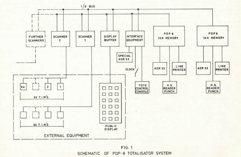
The tasks that the computer has to perform in the totalisator system are rather simple. Nevertheless, it is a true real time system where downtime cannot be tolerated, and it is not possible to switch to manual control if a catastrophic failure of the system occurs. For this reason the system uses two computers in twin configuration. This means both computers have the same status and are performing the same tasks. The input from the T.I.M.s goes into both computers and is identically processed. Should one of the computers fail , the other will continue operating without system degradation.
In a typical totalisator system following computer equipment is used:
- 2 X PDP-8 each with
- 16K memory
- ASR teletype
- HS Reader Punch
- Line Printer
Of the above options, item 4) is required only for convenience of rapid program loading. Item 5) is used for printing out all relevant race information during a short time interval of 3 minutes or less, between "Stop Betting" and "Start Betting" on the next race. This information is used for record purposes only, but is in most cases a government requirement.
The rest of the interface is constructed from DEC R and W series circuit modules. A block diagram of the entire system is shown on Fig. 1. Each T.I.M. scanner interfaces 64 ticket issuing machines. It tests each T.I.M. in turn for presence of a BID signal. When a BID signal is found, a SCAN signal is sent to corresponding T.I.M. which in turn causes the data from T.I.M., to be transmitted to scanner data register and the scanner to generate a service request signal to the computers. The computers then read in the data and start processing the bet. After the bet has been processed, the computers send either a CONFIRM or REJECT signal to the scanner. If the signals from both computers are in agreement, a corresponding signal is sent to the T.I.M., which in turn will drop off its BID signal. Fig. 2 shows the signal connections of a typical T.I.M..
Webmaster's note:
George Klemmer, who I have met and seen on a few social occasions, refers to the DEC R and W series circuit modules in the previous paragraph. The DEC R and W series circuit modules, refer to the PCBs (Printed Circuit Boards) with Red or White handles. The significance of these coloured handles has already been explained by Max Burnet above under the heading Information and Images from Max Burnet ex CEO Digital Equipment Corporation Australia. These PCBs can be seen in the image above, under the heading mentioned, titled Wooden Box of PDP8 Spare modules for rapid repair.
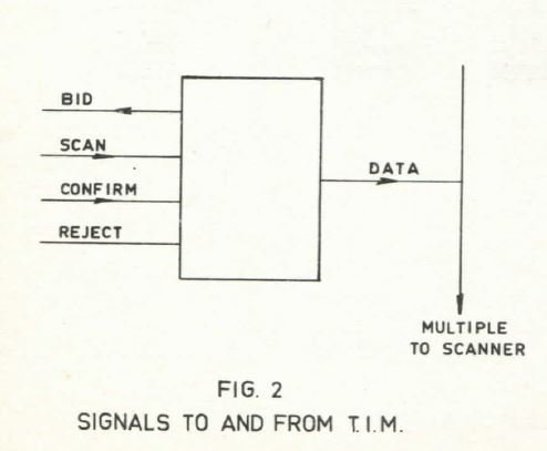
The display buffer provides means for storage of information to be displayed one field (up to 6 digits ) at a time. In addition to information, the field address is also stored in the buffer and decoded to select the field to be displayed. The display buffer is connected to output of either one or the other of computers by means of a manual switch.
The operators console provides the totalisator operator with a means of entering information into computers which is necessary to control the system during betting. Some pushbuttons on the console generate coded messages which cause the computers to take necessary action whereas others condition registers which establish lists of valid runners and results of the race. The commands entered via operators console (T.C.C.) as well as final dividends computed by the computers are logged on both ASR33-s. This provides a visual check that both computers are in fact in agreement. The clock signal is used to initiate display cycles and to keep the time of day which appears on all printouts.
The special Teletype is used on Australian race tracks for entering manually Totalisator Agency Board figures for the race. At present these totals are transmitted from TAB office to the race track by phone. It is hoped that in the future TAB will be able to transmit their figures directly into the computers via data link.
Webmaster's note:
As mentioned in the paragraph above, the manual entry of Off-Course figures over the phone into the local On-Course totalisator system at Harold Park, was the way it was when our new PDP11 system in Brisbane commenced operation in 1979. And yes, just as it was hoped in Harold Park as mentioned above, this did eventuate in an Inter-CPU link between the On-Course (ATL) and Off-Course (TAB) totalisator systems. In the interim however there was an intermediate step where the figures were entered manually however this was done through a remote terminal in the TAB Headquarters that was attached to the On-Course computer system, eliminating the need for a telephone conversation.
For reliability reasons the system uses redundant self-checking codes for T.I.M. data and public displays. There are also checks inbuilt into the system to ensure that both computers are in fact operating correctly. One of these, as explained earlier, is the requirement that identical signals from both computers are required to confirm a bet. There is also a special circuit provided in interface equipment which synchronizes the computers in the main program loop. (Fig. 3). Following seven instructions accomplish this task.
| FRED, | SET FLAG |
| SKIP ON AB SET |
| TRY AGAIN |
| CLEAR FLAG |
| TEST FOR AB |
| JMP INIT |
| TRY AGAIN |
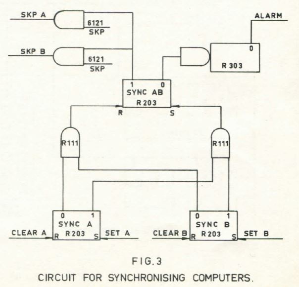
Every time the computers exit the check program the R303 is retriggered. Should one of the computers fail reaching the check program the one shot will time out and sound an alarm.
Over 15 systems as described above have been installed on race tracks throughout the World since 1968. They have functioned reliably in adverse conditions for the benefit and pleasure of racegoers.
Some tickets produced by this system from Chris Robertson
Chris Robertson provided the following Harold Park ticket images, of Win, Place, Double, Forecast and Quinella tickets, which were produced by the PDP8 totalisator system being described in this page. Chris purchased these tickets at Harold Park in 1973 and 1974.
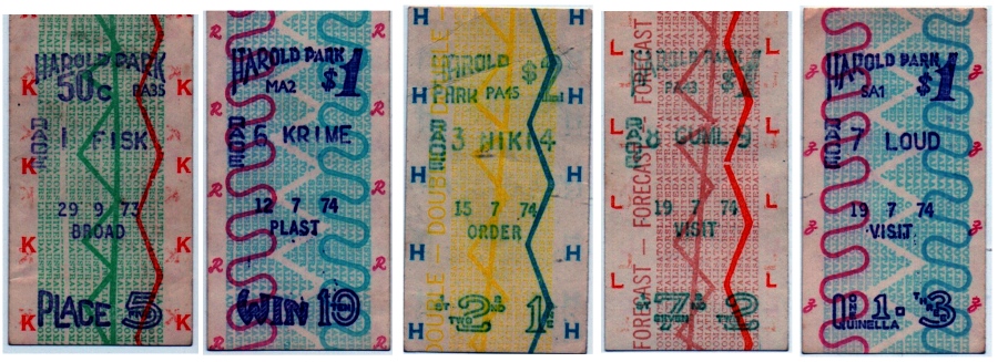
ATL PDP8 Tote System Tickets
Chris wrote the following about this tote at Harold Park as well as the equivalent ATL tote at Wentworth Park:
The tote at Harold Park and Wentworth Park was world's best. Instantaneous updates of Win,Place and Quinellas on electronic indicator boards was well in advance of what was available in Melbourne in the early 1970's. Even after the Melbourne race clubs computerised the tote in Spring 1974, the Harold Park and Wentworth Park totes were still offering a superior service in the display of betting odds.

Comments and suggestions welcome to
totehis@hotmail.com 
The Next page button below presents the first of four pages showing images of Julius totalisators, each of which were regarded as the largest totalisator in the world at their time, as well as information about these systems. The contract for the third of these large systems presented, was regarded as Australia's largest financial transaction with France at the time.
The Previous page button below presents the third and final page of the Memoires of an Operations Manager David Hamilton and Harold Park Trotting Track.