More after the image...
Click on the image to go back to the Photo Gallery
The White City Stadium system in London ended up with 320 terminals or TIMs (Ticket Issuing Machines). This Julius Tote system was one of the world's earliest on-line, large-scale, real-time, multi-user systems and was installed in 1933 when it became the largest totalisator in the world, stealing that title from the Julius Tote in Longchamps Paris. In my opinion, the world's first on-line, large-scale, real-time, multi-user system was the 1917 Julius Tote installed at Randwick Racecourse in Sydney. The prior Julius totes were all real time multi user systems.
More after the image...
Click on the image to go back to the Photo Gallery
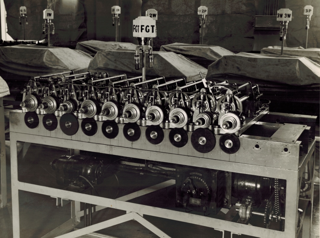
White city Stadium London - Front view of Forecast Grand Total showing alternative driving motors Left A.C. Geared motor Right heavy duty Series wound D.C. motor with speed regulator if required although the series characteristics of the D.C. motor give automatic speed regulation within very wide limits and we have not often to touch the hand regulator.
Note certain shafts have been speeded up in relation to the others. Due to very busy groups on those shafts. Gearing arranged so that choice of five ratios may be had for individual shafts.
This photo is of additional interest as it was taken with the adder already installed at White City Stadium and shows the motors installed underneath the surface of the mounting table. The drive motors are not shown on the adders photographed in the factory. I also find it interesting to see this adder accommodates two types of motors selected to utilise their specific characteristics and the note mentions the automatic speed regulation of the series wound D.C. motor. The speed regulator if required mentioned in the note, refers to the handle and lever that moves in an arc, which looks like a tram speed controller, under the tabletop, on the left of the right hand motor.
Of further interest is that in the note written on the back of the photo there is another note that mentions certain shafts being sped up. This is mentioned elsewhere in the Photo Gallery however here it adds the reason for it, that being very busy groups on those shafts.
These groups refer to the way the Ticket Issuing Machines are connected to the adders. TIMs are associated with a particular solenoid that activates an escapement mechanism in the adding shafts of the constituent shaft adders. These groups are time division multiplexed onto the solenoid by an electromechanical device called a scanner or distributor. The reference to busy groups means that machines attached to the solenoids in an adding shaft are more busy than the machines in other groups. This principle still applies today as some areas of the racetrack always have more betting activity than others. The constituent shaft adder assemblies are at the back of this complete adder and consequently are obscured from view in the image above. It is possible to glimpse part of one of these constituent shaft adder assemblies on the right hand side and at the rear of this complete adder in the image above. There are ten sub assemblies in the above complete adder each consisting of a storage screw assembly running for about two thirds of the depth of the complete adder from the front towards the rear, which then attaches to its associated constituent shaft adder that runs from the far end of the storage screw to the rear of the complete adder. There are two framework support rods per sub assembly the first runs along the top of each of the ten storage screw assemblies and the second on top of each associated constituent shaft adder assembly or what are often called adding units. The ten storage screw framework support rods are clearly visible in the image above, running parallel to each other from the front towards the rear of the complete adder assembly and are the highest part of the storage screw assemblies. A second framework support rod then runs at a lower level than the first the final one third of the depth of the complete adder to the back of the adder. Part of the right hand one of these lower framework support rods can be seen at the rear of the complete adder in the image above. Below this lower support rod is the adding shaft for this adding unit, with its escapement wheels, epicyclic gears and solenoids that are activated by impulses from the TIMs resulting in the release of the associated escapement mechanisms to allow adding shaft rotation to record the transactions. This visible adding shaft is one of ten along the back of this adder. The ten constituent adders can easily be seen in the plan view image of this adder seen below. They are the ten assemblies across the back of the adder seen at the top of the plan view image, two smaller ones on the left and eight larger ones on the right. The right hand eight have visible cabling attached to them.
Now to the sped up shafts. The busy groups result in the associated adding unit having the storage screw move quickly. The storage screw is a mechanical form of memory and stores transactions that are recorded as angular displacement with rapidly accelerating angular motion. The heavier, slower to accelerate equipment needs more time to accelerate and during this period the transactions need to be stored for later retrieval. The storage screw bodies, which George Julius described as nuts, can be seen as tubular devices that run from the associated adding shafts at the back of the complete adder to the front of the adder and underneath the associated higher framework support rods previously mentioned in the image above. The Storage Screws are obvious in the plan view of the adder shown below, the ten tubular devices connecting the constituent adders seen across the top part of the image which is the back of the GT Adder to the cogs seen across the bottom part of the image at the front of the adder. The storage screws near the centre of the adder are somewhat obscured by the top framework support rods. These storage screws are described in the text associated with other images in the Photo Gallery. The reading of the storage screw must be sped up on the busy groups to ensure the associated storage screw does not reach its storage limit otherwise transactions will be lost. In electronics this would be considered a buffer overrun error or a buffer overflow error. I presume that all storage screw shafts are not configured to run at flank speed as the greater the velocity, the greater the stresses the equipment is subjected to. I had an epiphany regarding a similar comment about some shafts being sped up in the Brough Park section of the Photo Gallery. The result is that I now know it is easy to see which shafts are sped up. In the adder image above it is the shafts in the third and ninth adding units counting from the left. This is easy to see. The large black cogs mounted on the front of the table are the main drive cogs and the large silver shiny cogs above that mesh with them, provide the drive for their respective storage screws and adding shafts. As can be seen the third and the ninth pairs of cogs have a larger black drive cog and a smaller driven silvery cog than the others, resulting in higher angular velocity of the tubular bodies or "nuts" of the storage screw shafts respectively associated with them. This expedites the return of the internal grub like screw driven into the tube by the respective adding shafts back to its rest position.
A Plan View of the same adder
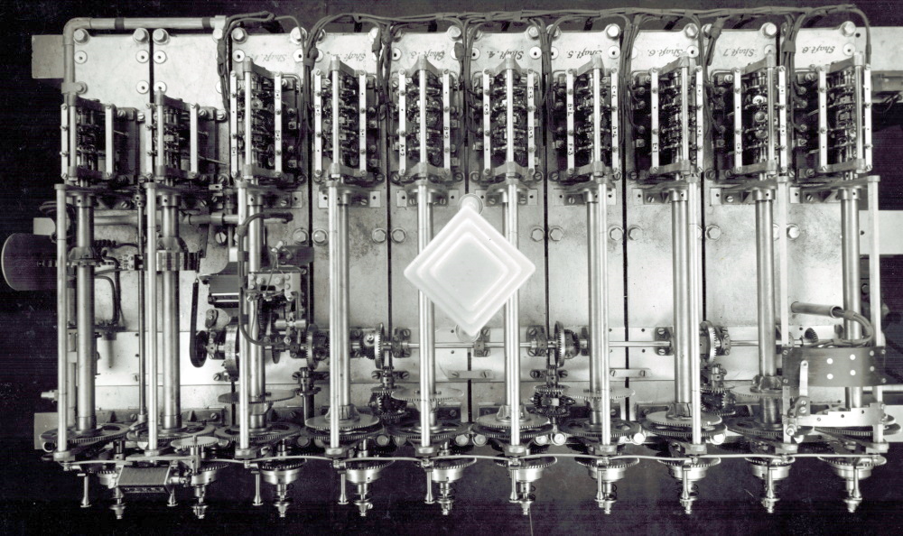
On the back of the plan view photograph shown in the image above, which is a top down view of the adder at the top of this page, the note reads:
White City LondonPlan view of Forecast Grand Total
Number of shafts increased and fewer (4) escapements put on each in order to keep speeds down.
Field betting shaft is No 8. Four way switch obscures view of cone of gears and Tumbler although gear lever may be seen.
By increasing the number of shafts, the maximum rotational velocity of the storage screws can be reduced. The way this is achieved, as the note implies is by reducing the number of escapements in the constituent shaft adders or what have also been called adding units, seen across the back of this complete GT adder and replacing them on an additional shaft or shafts. The teeth on the four escapement wheels, mentioned in the note, in each of the right hand eight constituent adders, can be seen in this plan view image. They are mounted at right angles to their respective storage screws and are within their right hand eight constituent adder frames. There is identification text etched on the GT Adder frame that is upside down in this view of the adder, that can be seen within the cable loom loops at the top of the photo, above each constituent adder, identifying the respective adders. It reads from far right to left Shaft 8 Shaft 7 Shaft 6 Shaft 5 Shaft 4 Shaft 3 Shaft 2 Shaft 1. As the value of bets are recorded as rotational displacement of adding shaft segments associated with their escapement wheels within the constituent adders, the fewer escapement wheels there are on an adding shaft, the less rotational displacement there is of the output shaft of each constituent adder, which is the sum total of all the rotation of all the escapement wheels in a constituent adder. The output shaft of each of the constituent adders then drives its respective storage screw. It would appear that this design to keep the speeds down was effective judging by the note on the back of the photo shown at the top of this page stating and we have not often to touch the hand regulator.
The note on the back of the plan view image identifies the Field betting shaft as number 8. A Field bet for the Forecast pool is one that covers every possible combination of winning runners. As identified in the previous paragraph, shaft number 8 is the first shaft on the right hand side of the whole adder. The bottom part of this shaft partly lies beneath the right hand side of the archways associated with the four way switch, also mentioned in the note on the back of the plan view photograph. There are two arches associated with the four way switch, the lower selector handle arch and the upper moving contactor arm arch in the plan view image. Both arches can also be seen in the image at the top of this page where the curvature of the archways is clearer. Six metallic shiny circular contacts of the four way switch can clearly be seen on the contactor arm arch in the plan view image. The selector handle arch is a metal one and functions as a guide for the selector handle which moves the associated contactor arm. The selector handle can best be seen in the top image protruding above the adder about thirty degrees left of vertical from the left hand side of the selector handle arch. This guide has what looks like steps clearly visible in the plan view image of the adder, however they are not steps as they exist in the horizontal plane and do not rise. If you move the handle to the right it will move to the first step and stop there. This is the second position for the switch. To select the third position the handle is pushed towards the rear of the adder to pass the first step and that then allows it to be moved to the right to the third position where it hits the second step. This is repeated, push rearward to get past the second step and then move right till it hits the final step at its fourth and final position. The handle seems to have a spring loaded locating pin that engages in one of the holes in the archway guide at each of the step stops, three of these holes are clearly visible in the plan view. To move the handle, presumably you lift the top of the handle, disengaging the locating pin from its hole, and moving the handle to its desired position then releasing the handle allowing the pin to engage the new hole locking the handle in its new position on the metal arch plate. The second more distant arch in the photo at the top of this page, which is the upper one in the Plan View image, looks like it is made of Bakelite in the plan view, or some other insulating material. I will refer to this as the Bakelite arch. It contains four pairs of metal studs aligned with the four resting positions of the handle that act as contacts. There is a metal arm attached to the handle that stretches over these studs on the Bakelite arch. At each step position as the handle moves to the right, the studs are located further towards the rear of the adder from the perspective of the plan view image of the complete adder, accommodating the handles movement towards the rear of the adder when it mounts the next step. I presume the metallic projection that contacts the studs on the Bakelite arch electrically shorts the selected pair of stud contacts together, closing an electrical circuit. Presumably, one pair of studs are not visible as they are currently underneath the contactor arm in its current position.
In a high resolution copy of the plan view image, I can see a drive shaft extending right from underneath Shaft 8's base plate. The shaft can be seen immediately below and on the right hand side of the bakelite arch with the shaft extending off the right hand side of the image above. Not visible in the image above as it has been trimmed, in the high resolution copy I can see the drive shaft extends right a little further than in the image above and has a sprocket wheel on the right hand end of it that has a chain attached to it, driven by the electric motor under the bench. The lower part of this chain can be seen in the image at the top of this page, below the top of the mounting table on the right hand side and to the right of the right hand motor, almost parallel to the right hand leg of the table. At the bottom, the chain is engaged around a small sprocket wheel mounted on a shaft that has a larger sprocket wheel to the left, with another chain around it that comes from the motor. This shaft with the two sprocket wheels on it, has large bearings at both ends of it. The bearing casings both have an oil spout protruding up and somewhat right with a filler cap on top them. The right hand cap is clearly visible like a large shiny coin on the right hand side of the right hand leg of the table above the height of the two sprocket wheel shaft. To me it seems the amount of bearing oil containable in the rather large looking casing reservoir means this motor did a lot of heavy work. The chain on the small sprocket wheel can be seen heading up to the sprocket wheel at the right hand end of the previously described shaft disappearing off the right hand end of the plan view image. What can be seen of this in the plan view image above, are two parallel black lines even though it is on a dark background, spanning between the right hand edge of the image and the right hand end of the bakelite arch at an angle of about 55 degrees from vertical. These black lines are the up-going and down-going sides of the chain mentioned. I presume the drive shaft described drives the large black cogs seen across the front of the table in the image at the top of this page. Presumably, there are ten worm gears along this shaft that drive ten shafts at right angles to this shaft that respectively turn the ten black cogs mounted on the front of the table.
In the plan view, a cable conduit can be seen behind the Bakelite arch with cables coming out of the top of it and disappearing under the arch, presumably to be terminated on the back of the studs in the Bakelite arch that the selector mechanism shorts out. As the bottom end of the conduit descends through one of the GT Adder's base plates, I cannot determine where these cables go and consequently cannot determine anything definite about what the switch does. The note extract Four way switch obscures view of cone of gears and Tumbler although gear lever may be seen, is tantalising to say the least, as I am sure a view of the cone of gears and the tumbler would be very revealing. The best definition of Tumbler Gear I have read is from SFriedberg in Oregon in a practical machinist forum any of various reversing or speed-changing gears used especially in modern machine tools that have one or more idle wheels journaled in a swinging frame moved and clamped in position by the operator. I was aware of the reversing capability of tumbler gears but I can see no application for that in this GT Adder but speed changing gears is what we do have here. Also sfriedberg's moved and clamped in position by the operator is what the handle and the selector handle arch in this GT Adder are all about. Sfriedberg adds It's the swinging frame aspect that gives rise to the "tumbler" nomenclature. The handle of the feed select lever, of course, being the end of the swinging frame. The handle in the image at the top of this page can be seen extending downwards to its fulcrum somewhere below the level of the storage screws. The large cogs mounted above, behind and to the left of each of the shiny cogs across the front of the GT Adder in the image at the top of this page and are centred on the tubular body of their respective storage screws are the storage screw drive cogs. Between and behind the two right hand storage screw drive cogs near the bottom of where the gear lever handle seems to be descending to, are two more smaller shiny cogs a smaller one in front of another larger one behind. Is this part of the cone of gears? As I cannot see these gears in the plan view image and as the note on the back of the plan view image states Four way switch obscures view of cone of gears and Tumbler, this could well be part of the cone of gears. Alas alack, not enough information!
Going back to the note on the back of the plan view photograph of this adder quoted above, it refers to the handle on this four way switch as a gear lever in the words although gear lever may be seen. Consequently I presume there are two possibilities. First, the four way switch has something to do with changing gears electrically, or second the gear lever changes gears mechanically somewhere out of sight of any of the photos, as well as operate the 4 way switch which may drive some selected gear indicator. Additionally, I have been wondering about the sentence Gearing arranged so that choice of five ratios may be had for individual shafts, extracted from the note on the back of the image shown at the top of this page. As previously noted gearing can be set in the manufacture of these complete adders by changing the ratios of the diameter of the large black Drive Cogs across the front of the adder table in the image at the top of this page, and the diameter of the Bright Shiny Cogs that they respectively mesh with. I can see no sign of any operationally selectable gearing for individual storage screws/shafts as quoted. It seems to me that the cone of gears would change the gearing for all the shafts. Perhaps the four way switch has something to do with this. Additionally I am not sure how the four way switch would provide five ratios unless the switch has an off position that defaults to the fifth ratio. There is a limit to what can be determined from close examination of photographs that are almost nine decades old at the time I am writing these additional details to this page in September 2022. Again, oh how I wish for a view of the Cone of gears and the Tumbler.
The two shafts on the left hand side of the GT Adder as seen in the plan view image, that have shafts one through eight on their right, have no shaft numbers allocated to them. So far as I can tell from the plan view image, the second shaft from the left hand end is what has been called a Tens Shaft. If you are interested in this, click on the image at the top of this page to load the photo gallery index, then have a look at the second image in the Brough Park Newcastle Upon Tyne 1936 section of the Photo Gallery, with the associated description starting with the words This image shows the top view of the adder in the previous image... The tens shaft handles bets of a value ten times the base value bet, so at White City this is probably a ten shilling shaft. It can be driven by ten shilling TIMs and receives the carry from the units shafts. Most TIMs on the track sell one shilling bets or multiples thereof. This tens shaft drives a small mechanical counter seen in both images mounted above and near the left hand end of the row of ten bright shiny cogs along the front of the Adder. From a high resolution version of the image at the top of this page, I can see this five digit display counter at the time the photo was taken reads 00036. To read this adder the 00036 are the most significant digits of the grand total. To the right of this front counter and hidden from view in the image at the top of this page but visible in the plan view, seen immediately to the left of Shaft 1, and about a third of the way up the shaft is a shiny wheel parallel with Shaft 1. It is not evident at this resolution however from the high resolution version I can see this is a drum-wheel counter with a pointer to the digits zero through nine marked on the perimeter of the drum-wheel. This triangular pointer is visible in the plan view image above protruding left from underneath the top framework support rod of Shaft 1 that is above and parallel to Shaft 1, pointing to the drum-wheel near to its highest point. The digit the triangular pointer is pointing to is the least significant digit of the grand total. In a high resolution version of the plan view image, the pointer is pointing to five so the grand total figure is 000365 or 365 shillings or whatever the base unit of investment was at the time. I do not think this is an actual figure after a race but a result of testing. These systems were rigorously tested before going live after installation and received significant testing prior to each race meeting for the duration of its service life. To see a detailed view of this drum counter wheel, there are three of them visible in the plan view of the Brough Park 3-3 shaft GT adder, which is the same image previously mentioned in this paragraph, although they are mounted 90 degrees displaced from this one. The difference in mounting is due to this one being mounted on the left hand end of a horizontal shaft and the ones in the Brough Park GT Adder are each mounted on vertical shafts. The first shaft on the left hand side of the GT Adder in the plan view image above is a Tens Transfer Shaft with its cam wheel and tens transfer contactor as described in the Brough Park GT adder plan view image file mentioned. This drives the tens solenoid in the Forecast GT part of a public display indicator and most probably for this GT adder at White City, it would drive multiple indicators to provide coverage for the far greater number of punters attending meetings.
The Plan View image of this adder presents a good view of something that ties the individual constituent shaft adders and their associated storage screws together. In that image above, just below the bottom corner of the diamond shaped lamp in the centre of the adder, what looks like a horizontal shaft can be seen extending from the right hand side of the adder and extending horizontally left to a position between Shaft 1 and the Tens Shaft. This shaft is actually several shaft segments that successively sum the totals from right to left, of the eight storage screw unit shafts from Shaft 8 through to Shaft 1. Mounted on this shaft near the right hand end of it, a bevel gear can be seen with the bottom part of it obscured by the top of the Bakelite arch. The driving cog for this bevel gear is also obscured by the Bakelite arch, however the hidden mechanism will transfer the bet transactions stored on the right hand storage screw/shaft and associated constituent shaft adder to the horizontal shaft. As previously mentioned, this right hand storage screw shaft is the Field betting shaft and the hidden mechanism mentioned will have everything to do with the cone of gears and Tumbler and gear lever mentioned in the note on the back of the plan view photograph. The rotation of the bevel gear is transmitted to the left under the second shaft from the right that is shaft 7 and continues to the left to a position near the right hand side of shaft 6, where it is attached to an epicyclic gear arrangement with one of the four largest bevel gears on this horizontal shaft. What looks like a horizontal shaft actually consists of five shaft segments, each successive segment having greater angular displacement than its neighbour to the right, if all shafts are active as is the case during heavy betting periods, as the epicyclic gears sum the successive rotation of the storage screws/shafts to the horizontal shaft segments. This epicyclic gear that appears to be mounted on the horizontal shaft has two inputs, the right hand shaft segment and the output of a second epicyclic gear and has one output the left hand horizontal shaft segment. The output of a second epicyclic gear mounted perpendicular to and below the horizontal shaft drives the larger bevel gear mentioned, that is on the right hand side of the epicyclic gear on the horizontal shaft, with its planetary gears partially obscured to the left of it. The second epicyclic gear has two inputs. Mounted on the second shaft from the right, shaft 7, is a large shiny cog which can be seen slightly below the position of the bottom of the Bakelite arch on its left hand side, as it appears in the photo. The bottom left part of the arch obscures part of the right hand side of this large cog as does the lower part of the Shaft 7 framework support rod. The left hand side of this cog can be seen engaged with a much smaller cog closer to the base of the adder, that is mounted on the top side of the second epicyclic gear. Now looking at the third shaft from the right, shaft 6, it too has the same type of large shiny cog mounted on it, only lower down the shaft as seen in the photo, closer to the front of the whole adder. The right hand side of this cog, near the base of the whole adder, is engaged with another smaller cog that is mounted on the bottom part of the second epicyclic gear. So this second epicyclic gear adds the rotation of shaft 7 to the rotation of shaft 6 and transfers the output to the large bevel gear previously mentioned that is on the right hand side of the first epicyclic gear, via a small bevel gear at the top of the second epicyclic gear output shaft. This small bevel gear is driven by the planetary bevel gears of the second epicyclic gear assembly and one of the two planetary gears is clearly visible between the two input cogs which are the smaller cogs mentioned at the top and bottom of the second epicyclic gear. Both planetary bevel gears track around bevel gears cut into the inside sides of the two input cogs. The first epicyclic gear now adds the summed rotation of the second epicyclic gear to the rotation of the right hand shaft segment of the horizontal shaft and transfers the summed rotation to the next left hand segment of the horizontal shaft. In other words the rotation of the horizontal shaft segment visible between shaft 6 and shaft 5, third and fourth shafts from the right, which is driven by the first epicyclic gear, has an angular displacement equal to the sum of the angular displacements of the first three shafts of the storage screws from the right hand side. From now on I will refer to the storage screw shafts by their marking etched on the frame as previously described, which are decreasing numbers when moving to the left.
Now looking at the horizontal shaft between shafts 5 and 4 you can see a repetition of what we have seen between shafts 7 and 6 except this is a better view of the epicyclic gears as they are not partially obscured. If you zoom in on the epicyclic gears you will get a better view of the constituent bevel gears. As before, there is a third epicyclic gear, counterpart to the first, that is mounted on the horizontal shaft segments and a fourth epicyclic gear, counterpart to the second, that is perpendicular to the horizontal shaft segments. The two shiny cogs one on shaft 4 mounted lower and the other on shaft 5 higher, are easier to see than the ones previously mentioned on shafts 6 and 7. By the same reasoning presented in the previous paragraph, the rotation of the horizontal shaft segment visible between shafts 4 and 3 and to the left of the third epicyclic gear, has an angular displacement equal to the sum of the angular displacements of the first five shafts of the storage screws from the right hand side. On the right hand side of the large bevel gear between shafts 4 and 5 an assembly can be seen attached to it. This contains the two planetary bevel gears of the epicyclic gear arrangement, their axis of rotation being at right angles to the horizontal shaft. On the right hand side of the two bevel gears mounted on the perpendicular axis, a small bevel gear on the horizontal shaft segment coming from the first epicyclic gear mentioned, is engaged with the two perpendicular bevel gears 180 degrees apart from each other as they share the same axis of rotation and are free wheeling on their spindles and have opposing directions of rotation. In other words you can see whole workings of epicyclic gear three. This is very clear in a high resolution version of this photograph. It is the rotation of this pair of bevel gears on the perpendicular axis around the horizontal shaft that is the result of the summing action and this rotation around the horizontal shaft drives the shaft segment on the left of this epicyclic gear assembly number three. You may have noticed that this large bevel gear, which is part of the epicyclic gear mounted on the horizontal shaft, is the opposite way around to the one prior. In other words this large bevel gear between shafts 5 and 4, that is part of an epicyclic gear arrangement, has its planetary gears on the right side of it and the large bevel gear between shafts 3 and 2 has its planetary gears, on the left side of it. Similarly, the large bevel gear between shafts 7 and 6 has its planetary gears on the left side of it, those gears being partially obscured by shaft 6 and its associated top framework support rod, and this is the opposite way around to the one between shafts 5 and 4. Additionally the large bevel gear between shafts 5 and 4 has its bevel gear teeth on the left hand side of it and the one between shafts 7 and 6 has its bevel gear teeth on the right hand side of it, which is the same way around as the large bevel gear between shafts 3 and 2. I think this reversal is due to the epicyclic gear arrangement reversing the direction of rotation of the horizontal shaft segments. This horizontal shaft is similar to the adding shafts in the constituent shaft adders. I think the large bevel gears in this rendition of an adding shaft are analogous to the escapement wheels in the constituent shaft adders. In the shaft adders I have seen, that are similar to the constituent adders in this complete adder, the adjacent escapement wheels rotate in opposite directions. Similarly on this horizontal adding shaft in this complete GT Adder, every adjacent epicyclic gear is reversed to its predecessor to accommodate this reversal of the direction of rotation of the horizontal shaft segments. The direction of rotation is only significant to it being appropriate to any downstream equipment, it is the angular displacement of the shaft segment that is important.
The horizontal shaft segment passing under shaft 4 continues underneath shaft 3 and in between this shaft and shaft 2 there is another pair of epicyclic gears. Similar to the ones so far described, the epicyclic gear perpendicular to the horizontal shaft sums the rotation of shafts 2 and 3. The epicyclic gear mounted on the horizontal shaft adds the rotation from the perpendicularly mounted epicyclic gear to that of the first five storage screws on the right hand side. The output of the horizontally mounted epicyclic gear drives the horizontal shaft segment to the left and it disappears from view under shaft 2.
This leftward extending horizontal adding shaft segment remains hidden from view by shaft 2 and the associated framework support rod seen above shaft 2. To the left of the support rod and associated shaft 2, another large bevel gear can be seen on the horizontal shaft. At the bottom end of this large bevel gear as seen in the plan view image, a much smaller bevel gear can be seen engaged with the left hand side of it and this smaller bevel gear is attached on the top of a perpendicular shaft secured to a rod seen running down the image towards the front of the whole adder where it is attached to the front mounting plate of shaft 2. The large bevel gear is a counterpart to the three prior large bevel gears mounted on the horizontal shaft so far described. The perpendicular rod supporting the bottom of the short perpendicular shaft replaces the perpendicular epicyclic gears so far described, as Shaft 1 is the last of the 8 Unit Shafts and no additional summing is required with the next adjacent shaft to the left. At the bottom of this short perpendicular shaft as seen in the image, slightly below the shaft support bracket seen slightly below the small bevel gear securing the shaft housing to the base of the adder, a small cog can be seen engaged with the large cog mounted on Shaft 1. So Shaft1 drives the small cog on the perpendicular shaft that drives the associated small bevel gear above it, which drives the large bevel gear on the horizontal shaft, which is part of an epicyclic gear with its planetary gears on the right hand side of it. This epicyclic gear sums the rotation of shaft 1 with the total rotation of the seven shafts to the right. The left hand segment of the horizontal shaft to the left of the large bevel gear then extends underneath Shaft 1 terminating in a mini drum counter wheel at the end of the horizontal shaft segments as previously described. I will add a bit more about the drum counter wheel. The mini drum counter wheel is mounted on the horizontal shaft segment seen to the left of and parallel to the framework support rod above Shaft 1, and is centred on and perpendicular to the final horizontal shaft segment. This drum has markings on it 0 through 9 repeated possibly three times around the circumference so far as I can tell and rotates with the final horizontal shaft segment, although the markings are not clear in the plan view image above. In a high resolution copy of the plan view image above, I can see 9 just in view at the top of the counter wheel followed by 0 1 2 3 4 5 6 7 and 8 barely in view at the bottom end. A pointer previously described can be seen extending left from and attached to the framework support rod mounted above and running parallel to Shaft 1. This pointer is pointing to the number 5 on the drum counter. Even at the resolution of the image above, if you zoom in on this pointer you can just make out the 5 it is pointing to, as well as 4 and 3 above with 6 and 7 below. This drum wheel counter provides the least significant digit of the grand total as previously described. The 5 most significant digits are provided by the small mechanical counter previously described so the Forecast Pool grand total consists of 6 digits in the White City system with the upper limit being 999,999 units, which probably were shillings, based on the fact that this system was installed in London in the United Kingdom and at the time the currency was Pounds Shillings and Pence.
The substantial mechanism around shaft 1, seen above the horizontal shaft in the plan view image, is called a Chaser. Following is an extract from a note on the back of another image of a GT Adder in the factory, destined for Brough Park in Newcastle Upon Tyne, Note "chasers" for transferring the odd units to drum indicators at close of betting. The photo from which the quote was extracted, can be seen by clicking on the image at the top of this page, then scrolling down past the heading in the photo gallery index Brough Park Newcastle Upon Tyne 1936 and then selecting the image thumbnail below, with the associated descriptive text starting with This image shows the top view of the adder in the previous image... That GT adder for Brough Park handles three different pools and consequently has a chaser for each pool, however the GT adder in the images above belonged to the White City system, which was a much larger system and consequently handled one pool only. Additionally, that is why this GT Adder has eight Units Shafts just for the Forecast Pool and the Brough Park one only has two per pool. This plan view image, provides the best view of a Chaser I have seen. However even with a high resolution copy of this plan view image, the chaser's mechanics are too complex to hazard a guess as to how it works. It is further complicated by the fact that there is an electrical element to the Chaser. The public Drum Indicator units did have solenoids and associated escapement mechanisms, the solenoids requiring electricity to activate them and the associated escapement wheels then mechanically drove the drum counter display wheels. A four digit version of one of these Drum Indicator units can be seen by clicking on the image at the top of this page then scrolling down past the heading in the photo gallery index Brough Park Newcastle Upon Tyne 1936 and then selecting the image below with the associated descriptive text starting with This photograph shows a Drum Indicator unit. The Chaser in this GT Adder, drives the least significant digit via the units solenoid of a similar Drum Indicator Unit, only larger. As previously mentioned, the Drum Indicator Unit tens solenoid is driven by the tens transfer contactor associated with the Tens Shaft in this GT Adder. The grand total public display unit at White City would have had a 6 digit display as previously mentioned and I have included the four digit indicator unit in the photo gallery as an example of these units as I have no other photo of these display units. It is possible that the four digit drum indicator unit was a runner total indicator as runner totals are obviously smaller than the grand totals. One final comment about the Chaser, mounted on the final horizontal shaft segment, just to the right of Shaft 1 a cog can be seen. This transfers the rotation of this final horizontal shaft segment on its way to the mini drum counter wheel to a cog in the Chaser mechanism.
Returning to the electrical element of the Chaser in the plan view image, an electrical cable, possibly two core, can be seen rising out of the lower centre of the Chaser mechanism between shafts 1 and 2. In a high resolution image, each of the two cores seem to be secured under what looks like its own small hexagonal headed screw each sitting on top of its own associated strip of metal side by side above the horizontal shaft, extending downwards towards the base of the whole adder and towards the rear of the adder, or up as seen in the image. The cable runs left towards Shaft 1 and then turns upwards as seen in the image, where it is bound to the top of the framework support rod above Shaft 1. The cables are secured to the top framework support rod with what looks like tape at four points as it runs upwards. A second cable looking like the first, joins this first one from the right hand side, about half way up its upward run on the top framework support rod. The two cables travel further up the framework support rod then turn right and head towards Shaft 2 some distance and then drop towards the base of the GT Adder where they enter a conduit clearly visible extending left heading in the opposite direction underneath Shaft 1 and the last two shafts on the left hand side of the whole GT Adder. I think at least one of these cables will be destined for the public display indicator outside of this adder and outside of the machine room, to a public area where the punters can see it.
Regarding the mention of transferring the odd units to drum indicators at close of betting in the quote extracted from a note on the back of a Brough Park GT Adder previously mentioned, I have been wondering why the odd units on the indicator are only shown at close of betting. The tens of units are continuously transmitted to the drum indicators by the tens transfer shaft, as the bet transactions occur throughout the race betting period. I have read and heard that when these systems were in operation, the unit odds wheels in the indicator would spin so rapidly that it was just a blur anyway, and this would particularly be the case for a grand total display as opposed to the lesser investment on each of the individual runners being displayed in the indicator. Additionally, the systems where the units are being displayed and tend to be blurry during busy periods are probably on smaller racecourses where the betting is not so rapid and constant. White city was a large tote system and hence it was probably pointless having unit wheels spinning at flank speed in the indicators for long periods of time. I wonder what happens when there is a lull in betting however. Perhaps the worst case scenario of nine shillings, if shillings are the unit of investment, in the pool grand total is not worth worrying about until the race closes for betting and the dividends will soon be calculated.
The second shaft from the left, on the left hand side of Shaft 1 is not numbered. As previously mentioned, this is the Tens Shaft. Following is a quote extracted from a note on the back of the photograph seen in the first image of the Brough Park GT adder in the Brough Park section of this Photo Gallery, Grand Totals have two units shafts (each 3 escapements) and one tens shaft to keep speeds down as at White City. This tens shaft is the one mentioned in this note extract. As mentioned, White City was a large Julius Tote system. Unlike the Brough Park system this GT adder has 8 unit shafts to keep speeds down unlike the two mentioned in the Bough Park note. Being a large system, even with eight unit shafts, to accommodate the large number of TIMs, each constituent shaft adder has four escapements not the three mentioned for Brough Park.
The Tens Shaft has a small constituent shaft adder at the top of its shaft in comparison to those of shafts 1 through 8. This constituent shaft adder has one epicyclic gear with two inputs. In comparison there are four inputs using escapement wheels in each of the eight constituent shaft adders above each of the eight shafts on the right hand side of this whole GT Adder. These escapement wheels are clearly visible in the eight four input constituent shaft adders. The constituent shaft adder above the Tens Shaft, will receive the carry from the total of rotation of shafts 1 through 8. In between the Tens Shaft and Shaft 1, slightly below the bottom end of their constituent shaft adders in the plan view image, a shaft can be seen rising up the image on the base of the adder, from the top left corner of the Chaser Mechanism. In case you are having difficulty locating this shaft, it is near the left hand side of the top framework support rod of Shaft 1 and parallel to it. This rising shaft passes underneath a conduit that crosses at right angles from left to right. I think this rising shaft is the Carry Shaft from the Shafts 1 through 8. The conduit the carry shaft passes under is the same conduit mentioned in the paragraph describing the Chaser's cables. Again in a high resolution image I can see a lower part of this rod and it disappears below the units drum wheel counter. As the drum wheel counter's rotation is equal to the sum of the total rotation from Shafts 1 through 8, I presume there is a mechanism below the drum wheel that rotates this carry shaft once the units counter counts 10, and this rotation of the Carry Shaft trips one of the escapement mechanisms in the constituent shaft adder at the top of the tens storage screw shaft. Again in the high resolution copy of the plan view image, I can see the top end of this Carry Shaft has an arm extending upwards, not in reference to the image, but away from the base of the adder towards the viewer in the depth dimension. This is starting to become difficult to make out what the rest of the mechanism is. The upward extending arm looks like it could be analogous to a con rod in a reciprocating engine. I think there might be a crankpin journal attached to the top of the Carry Shaft with reference to the image. The bottom of the upward extending arm could be connected to this journal analogous to the big end in a reciprocating engine only in this case this end is not being driven but is driving. At the top end of this arm there is another journal supported between two arms projecting from a bracket on the left. This journal is similar to the small end on a reciprocating engine conrod except this end is driven from the big end not a piston. The end result, if this is correct, is that the rotation of the Carry Shaft is causing reciprocating motion at the top of the arm mentioned. On the left hand side of the bracket, in the high resolution image, in a dark part of the image making it impossible to see any details I think I can see an activating rod attached that travels left towards the bottom of the constituent shaft adder as seen in the image, where it disappears from view. I expect this activating rod is the activator for the lower escapement wheel in this Tens Shaft constituent Shaft Adder. The bracket with the journal, that joins the arm on the right to the rod on the left can be seen in the plan view image above as a small squat comparatively shiny rectangle part surrounded by darker areas seen above the lateral conduit mentioned that crosses the carry shaft with respect to the image, between the bottom right hand end of the tens constituent adder and the bottom left hand end of the Shaft 1 constituent adder. There is a smaller dark rectangle within and on the right hand side of the shiny one. This dark rectangle is where the arms project out to the right to support the small end journal. It is unclear what activates the second or upper escapement in the constituent shaft adder at the top of the tens shaft. It would be logical for a group of ten shilling TIMs to activate this however I cannot see any solenoid associated with this escapement wheel combined with the fact that I cannot see any electrical cabling associated with this constituent shaft adder so I do not know what activates this second escapement wheel. This only leaves one remaining storage screw shaft, the one on the far left of this complete adder. I think this is the Tens Transfer Shaft used for driving the Forecast Grand Total display unit in a remote public indicator. A sizeable cam wheel can be seen mounted on this Tens Transfer Shaft about a quarter of the way down. The cam wheel has a roller coaster like perimeter on it and a cam follower on the perimeter operates a switch that closes when the cam follower is going over a peak and opens when the cam follower travels through a valley, or vice versa as this is indeterminable from the image. Cables associated with this switch can be seen in the vicinity of the cam wheel. This switch is called a Tens Transfer Contactor. This Tens Transfer Shaft has a similar activation shaft to the Carry Shaft in the Tens Shaft assembly, running parallel to and close to the left hand side of the second vertical framework support rod from the left hand side. The activation mechanism for this Activation Shaft that I will call the 10X2 Activation Shaft can be seen by zooming in on the bottom end of this shaft. It has an arm attached to the end of it seen rising, in the depth dimension, from the rod and near to the face of the large cog attached to the bottom end of the Tens Storage Screw Shaft. This rising arm has a bend towards the right at the near end of it. There are two notches separated by 180 degrees on the surface of the large cog mentioned on the Tens Shaft. These notches are clearly visible in the plan view image by zooming in on the large cog at the bottom end of the Tens shaft. One notch is near the tip of the activating arm with the bend at the end of it and the other is on the same inside surface of this cog separated by 180 degrees from the first. As the Tens cog rotates each notch in turn comes to the arc section of the arm and lifts the arm up as the notch rides over the outer perimeter of the arm and eventually disengages as the notch moves away from the arm. In other words the tens shaft large cog lifts this activating arm twice per revolution of the tens shaft leading to the name 10X2 Activation Shaft. The other end of this 10X2 Activation Shaft, probably activates the lower escapement wheel of the left hand constituent shaft adder as described previously for the Tens Shaft.
Before proceeding I wish to convey that I am unfamiliar with the epicyclic gear assembly utilising the large bevel gear wheels. Additionally, I know of no one who even remembers or have ever heard of this type of Julius Tote large bevel gear epicyclic gear arrangement, never mind knowing something about them. At least I knew people who had worked on the epicyclic gears as seen in the eight constituent shaft adders in this GT adder and in a few cases befriended mechanical engineers who had not worked on them but have been so fascinated by these systems and have even dismantled some to determine exactly how they work. So far as I am concerned, I have repeatedly indicated in this website that I never worked on any Julius tote equipment but have learnt a lot from talking to people familiar with these systems and reading some of George Julius' terse descriptions and studied many Julius Totes as well as having my own shaft adders which I saved from being discarded. I have been told that George's technical descriptions were deliberately terse as he was concerned about leaking design information despite protection by patents. I make a distinction here that there is a difference between functionality and mechanical design that implements that functionality. Up to this point I have primarily dealt with functionality that I am as certain about the accuracy of, as someone who has not worked on these systems can possibly be in describing this GT Adder. At least with the epicyclic gears as seen in the constituent adders, I have other similar adders in my possession that I can manually wind up and trip the escapement wheels manually to observe their working. I only know of one person who worked with the White City Julius tote in London who I met when he was on holiday from the UK in Australia, however he worked on the operational side of the system and was not mechanically minded. In conclusion, I have agonised over whether the axle mount block for the planetary gears that seems to be attached to the large bevel gear can rotate around the horizontal shaft independently of the large bevel gear or whether the axle mount block is physically attached to the body of the large bevel gear and rotate around the horizontal axis locked together. I have spent much time bouncing between they can rotate independently and they cannot, that I think my time would be better spent proof reading pages that were thrown up on the Internet as a bare bones record of facts, so that I can when time permits follow up making them consistent as well as improving the flow and correcting mistakes. Therefore I suggest you take the following description of the large bevel gear epicyclic gear arrangement as one of the permutations I have considered which may be wrong. In my research into these large bevel gear type epicyclic gear arrangements in this GT Adder, I happened to notice in one of the video clips in this site, there are a few frames showing one of these epicyclic gears in motion. I have single stepped through the frames and it appears that the large bevel gears moves at the same time the planetary gears move. As it is not known whether we are only seeing one of the epicyclic gear's inputs is active or whether bets are being registered on both inputs it is not possible to determine that the planetary gears can move independently to large bevel gear. The video clip can be seen by clicking on the first image in this page to return to the Photo Album, then scroll down to the bottom of the page and select Go to the index in the Nav Bar, then select Video clips of a working Julius tote link in the Thirdly section of the index. Finally, select the video clip button titled Place GT and forecast adder internals. From 33 to 39 seconds into this video clip one of these large bevel gear epicyclic gears can be seen in operation. The clip segment looks down into the Harringay GT adder and behind the large cogwheels in the foreground mounted on unseen shafts running up the frames of the film clip, the large bevel gear, which is the same as the one in this White City GT adder, can be seen to the right of centre, mounted on a shaft running across the frames. The top of the small bevel gear which is one of the two planetary gears is also in view immediately to the right of the large bevel gear. This epicyclic gear arrangement is clearly identified by the golden colour of the brass gears contrasting with the silver steel cogs.
As previously mentioned, the horizontal shaft between shafts 5 and 4 has a better view of one of the epicyclic gears on this shaft. You may need to zoom in on this epicyclic gear to follow this description. Recapping, on the right hand side of the large bevel gear between shafts 4 and 5 there is an assembly attached it. This contains the two planetary bevel gears of the epicyclic gear arrangement, their axis of rotation being at right angles to the horizontal shaft. You can see they are mounted on a small rectangular block of metal, one bevel gear at each end. This whole block is attached to the large bevel gear and together they are capable of rotating around the horizontal shaft. The two bevel gears on the rectangular block are free wheeling, mounted on fixed axles at each end of the block, and their motion is only driven by the two input bevel gears, first the large bevel gear their axles are attached to and second the small bevel gear on their right hand side that their teeth are directly engaged with. This small bevel gear is on the end of the right hand horizontal shaft segment and is engaged with the two perpendicularly mounted bevel gears 180 degrees apart on the small input bevel gear. I will call this small bevel gear the First Input Bevel Gear. Now comes something that you will not be able to see in this image, it took me hours of staring at highly enlarged sections of a high resolution version of this photograph, to discover what I was looking for. By zooming in on the left hand side of the large bevel gear in the high resolution version of the plan view image, close to the horizontal shaft, I could see that there is a second group of bevel gear teeth belonging to another small bevel gear mounted on the left hand horizontal shaft segment which I will call the Output Bevel Gear. At the resolution of the plan view image above, these teeth I discovered just appear to be part of the teeth on the perimeter of the large cog. Actually, even in the image above, by zooming in to about 500% on the section mentioned, you can see the teeth of this smaller Output Bevel Gear. In this epicyclic gear the teeth coincidentally line up giving the illusion that the teeth on the perimeter of the large cog are longer near the top of the cog in the depth dimension of the photo or Z axis in Cartesian axes, or mid way between the top and bottom in the two dimensions of the photo or Y axis. However you can see they are not really longer as following the teeth to the left they create a dark oval shape like an egg on its side, when zoomed in to about 500% in the image above. The peaks of the teeth of both bevel gears reach out near horizontal forming the flattened top and bottom of the oval shapes where they meet and the valleys between the teeth of both bevel gears form the left and right rounded ends of the oval shapes. This can also be seen in the same position on the neighbouring epicyclic gear to the left between shafts 2 and 3, only the whole epicyclic gear arrangement is the opposite way around so you need to zoom in on the right hand side of the large bevel gear. You can see in this case the teeth do not line up. The teeth on the right hand side perimeter of the large bevel gear appear inside the valleys in between the teeth of the smaller diameter Bevel Gear, making the valleys of the smaller diameter Bevel Gear look like shadows of the teeth of the large bevel gear. One last observation on this specific epicyclic gear being reversed, this means this smaller diameter bevel gear mentioned is an input and not an output as the horizontal shaft is summing the angular displacements of the Storage Screw Shafts from right to left. Back to the epicyclic gear between Shafts 5 and 4, I think this newly discovered Output Bevel Gear has the same dimensions as the First Input Bevel Gear, which is the case in an actual Mini Shaft Adder I received, that was saved from a mini Julius Totalisator. These Mini Julius Totes were installed in busses, trucks, vans, or semi trailers, for servicing multiple smaller country race tracks. If you are interested in these, see the Julius Premier Totemobile chapter of this website. It is this Output Bevel Gear which engages the left hand sides of the two planetary gears through openings cut into the large bevel gear wheel. As previously mentioned, this epicyclic gear has two inputs, the first is the rotation of the First Input Bevel Gear and the second is the rotation of the large bevel gear on the left side of the planetary gears which I will call the Second Input Bevel Gear. This Second Input Bevel Gear is driven by a small bevel gear you can see on the left hand side and at the bottom of the Second Input Bevel Gear, as seen in the image. The teeth on this small bevel gear are not clear but they are on a similar gear at the bottom right of the right hand neighbour epicyclic gear, or by zooming in on it. Now to the operation, I will describe three possible operating conditions. Firstly, if there is no activity on the second input, meaning the Second Input Bevel Gear is stationary, but the First Input Bevel Gear is active then the First Input Bevel Gear will be rotating. This in turn will rotate both planetary gears on the perpendicular axis without any movement of the axis around the horizontal shaft, and on the left hand side of the planetary gears they will rotate the Output Bevel Gear directly. In other words the rotation of the First Input Bevel Gear is transmitted to the Output Bevel Gear via the planetary gears. The second condition sees the first input inactive and second input active. Now the First Input Bevel Gear is stationary but the Second Input Bevel Gear is rotating. As the vertical axis mounting block is attached to the Second Input Bevel Gear both are rotating around the horizontal axis. As a result of this rotation the right hand side teeth of the planetary gears are tracking along the stationary teeth of the First Input Bevel Gear causing the planetary gears to rotate on their axles as well as their motion around the horizontal shaft, resembling planetary motion whence they received their name. This rotation of the planetary gears on their axles causes the Output Bevel Gear to rotate the same amount as the rotation of the Second Input Bevel Gear around the horizontal shaft. The third operational condition is that both input shafts are active and the previous two actions are not disruptive to each other it just speeds up the rotation of the Output Bevel Gear and the result is the Output Bevel Gear angular displacement is equivalent to that of the First Input Bevel Gear angular displacement added to that of the Second Input Bevel Gear rotation. Keep in mind that all this motion is a result of increments of angular displacement, although during busy betting periods it looks continuous. These increments are set by the individual escapement wheels in each of the Constituent Shaft Adders in this complete Grand Total Adder. The greater the distance between the teeth of any of the escapement wheels determines the value of the bet. The greater the distance the higher the value.
Having looked at one of the epicyclic gears on the horizontal shaft, we can have a quick look at one of the epicyclic gears mounted on one of the vertical shafts that drive the small bevel gear that drives the Second Input Bevel gear of the epicyclic gears like the one just described. These vertically mounted epicyclic gears are a slightly different arrangement of the epicyclic gears. So remaining between shafts 5 and 4, the small bevel gear that drives the Second Input Bevel gear just described, can be seen mounted on top of a vertical shaft with a bracket securing the shaft to the base of the adder framework below it, in the depth dimension of the photo. Below the bracket there is a relatively small cog engaged with a much larger cog mounted on the body of a Storage Screw to the right, which is called Shaft 5. This small cog is on the upper side of another epicyclic gear. It is driven by the larger cog mentioned. I do not know which way the Storage Screws/Shafts in this adder rotate. Let's assume they rotate clockwise when looking at the front of the complete adder as seen in the image at the top of this page, a view that in the Plan view image would be seen looking up from the bottom of the photograph if it was three dimensional. Now the left side of the large cog just mentioned where it engages with the right hand side of the smaller cog will be rising in clockwise motion. Consequently the right hand side of the smaller cog will be rising imparting anticlockwise motion to the smaller cog. Bevel gear teeth can be seen below this smaller cog, that are a part of this smaller cog wheel. Below this cogwheel, a planetary gear assembly similar to the one described in the previous paragraph can be seen, with the rectangular block of metal and one bevel gear at each end. The planetary bevel gears engage with the bevel gear mentioned on the cogwheel above. Below the planetary gears is another cogwheel with a bevel gear on its upper side that engages with the lower side of the planetary bevel gears. The teeth on the perimeter of the lower small cog can be seen engaged with those on a large cog attached to the Storage Screw body of Shaft 4. Again, if Shaft 4 is rotating clockwise, then the right hand side of the large cog on it, is descending and as this large cog is engaged with the smaller cog on the bottom side of the epicyclic gear on the vertical shaft, the left hand side of this small cog will also be descending imparting anticlockwise rotation to this smaller cog. Let's call the upper small cog of this epicyclic gear Input 1 Cog and the lower small cog Input 2 Cog. To the best of my knowledge, output of this epicyclic gear is an internal shaft driven by the rotation of the planetary gears around the vertical shaft. This internal shaft drives the small cog above the bracket securing the epicyclic gear to the base of the frame of the complete GT adder. Now for the three conditions we had in the previous paragraph. The first condition has the Input 1 Cog rotating with no activity on Input 2 Cog. Input 1 Cog is rotating the planetary gears on their axles from above. The rotation of the planetary gears causes the teeth on the bottom of the planetary gears to track along the stationary teeth on the top of Input 2 Cog and hence the metal block to which the gears are attached will rotate anticlockwise around the vertical shaft and as the output shaft is driven by the rotation of this block around the vertical axis, this drives the small cog at the top end of this shaft and drives the Second Input Bevel Gear of the epicyclic gear described in the previous paragraph. The second condition has Input 2 Cog rotating with no activity on Input 1 Cog. Input 2 Cog is rotating the planetary gears on their axles from below. The rotation of the planetary gears cause the teeth on the top of the planetary gears to track along the stationary teeth on the bottom of Input 1 Cog and hence the metal block to which the gears are attached will rotate anticlockwise around the vertical shaft and as before, this drives the small cog at the top end of this vertical shaft. The third operational condition has both Input 1 Cog and Input 2 cog rotating. In this situation, the angular displacement of the planetary gears around the horizontal shaft is twice that which is covered by only one of the input cogs rotating per unit time, as both sides of the epicyclic gear are rotating in the same direction and there is no tracking involved as there is no angular velocity disparity between the upper and lower sides of the epicyclic gear. In other words, the whole epicyclic gear assembly is rotating around the vertical shaft. Now the total angular displacement around the vertical shaft of the planetary gears is equal to the angular displacement of Input 1 Cog added to the angular displacement of Input 2 Cog.
I previously mentioned that the mini drum counter wheel was at the left hand end of the horizontal shaft segments. Although this is correct so far as the calculation aspect of the horizontal shaft is concerned, the horizontal shaft does extend a little further left from the mini drum counter wheel, passing through a shaft mounting bracket securing the shaft to the base of the GT Adder and once through the mounting bracket there is what looks like a V groove pulley mounted on the extreme left hand end of the horizontal shaft. There is what looks like a V-belt segment that wraps around the bottom half of the pulley as viewed in the image. In reality, the belt is around the front facing side of the pulley as this is a plan view of the Adder. At the base of the adder and slightly above the pulley as it appears in the image, this belt is secured to the base by means of a bracket screwed to the base of the GT Adder. This bracket has an upturned part with a hole into which a hook, that is secured to one end of the V-belt closest to the base, fits. The higher part of this belt extends upwards in the image, actually towards the rear of the GT Adder, by about twice the diameter of the pulley, and at this end of the belt there is a metal loop into which a hook, at the end of a spring, is inserted. At the opposite end of the spring there is another metal bracket secured to the base of the GT Adder seen in the image well above the spring. Note, this spring has the far left side of it slightly underneath the right hand perimeter of a large drum wheel sitting high up on the tens shaft for most of the length of the spring. This gives the illusion that the spring is part of the large drum wheel. This illusion is further developed by the fact that the top part of the spring is sitting on the left hand side of the long bracket it is connected to, rather than the centre. There is a plastic conduit running horizontally over the upper part of the vertically oriented bracket as seen in the image and a screw above this conduit attaches the bracket to the base of the GT Adder. Below the plastic conduit in the image, this bracket has a long section rising from the base and heading downwards in the image, towards the upper part of the spring. This long section has four or five holes in it along this rising section, into one of which the upper part of the spring is secured. I presume the multiple holes provide different locations into which the spring can be secured thus providing a means of adjusting the spring tension. I find this strip of V-belt and the V-belt pulley intriguing. So far as I can tell the only purpose for this spring and belt is to provide a resistance to the motion of the final horizontal shaft segment. If this is the case, I suspect it may be a form of damping. Perhaps a torsional vibration damper? On looking into this possibility, I discovered something that I had not previously been aware of. I have long been interested in the similarities between electronics and mechanical engineering. I recall discovering when I worked for Channel 10 at the beginning of my career that what is probably the most fundamental law of electronics, Ohms Law, equally applies to fluid dynamics. Until I investigated the possibility that this V-belt is a damper, I was not aware that another electronic concept of Under-damped Critically-damped and Over-damped conditions for resonant systems, equally applies to mechanical engineering. If I am right about the V-belt being used as a damper then presumably selecting the right hole to secure the spring into, will produce the correct amount of resistance to ensure the vibration is Critically Damped and consequently minimised.
The epicyclic gears mentioned in the previous paragraphs are similar to those in the constituent shaft adders mentioned. If you wish to see an engineering drawing and some explanation of the epicyclic gears in the constituent shaft adders click on the image at the top of this page, then scroll down in the photo gallery index to the heading Figures from George Julius' White Paper 1920 and a Julius Tote Engineering Drawing then click on the image thumbnail with the associated text starting with FIG 9 from George Julius' paper that he presented to the Institution of Engineers Australia.