There is no photographers stamp on this print.
This technology history page contains a photograph, which is one of several belonging to the photo gallery pages, which are part of several pages relating to the invention of the world's first automatic totalizator in 1913 and Automatic Totalisators Limited, the Australian company founded in 1917 to develop, manufacture and export these systems.
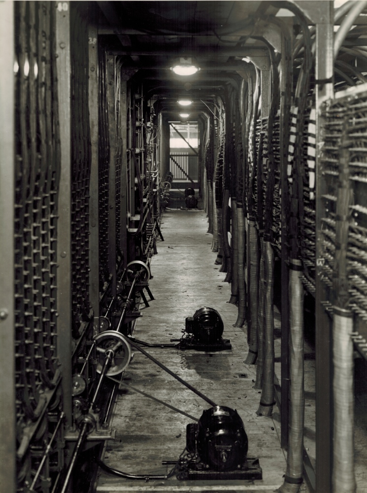
The writing on the back of this photograph reads: Drive motors on floor. "At the rear of the main switch board. Cables from Selling Booths come in behind rack on right of photo and terminate on panels on rack. From those panels leads go away to required points in V.I.R."
In Neville Mitchell's latest audio tape describing these totalizator systems, he refers to VIR cables. These are cables insulated by Vulcanised India Rubber. Perhaps the above reference to V.I.R. is that the "leads go away to the required points" with the conductors insulated by VIR (Vulcanised India Rubber).
I have seen the external cabling entering the machine room for the Julius Tote that is now on display in the Eagle Farm Racing Museum. I thought it very impressive how these big multi core cables were encapsulated in a heavy thick ductile outer material which I presumed was lead. These cables rose to the first floor from below the ground attached to the inside walls. I never had the opportunity to lift one of these however I think if this material was lead and presumably these cables were encapsulated in the same fashion in their underground runs to their destinations in other racetrack buildings, then these cables must have been very heavy and costly. I suppose lead was chosen as it is relatively inert malleable and ductile. I am sure there would have been no OH&S issues with handling these lead covered cables at the time. Today we are accustomed to running cables in plastic conduit or ducting. Multi core cables can be seen entering this space from under the floor on the right hand side of the walkway and rising up to the termination panels. This binding is different to the lead sheathed ones I have seen. This sheathing seems to have been wound around the cable bundles. As this binding does not look waterproof, I suspect these are for internal distribution within the machine room. Credence for this is provided by the comment written on the back of the photograph that states that the cables from the selling booths, which will include outside connections, are behind the racks on the right hand side of the image. It appears that what looks like arches at the top right of the image, are the lead sheathed external multi core cables rising up the wall and arching over near the ceiling and descending to the termination panels. The connections on the termination panels are soldered. The cables are all bound in looms and look quite tidy. When I worked for AWA in the early 1970s we had standard practice manuals that had a lot of information on subjects like soldering and cable loom forming. There had to be no cable seen crossed over on the outside of the loom. I saw a significant decline in this principle over the decades that followed as the cost of manpower became a major business concern.
The motors on the floor, with belts connected to pulleys on the drive shaft in the lower left of the image, provide the drive for the rotary arms of the scanners. These scanners, which are TDMs (Time Division Multiplexers) are visible at the bottom of the equipment panels, in the third image, in the White City section and there is a closer view of the scanners, in the fourth image in this section. These Time Division Multiplexers existed long before the electronics that made this concept commonplace. Click on the image to go to the Photo Gallery index.