This history of technology page contains a photograph, which is one of several belonging to the photo gallery pages which are part of several pages relating to the invention of the world's first automatic totalizator in 1913 by George Julius and Automatic Totalisators Limited, the Australian company he founded in 1917 to develop, manufacture and export these systems.
Copyright © 2015 Email - totehis@hotmail.com
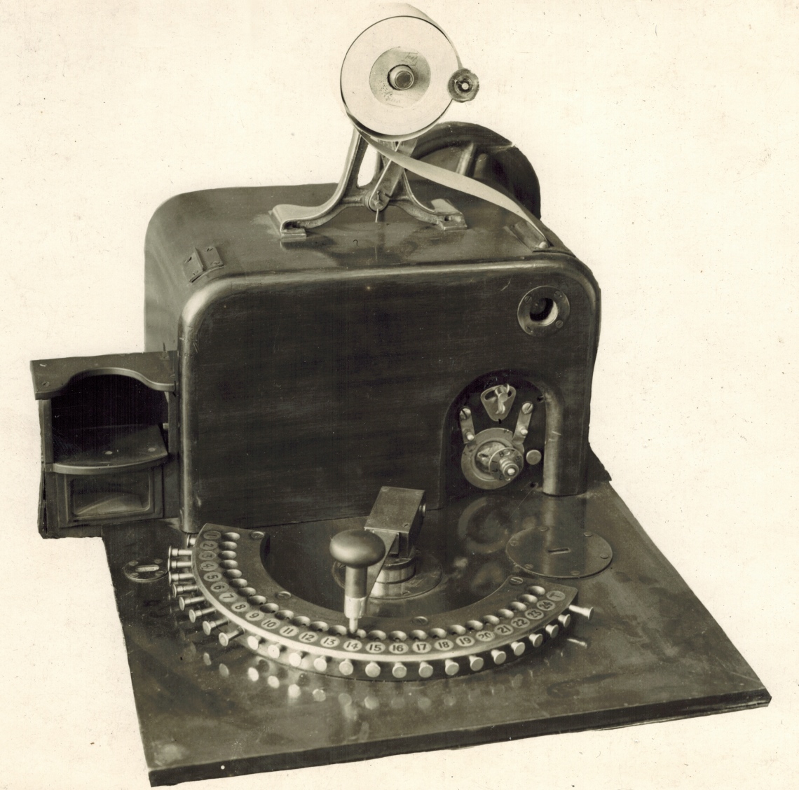
The Premier Ticket Issuer
The TIM (Ticket Issuing Machine) in this image is the same type as shown in the British Pathé website video clip, which identifies it as being in use at a Sydney racetrack in 1927. This TIM pre-dates the J prefixed numeric TIM model numbers used by Automatic Totalisators Limited and was simply called The Premier Ticket Issuer as George Julius called his totalisator system The Premier Totalisator. It is not surprising that this TIM predates the Automatic Totalisators Limited TIM numbering system as this type of TIM was used in the 1917 Randwick system, which is the same year that George Julius started the company Automatic Totalisators Limited.
It is interesting to note that the scratchings are implemented on the machine. The British Pathé website video clip prefixes the segment relating to the operation of this TIM, as it is silent, with the words Human error is eliminated - error is impossible. It is impossible to back a non runner. This is achieved by the operator entering the scratchings on the machine prior to operating. Read on after the image to see how this was achieved...
Click on the image to go back to the photo gallery
There are no photographer's markings on this print
An original copy of a historic company document titled The Premier (Julius) Automatic Totalisator, contains a low resolution picture showing a man operating a Ticket Issuing Machine (TIM) on page nine. Following is the caption beneath the image: FIG 12. Interior of ticket selling cubicle on the Randwick, N.S.W., Racecourse, showing "one-man" operation. This image and caption makes it clear that the type of ticket issuing machine shown above was used at Randwick Racecourse as the machines are the same model.
Following is an extract from this company document, which immediately follows on from the previous extract and relates to the Premier ticket issuing machines like the one in the image above. This extract is the eighth in a sequence of extracts from the company document contained in multiple Photo Gallery pages of this website. The previous extract can be read in the first page of the photo gallery in the section with the title that starts with the following words Longchamps Paris 1928 -... by selecting the thumbnail with associated text beginning with the words An image of one of the 273 J5 Ticket Issuing Machines at Longchamps. To view it, click on the image above, scroll down to the bottom of the page and select the Previous page Nav Bar option then scroll down in the Photo Gallery directory to the title just mentioned and scroll further down and select the thumbnail with the associated text just mentioned.
Ticket Values.
Each ticket issuer when installed is designed for the sale of tickets of some particular selected value, and from that issuing machine, and therefore, from that selling booth, only tickets of that value can be obtained. With the exception of the printing type on the issuer, the machines are in every other way identical one with the other, no matter what value of ticket is printed, and the Adding Machines are arranged on any predetermined scheme to permit the sale of tickets of various values. The Premier Adding Machines are now designed to issue tickets of the following relative values:--1, 2, 4, 5, 8, 10 and higher. Thus if 5/- is the unit ticket on any installation, other booths can be arranged to sell 10/-,20/-, 25/-, £2, £2/10/-, £5, £10, etc. THIS RANGE OF VALUES POSSIBLE WITH THE PREMIER EQUIPMENT IS NOT AVAILABLE ON ANY OTHER MAKE OF TOTALISATOR EQUIPMENT OTHER THAN THOSE WHICH USE PREPRINTED TICKETS, and this flexibility in ticket values has proved of great assistance in laying out totalisator equipment to meet the requirements of the betting public in the way most desired.
The next extract from The Premier (Julius) Automatic Totalisator document, which immediately follows on from the extract above, is titled Adding Machines. It is in the first page of the photo gallery in the section titled Randwick Racecourse Sydney New South Wales with thumbnail associated text beginning This image shows an ornate early large system adder. To view it, click on the image above, scroll down to the bottom of the page and select the Previous page Nav Bar option then scroll down in the Photo Gallery directory to the title just mentioned and scroll further down and select the thumbnail with the associated text just mentioned.
The type of adder used in the 1917 Randwick Julius Tote
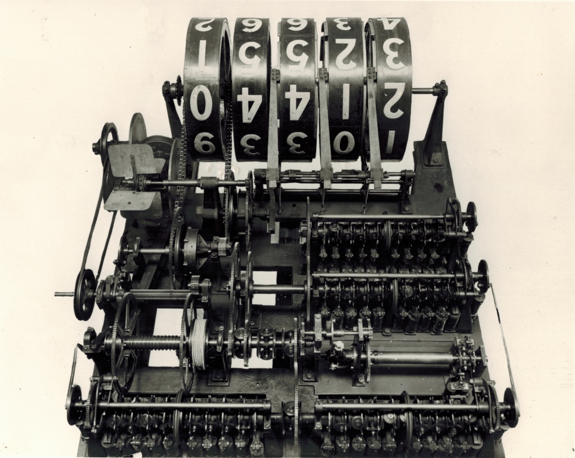
As the above extract titled Ticket Values mentions the ticket issuer and the Adding Machines or adders, I have included an extract from the company document titled Straight Betting, which makes reference to the connection of the issuing machines which are installed at the selling windows, to the adders, one of which is shown above, in the central tote processing system of that era. It reads:
Such selling windows may also be located anywhere, as required. They can be placed in the building which contains the Totalisator, or may be a mile, or ten miles away. The only limitation to the location of issuers at a distance from the Totalisator itself is the question of minimising the amount of electrical wire required. The normal voltage used in all these machines is 110 volts, direct current, and the wire used to connect the selling machines with the Totalisator is 1/18, 600 Megohm grade insulated wire.
I find the above statement very interesting. A data transmission line in 1917 claimed to operate at a distance of 10 miles or more and utilising 110 volts DC. Firstly, I don't think many technologists would have thought data transmission dates back to 1917! Secondly accepting that data was being transmitted so long ago, it is impressive that distances in excess of 10 miles over cable was possible. Finally, it is apparent there was no OH&S considerations in those days! The previous image to the one at the top of this page, in the photo gallery shows a J1 Ticket issuing machine which transmitted this information mechanically. The electronic TIMs of my era, starting with the J22, used tri-state differential lines for long distance transmission on a racecourse giving them a high common mode rejection ratio for improved noise immunity. These lines had a differential voltage of +/- 2V to +/- 3V.
The TIM shown at the top of this page, has an arc with holes on the top, graduated with runner numbers. To select a runner number the handle is moved to the desired runner number and the handle is depressed sending a locator into the associated hole in the arc and initiating a transaction cycle. Prior to operation, the operator makes sure the radial lockout buttons at the outside perimeter of the arc are pressed in for every runner that is a scratching or a runner number corresponding to a horse number in excess of the highest runner in the race. Every valid runner number should have its corresponding radial lockout button pulled out with every other lockout button pressed in. This will allow every valid runner to be selected and every invalid runner number will not allow the sell button on the handle to be depressed because of the corresponding pushed in lockout button. As can be seen from the image, runners 10 through 24 have been locked out suggesting that the highest numbered runner in the race is 9. Number one is also locked out indicating it is a scratching. T which is also enabled allows a Test Ticket to be printed if selected.
This must have been the first method of implementing scratchings. Later this was controlled in the machine room where every adder associated with a non runner would be disabled prohibiting a transaction cycle to be initiated from any TIM, on any adder associated with the non runner. In the end the scratchings were input into the system via a remote Raceday Control Console which disabled the selected adders at one centralised location rather than every operator entering the scratchings on their machine further minimising the possibility of error. There is an image of a Raceday Control Console in the first page of the photo gallery in the Harold Park section.
Prof. Bob Doran sent me a link in July 2016 to a New Zealand NGA̅ TAONGA Sound & Vision Wellington video clip of racing at Awapuni racecourse at Palmerston North in 1940 with reference number F33784. It shows the Julius Tote in operation there and the TIMs in use are the same type as the one shown at the top of this page.