This technology history page contains a photograph, which is one of several belonging to the photo gallery pages, which are part of several pages relating to the invention of the world's first automatic totalizator in 1913 and Automatic Totalisators Limited, the Australian company founded by George Julius in 1917 to develop, manufacture and export these systems.
Copyright © 1998 Email - totehis@hotmail.com
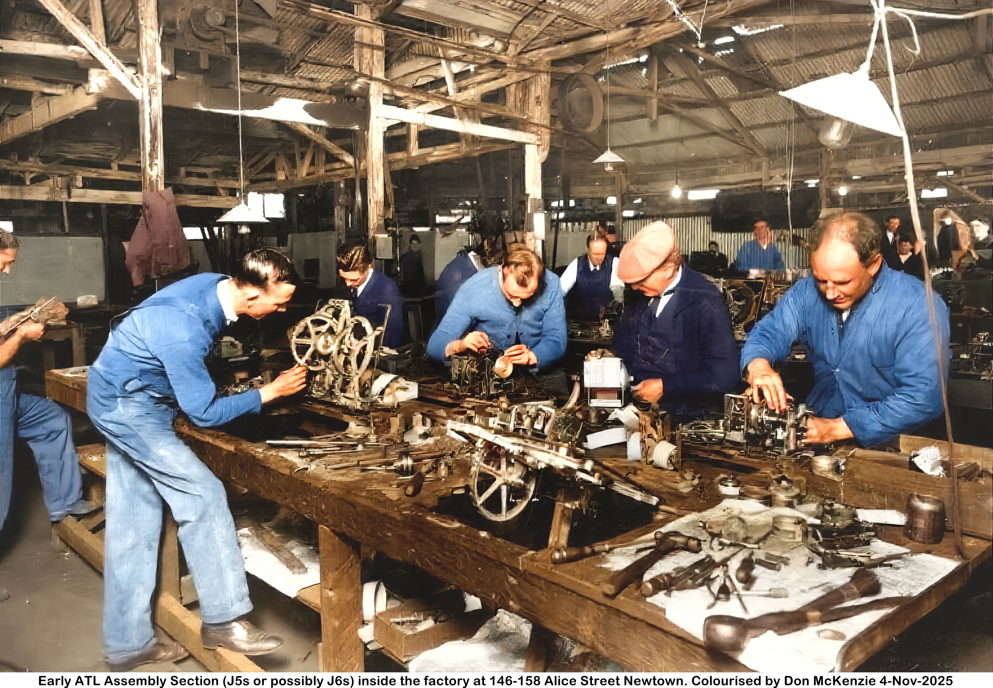
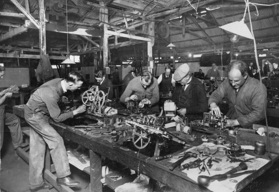
An old Automatic Totalisators Factory Assembly Section
Electromechanical Computing on an Industrial Scale
This is an early Automatic Totalisators Limited Assembly Section that is inside the Newtown factory which was located at 146-158 Alice Street Newtown. The roof is synonymous with the tin shed factory in the previous image of the Photo Gallery, which can be seen by clicking on the image below, then scrolling up and selecting the image thumbnail prior to the thumbnail for this image. It is therefore highly probable, that this photograph was taken inside the factory in the previous image.
This Ticket Issuing Machine (TIM) assembly section is manufacturing Julius Tote Ticket Issuing Machines. These TIMs are electromechanical input output devices. This shows the manufacturing of electromechanical computing terminals on an industrial scale! This is obviously long before the advent of OH&S and considerations like posture becoming important. It is interesting to note some of the timeless tools on the near workbench.
More after the image...
Click on the image to go back to the Photo Gallery
The Photographer's stamp reads: Hall & Co 44 Hunter St. Sydney
Sir George Julius made a comment in a 1932 article, which appeared in the Gippsland Times Newspaper relating to Australian workers. The content of this article is made available by the National Library of Australia on its Trove website with the following details:
1932 'HOW THE AUTOMATIC TOTALISATOR WAS INVENTED', Gippsland Times (Vic. : 1861 - 1954), 7 January, p. 3. , viewed 20 May 2016, http://nla.gov.au/nla.news-article62691937
Sir George's concluding statement in this article is: These machines have all been built in Australia in almost every detail, and are a tribute to the abilities of the Australian workman.
This comment relates to the standard of work that had been and continued to be performed in the factories of Sir George's company Automatic Totalisators Limited and is probably confirmed by observations relating to his other varied fields of endeavour. In other words, this is a compliment to Australian workmen, particularly the ones working in his factories, like the men in the above image, as well as those in the multitude of staff and factory images, in this website.
The complete transcript of the Gippsland Times article titled How the Automatic Totalisator was Invented appears on this website in the Mechanical Aids to Calculation chapter. To view this, click on the image above. Scroll to the bottom of the page and select the Go to the index menu option in the Nav Bar and select the Mechanical Aids to Calculation chapter.
I have identified the TIMs being assembled in this image as probably J5s or possibly J6s. There are some tell-tale characteristics that identify the J5 machine some of which also apply to the J6. Firstly the J5 and J6 are quite compact machines compared to some others and this is evident of the machines on this workbench.
Also, in the nearest TIM, which does not have anyone working on it, there is an arched arm near perpendicular to the flat surface of the mounting frame that is propped up at approximately 45 degrees to the bench. The top of this arm has a hole through it which is the pivot point for the print head assembly. This arm itself is pivoted at the bottom end and when the assembly process reaches a state of completeness in this area, this arm is swung down and rests on top of underlying assemblies. This brings it close to the ticket paper, which when in use will be drawn across the top of the runner number wheel, which can be clearly seen protruding from the bottom of the mounting frame into the hole in the desk.
Now looking at the TIM to the left of this one, which has the man whose legs and feet are visible working on it, we can see the underside of the machine. An arc can be seen in the top right quadrant with the convex side extending up towards the top right corner and extending somewhat into the bottom right quadrant. This is where the Horse Halo is mounted which contains a series of electrical contacts, one for each runner. On the top side of the machine the runner selector handle moves around in this arc and when the runner selector handle is in the position of a particular selected runner a wiper attached to the arc makes electrical contact which identifies the particular runner. The J5 and J6 are the only TIMs I know of where the runner selector arm sweeps around the bottom right corner of the machine. If the description of the top right quadrant seems to conflict with the runner selection handle sweeping the bottom right corner of the machine this is because the machine being described in the image is hinged up in the open position for access to the bottom side and in operation it will be closed so the top of the machine is flush with the bench surface it is installed in.
Next, moving to the opposite side of the bench, we can see the upper top left corner of the TIM, where the man working on this machine has the top of his head directly facing the camera and is third from the right hand side. His left hand is over a silver circular object. This is the main drive pulley, driven by an electric motor which is mounted on the bottom of the TIM but none of the TIMs in the picture with the bottom side visible has the drive motor installed yet. The location of the main drive pulley and the motor exactly matches the J5 and J6 machines.
Finally to the man on the far right who is looking down but closest to facing the camera. His right hand is on a drive wheel and over a tall rectangular assembly. This rectangular assembly contains the lower pivot point of the arched arm previously mentioned and sits on top of the ribbon and paper transport systems. This assembly, prominent in this perspective is characteristic of the J5.
Having identified the terminals being manufactured in this image one would think that might give some idea of the age of the photograph. As the Longchamps J5s were manufactured in Paris under supervision, with all other equipment being manufactured at the ATL Alice street factory, the TIMs in this image may be for Sydney where they were already in operation when the Longchamps project started, which opened in 1927, or possibly Singapore, installed in 1926 which also used the J5s or other sites I am not aware of that used J5s. The problem is that I do not have any documentation that indicates which years the J5s were manufactured. I know they were in Sydney when the Singapore project started so the latest possible installation for that would have been at Warwick Farm in 1925 with the previous installation in Sydney being Victoria Park in 1923. On the conservative side supposing the J5s were introduced in 1925 there were eight other installations before Longchamps. Not knowing when J5 production ceased, there were another 21 installations that were catered for by this factory before the factory moved to Chalmers street. It leaves us with a lot of supposition, however I think it would be fairly safe to say that this photograph was taken in the mid to late 1920s.
The following comment was made regarding the TIMs for the French project and probably applies to the machines being manufactured in the image above: The Ticket Issuing Machine design also was a remarkable piece of engineering and saw the introduction of a machine to sell both Win & Place tickets from the one machine. This was a big step forward and proved to be one of the main features for many years to come. The equipment for Longchamp was manufactured in the factory at Alice Street, Newtown, N.S.W. except for the Ticket Issuing Machines, which were made in Paris under supervision.
Judging by the amount of ticket paper rolls on the workbench, it looks like a lot of printing alignment and testing took place during the assembly process.
The roof in the image at the top of this page reveals a lot about the factory this photo was taken in.
Aerial View Alice Street factory post Automatic Totalisators Limited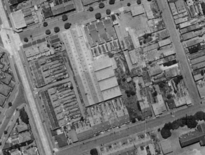
The image above titled Aerial View Alice Street factory post Automatic Totalisators Limited, was extracted from a 1949 aerial survey photograph. I received the aerial photograph image from Naomi Crago, an archivist at the City of Sydney archives when I enquired about the Newtown Project and the Alice Street factory. It is titled City of Sydney - Aerial Photographic Survey, 1949 Map 102 and is from the Historical Atlas of Sydney.
The 1949 aerial photograph was taken after Automatic Totalisators Limited had vacated this factory and moved to Chalmers street in the city. This move took place in 1933/34. How much change to the ex Automatic Totalisators Limited factory took place in the intervening years is unknown, however there is an aspect of this factory shown in the aerial image above that can be seen in the much earlier image at the top of this page.
A significant characteristic of this factory, as seen in the aerial photo from the outside, is evident in the image at the top of this page, from the inside. It can be seen in the aerial view above, that a major part of the factory consists of two very long thin neighbouring structures with A-frame roofs. It also shows what looks like from above, four parallel close together and perpendicular extensions to this major part of the factory, about half way down and on the right hand side of the long thin sections. On the top right hand side of the image at the top of this page, the distant half of an A frame section of roof is visible running near parallel to the benches. The corrugated iron can be seen running upwards and to the left of vertical. This section of roof shows the left hand side of the roof inside the right hand long thin section of the factory. In the top left corner of the image there is a section of roof where the corrugated iron can be seen rising to the right in a direction perpendicular to the first section of roof. This second section of roof is over one of the four perpendicular sections shown in the aerial view looking into the nearest of the two very long thin neighbouring structures with A-frame roofs. The bench in the foreground is well into the section of the factory that looks like the four adjacent extensions.
The second section of roof mentioned, clearly shows that this extension section of the factory has a sawtooth roof giving rise to the appearance that there are four adjacent extensions on the right hand side of the two long thin sections of the factory as seen in the aerial photograph. Above the back of the nearest man working on the TIM on the bench in the image at the top of this page, there is a pillar rising which crosses two horizontal beams in the background. The corrugated iron roof segment that is one of the teeth in the saw starts rising ramping up to the tip of one tooth. At the top left of the image at the top of the page, this corrugated iron roof ramp section disappears off the top of the photograph. At the top of and immediately to the right of the pillar to the right of the first pillar above the man working on the TIM, a very small part of the ramp section of roof can be seen disappearing behind the beginning of the next tooth ramp. The small section visible is triangular in shape. Immediately to the right of this section there is a piece of corrugated iron at right angles to the ramp. This seals the ramp section of roof from the outside at the end of the apex of the roof. Above the beam which disappears off the the top of the image at an angle of 15 degrees to the top edge of the image, between the second and third pillars to the right of the pillar above the previously mentioned man working at the bench, the corrugated iron can be seen rising to the right again. This is the beginning of the next tooth segment and the line along the top of this beam is where the top of the previous ramp drops sharply to the start of the next ramp or in other words, is the end of the last tooth and the beginning of the next. Another way of identifying this tooth joining beam is that it is located above the top side of a belt connecting an electric motor, suspended in the roof at the top of the image to the right of the pillar behind the nearest man working at the bench, to a large drive wheel on the right.
There is another image in the Alice Street group of photos in the Photo Gallery, that shows the Drum Counter Wheel displays being assembled in the neighbouring section of this factory. This Drum Counter Wheel display assembly section starts behind the three wooden pillars shown in the image at the top of this page, in the upper half and a little more than the left hand half of the image. Each beam rises behind the backs of three of the men working at the bench, the first being the man completely visible on the near side of the closest bench, the second on the far side of the same bench far left, the third to the right of the second man. On the right hand pillar of the three, there are a couple of notices or drawings attached and there is also a long black tool looking like a heavy duty pincer dangling from it. This can all be seen from this other photo from a different perspective. The woodwork support structure above these beams can be made out in both photos as well.
The first thing that I saw that planted the seed that these two photographs show parts of the factory adjacent to each other, was in the other photograph showing the Drum Counter Wheel display assembly section, where I noticed a TIM on a bench on the far right hand side of the image, which seemed to be outside of the Drum Counter Wheel display assembly section. I immediately thought this might be the TIM maintenance section shown in the image at the top of this page, that could be neighbouring the one I was looking at. I then sought further evidence that these two photographs of two different sections of the factory were adjacent to each other. I have another photo of this very TIM assembly section that is not presented on this website, as it is very similar to the one at the top of this page. The main difference is that it is from a much more elevated perspective and angled a little to the right and with no staff working at the near table. The first confirmation that these assembly sections are adjacent came from this second photograph of the TIM assembly section, when I saw some Drum Counter Wheel displays on a bench to the left of the three pillars previously mentioned and shown in the image at the top of this page.
Now with growing confidence, I sought any other evidence of the two sections being adjacent. In the photo not presented on this website, there is a good view of dark cloths that are dangled in specific areas from the corrugated iron back wall. These line up perfectly with the ones shown in the other photo which is in the Photo Gallery, of the Drum Counter Wheel display assembly section. There is one of these cloths visible in the image at the top of this page and below, the bottom right hand corner of which starts to the left of the head of the man on the right hand side of the far side of the near bench. Finally, above and to the right of that same man's head, there is a triangle shaped outline above the shiny corrugated iron section of the far wall. The apex of this triangle is formed by two planks of wood. In this far wall area, near the far right hand side of the image, there are two light sources that seem to be associated with a distant window. The lower oblong rectangle, which is the taller light source, is just below the apex of this triangle outline. This triangle is also visible in the image showing the Drum Counter Wheel display assembly section as a final confirmation that these two photographs show adjacent sections of the factory. The image showing the the Drum Counter Wheel display assembly section can be seen by clicking on the image at the top of this page, then scrolling down if necessary and selecting the image thumbnail with the associated text starting with Another image of a Workshop in the Alice Street Automatic Totalisators Limited factory .
One last trivial comment about the image at the top of this page and below. Below the knee of the man on the near side of the bench who is in full view, is a shelf. On the shelf near his knee is a paper with a strip of wood on top. On a high resolution version of this image, it looks like a newspaper page with text and faces on it. I can almost make out a sentence on it, the letters that I am sure of read ARE YOU A INKER. With some degree of uncertainty, I think it reads ARE YOU A THINKER. Unfortunately nothing else is discernible. Wouldn't a date have been wonderful!
In October 2025 Don McKenzie, a long serving Automatic Totalisators Limited engineer in Melbourne performed a colourisation of the photograph that is the topic of this page. I have left the original image above to preserve the historic essence of this website however I have included Don's marvellous image below as a stark contrast to what is possible nowadays. For me it makes the image far more lifelike: