This technology history page contains a photograph, which is one of several belonging to the photo gallery pages, which are part of several pages relating to the invention of the world's first automatic totalizator in 1913 and Automatic Totalisators Limited, the Australian company founded by George Julius in 1917, to develop manufacture and export these systems.
J22 Block Diagram Drawing No. W2809
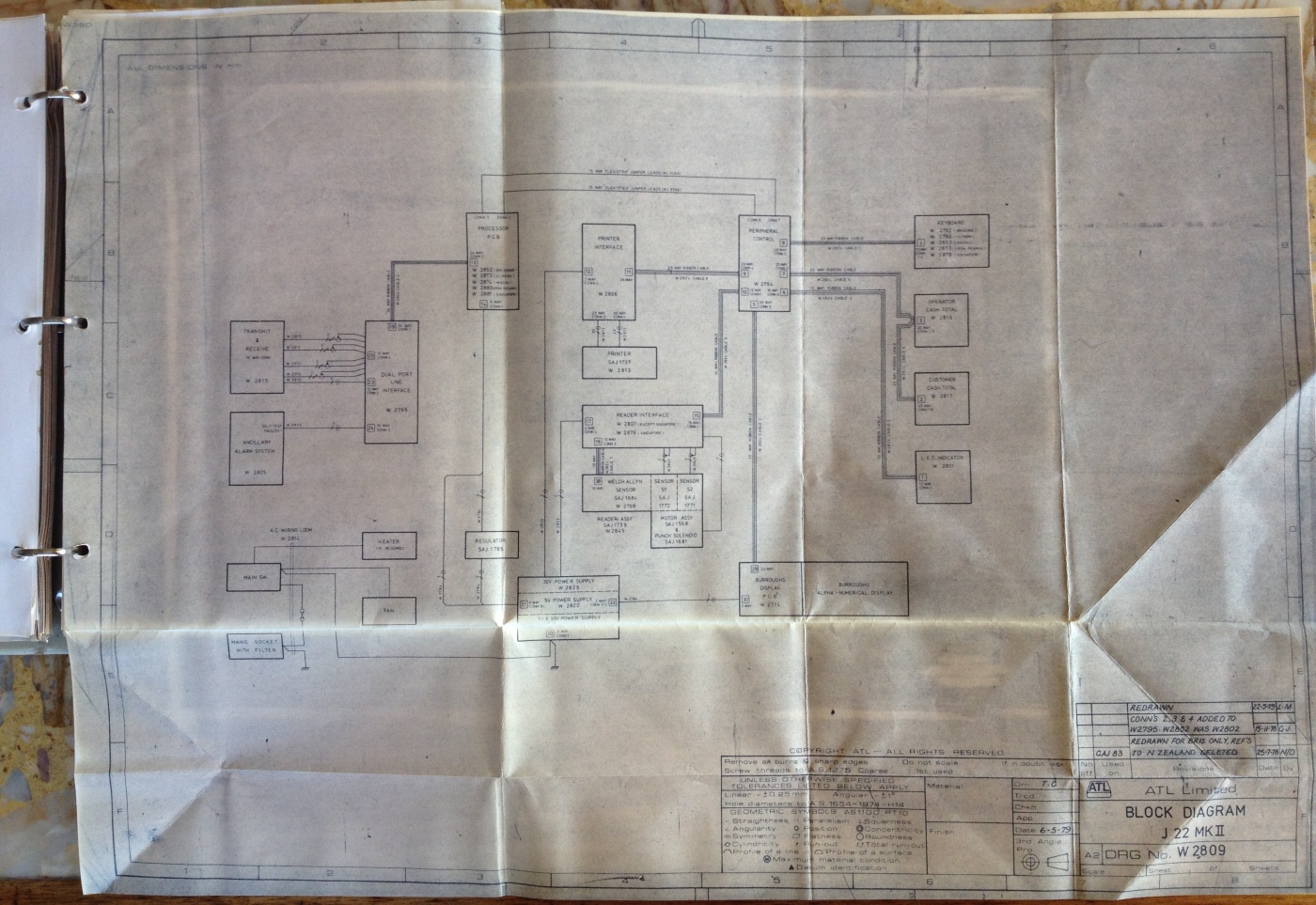
This is an image of the J22 Block Diagram extracted from the J22 Technical Manual. It shows how each of the modules in the J22 connect to each other. The block diagram is the outermost view of the machine, from an engineering viewpoint, and consequently shows the whole machine. It groups together parts of the machine that perform a particular function and places them in a box with next to no information regarding the details. As mentioned, it does indicate how the modules inside the boxes connect with each other and within each box identifies the engineering documents which provide all the detail. Usually for electronic parts of the machine the detail will be in the form of circuit diagrams and in the case of mechanical parts it will be in the form of mechanical engineering drawings containing three views if required, front elevation, end elevation and plan view. I have sacrificed the clarity of text in this diagram, with a wider view image to show how the pages unfold from the manual. The ring binder, other pages in the manual and part of the cover is visible at the top left of this image. I have deliberately not made much effort to straighten out the folds in this diagram, to demonstrate how it is folded. This manual was published during an era when manuals were in printed form and not distributed on computer media like CDs or DVDs or on the Internet as is the custom at the time of writing in 2015. I recall a period when it became popular to distribute technical information, Circuit Diagrams, Circuit Descriptions, Diagnostic Listings etcetera, on a medium called Microfiche, which greatly reduced storage space required and cut down on the use of paper. It was like photographic slides which required a specialised reader.
Click on the image to go back to the photo gallery
Photo by Brian Conlon
Following, I have provided the labels inside the blocks in the above image, to aid in reading it for those interested in the technical detail of this image. I have ordered the following list moving through the blocks in the diagram in a series of loosely formed, top to bottom columns, starting from the left hand side moving to the right. The W prefixed numbers e.g. W 2794 are drawing numbers. Every drawing has a number for indexing in the print room archives so the drawing can easily be located. Other information included in the block diagram that I have not reproduced below are details of the connectors on each module. Most of the intermodule connections are ribbon cables or other multi-conductor cables and each connector has an annotation e.g. 10 Way CONN 4 which indicates Connector 4 has 10 conductors.
The Block Diagram Text in the image
| Column 1 | Column 2 | Column 3 | Column 4 | Column 5 | Column 6 |
|---|
| | | PROCESSOR PCB
W 2852 BRISBANE
W 2873 H/PARK
W 2874 MACAU
W 2880 IPOH PENANG
W 2881 SINGAPORE
| PRINTER
INTERFACE
W 2806 | PERIPHERAL
CONTROL
W 2794 | KEYBOARD
W 2792 BRISBANE
W 2792 H/PARK
W 2853 MACAU
W 2877 IPOH PENANG
W 2878 SINGAPORE |
TRANSMIT & RECEIVE
W2815 | DUAL PORT
LINE
INTERFACE
W2795 | | PRINTER
SAJ 1737
W 2813 | | OPERATOR
CASH TOTAL
W 2819 |
ANCILLARY
ALARM SYSTEM
W2825 | | | READER
INTERFACE
W 2807-
(EXCEPT SINGAPORE)
W 2879 (SINGAPORE) | | CUSTOMER
CASH TOTAL
W 2817 |
| | | | WELCH ALLYN SENSOR
SAJ 1684
W 2769
SENSOR S1 - SAJ 1772
SENSOR S2 - SAJ 1771
READER ASSY
SAJ 1739 - W 2845
MOTOR ASSY -SAJ 1568 &
PUNCH SOLENOID
SAJ 1681 | | LED INDICATOR
W2801 |
| MAINS SW | HEATER
(IF REQUIRED) | REGULATOR | | | |
MAINS SOCKET
WITH FILTER | FAN | | 30V POWER SUPPLY
W 2825
5V POWER SUPPLY
W 2820
5V & 30V POWER SUPPLY | BURROUGHS
DISPLAY PCB
W 2714
BURROUGHS
ALPHA-NUMERIC
DISPLAY | |
Brief Description
This is an extract from the J22 Technical Manual part 1 section 3.3 page 3/2. It starts with the text Refer to Figure 1 which is a copy of the block diagram in the image above. I have added the comments in brackets to clarify the correlation with the block diagram for the not so technical readers.
The transaction details are keyed into the system by the operator using the relevant keys on the terminal keyboard. As the details are keyed in they are temporarily stored in the Processor Board (Processor PCB) and also displayed on the Burroughs display (Burroughs Alpha-Numeric Display). This enables the operator to check the keyed data and to correct any errors. When all the transaction details have been keyed in, the operator presses the TRANSMIT key (in the Keyboard). On receipt of this signal, the Processor Board converts the stored data to serial asynchronous form and feeds it via the differential mode drivers (Dual Port Line Interface and Transmit & Receive) and modem to the host processor. (We used the J22s with differential long line drivers eliminating the need for a modem).
The host processor carries out a validation check on the transaction details and, if valid, stores the details and returns data and instructions to the Processor Board. Under the control of this board, the Peripheral Control Board (Peripheral Control top of Column 5 in the above table) starts the printer motor, via the Printer Interface Board (Block titled Printer Interface). As the ticket is fed below the printer heads the transaction details are printed onto it as well as a unique ticket serial number (TSN) in alphanumeric form and also complementary bar code (A bar code is printed down both sides of the ticket, one is the one's complement of the other, providing a means of error detection on reading). Finally, a sliding, self sharpening guillotine is operated to cut the ticket to length. At the same time, the cash amount of the transaction is displayed on the Burroughs display and the Operator (Operator Cash Total block) and Customer Cash Total (Customer Cash Total block) Displays are increased (or decreased) by the same amount. If the host processor decides that the transaction details are invalid, it rejects the bet and returns a diagnostic message stating the reason for the rejection. This is displayed on the Burroughs display to enable the operator to carry out the remedial action.
Tickets that are due for a dividend are entered into the reader by the operator. The presence of the ticket is sensed and a signal is fed from the Reader Interface Board via the Peripheral Control Board to the Processor Board. Under the control of this board, the Peripheral Control Board starts the reader motor. As the ticket passes below the bar code reader, both edges of the ticket are illuminated by fibre-optic cables and phototransitors detect the presence of the upper and lower bar codes. These are amplified in the Reader Interface Board and fed via the Peripheral Control Board to the Processor Board where they are serialised and transmitted to the host processor.
The host processor confirms that the ticket is due for a dividend, against the previously stored transaction details, and returns the instructions and the amount of dividend due to the Processor Board. This board then feeds the amount of the dividend due via the Peripheral Control Board to the Burroughs display and also to the Cash Total Displays.
The LED Indicator Display provides the operator with information on the status of the terminal. Some of the information displayed is received from the Ancillary Alarm System. The Power Supply System provides the supplies for the motors, solenoids and logic within the terminal.
A brief history of the development of the J22 Ticket Issuing Machine (TIM) by Bob Plemel
Bob was a long serving engineering manager at ATL. He was an excellent mentor to me when I joined the company in 1979. His recollections of the design phase of the J22 development follows:
Development of the J22 started in about 1973. ATL realised they had to come up with a more versatile TIM that could easily be modified to print different tickets and be machine readable.
Ideas came from various sources such as:
- Dot matrix printers - Centronics, Epson, DEC LA30
- T-Scan Ltd, a Canadian company, in 1970/71 developed a mark sense terminal for the airline industry that used cards as input. It would read pencil marks on a card, print on the card, read a bar code. ATL bought some of these and named it the J20. During my break from ATL, I worked at TScan designing the circuit boards and writing DEC PDP-11 application code
- Release of Micro processors
- 1971 - Intel 4004 - 4bit CPU
- 1972 - Intel 8008 - 8 bit CPU
- 1972 - Motorola 6800 - 8 bit CPU
- The release of the M6800 was a key factor in the development of the J22. The M6800 architecture and instruction set were influenced by the then popular Digital Equipment Corporation PDP-11 mini computer. The 6800 has a 16-bit address bus that could directly access 64 KB of memory and an 8-bit bi-directional data bus. It has 72 instructions with seven addressing modes for a total of 197 opcodes. The original M6800 could have a clock frequency of up to 1 MHz. In addition to the ICs, Motorola also provided a complete assembly language development system. The customer could use the software on a remote timeshare computer or on an in-house minicomputer system
This meant we could start serious development of the J22 using PDP11's which we were already using in ATL's totalisator development, before the M6800 chips were available.
One of the most important parts of the J22 was a printer that could produce a ticket as fast and as human readable as the previous ATL "printing press" terminals - J10-11,etc. We started experimenting with a single dot matrix print head, the same as in Centronics, Epson printers.
We did not have an M6800 yet, so we used a PDP-11 with an I/O board that could control multiple input/output ports. I wished I had kept some photos of our original J22 development set-up. Try to picture a:
- PDP-11 mounted in a 6 ft rack with wide flat parallel cables running to a desk mounted wire wrapped circuit board with wires running to a "printer" . The "printer" was one 7 pin dot matrix head fixed mounted, a roll of standard colour coded J11 paper, power supply for the printer, etc
- Heath Robinson would have been proud of us
Initially we had no motor for moving the paper - tickets were printed by grabbing the end of the paper by hand and pulling it past the print head. A sensor was mounted on the paper roll to sense movement and provide interrupts back to the PDP-11
Code was written in PDP-11 assembler to sense the paper movement, then output commands to the print head to print 7 dots. This worked surprisingly well. So we mounted 3 dot matrix print heads and were then able to print 21 dots at time and soon were printing tickets that looked like tote tickets.
We did a few demos to potential customers that were in town. Once we also packed up the whole kit and sent it to Melbourne for a demo.
The feedback we got was that tickets were not that human readable as the printing font was too small compared to the older type tickets. So ATL did what they always did if they could not buy something, they would design and build a printer. Thus came the large format dot matrix printer that was eventually used in future J22s.
Next stage was to turn this "Heath Robinson" into a real product. We finally got M6800 chips so we designed circuit boards, cut code and started building a few demo terminals. As the terminals used erasable PROM for storage of the microcode, we could build demo terminals that could be used standalone to simulate actual operation by keying in bets, printing tickets and reading tickets.
The initial J22s were designed for the Royal Hong Kong Jockey Club. I remember making a trip to Hong Kong with one of the demo J22s which was demonstrated to a number of people who were impressed with the speed and versatility. They eventually bought quite a few for the new ShaTin race track.
And the rest is history.
Explanation of ATL Drawing Labelling System from Neville Mitchell
I was familiar with the ATL W Prefix drawings but was wondering about the SAJ prefixes used in the image above. I contacted Neville Mitchell who was a Draftsman with Automatic Totalisators and later was manager the Drawing office. He supplied the following information relating to the Drawing control system:
The numbering system was a George Julius dictate to JPG it was a wonderful system in its simplicity and ease of usage, I could train contract draftsmen how to use it in just an hour or so. It was so different from the dreadful AWA "Iron Duke" number method that no one understood. I will list here for you to the best of my memory all of the number categories.
| DRAWING NO. | DESCRIPTION |
|---|
| J | All single piece parts ie machined ,sheet metal, cast or plastic moulded. |
| SAJ | Sub assemblies of J parts and other part numbers. ie J22 print head, coupon reader. |
| GAJ | General assembly of all parts making a complete unit i.e. J22 terminal. |
| L | All manufactured parts for lamp panels. |
| SAL | Sub assemblies of lamp indicators. |
| GAL | General assemblies of lamp type indicators Inc. controllers. |
| Z | All single parts for Turnstiles. |
| SAZ | Sub assemblies for Turnstiles. |
| GAZ | General assemblies Turnstiles |
| CM, SACM, GACM | All computer hardware manufacture and assembly. |
| W | All general wiring diagrams related to terminals J6 through to J52. |
| WL | All general wiring diagrams related to Indicator systems. |
| WD | All general wiring diagrams related to Punch Tape Doubles. |
| WZ | All wiring diagrams & PCBs related to Turnstiles. |
| CW | All computer related PCBs assemblies and their wiring diagrams |
| | |
| | PURCHASED MATERIALS OR UNITS |
| | |
| M | All purchased items of a general nature i.e. electronic unit parts { ICs, capacitors resistors cable and wire etc.} |
| MJ | All parts directly purchased for J type terminals |
| MH | All silicon devices diodes bridge rectifiers, i.e. MH 1265 Silicon diode 1N4004 , 400 volt @ 1 amp. That's the real part number I used to know hundreds of them. |
| MZ | All directly purchased parts for turnstiles. |
| | |
| E | ATL used BPO and PMG relays made by TEI and others as well as American makes. By the late sixties they were replaced by the German mini form compact six changeover contact relays. To record a new 3000 or 600 type relay an E XXXX number was assigned. The description of the relay was recorded in a special book with a formatted page allowing for all of the build details to be correctly described. The details included the layout of the spring contact assemblies on the 1-2 right hand and the 21-22 left side of the assembled relay. Contact descriptions were >>
| M | a set of make contacts |
| B | a set of break contacts |
| C | a set of changeover contacts. |
| M/B | make before break contacts |
| HD | high current contacts. |
|
| | Magnetic coil descriptions were >>
| | Coil voltage |
| | Coil resistance |
| | Climatic requirement |
| | Dual coil detail** |
| Other details | Head end steel core slug slow make |
| | Heel end steel core slug slow release |
| **Dual Coils | The introduction of 3000 type relays into what was named "Access relay sets" spelt the end of the Julius win place totalisator Rotary Distributor and its associated "Overlap" relays. |
|
| Comments | The E part number was not a successful system as it was a tedious task to find a relay previously described so there was many duplications. Mainly the E part number was of use to the goods inwards inspection and the stores operations. Later in the assembly of the relays and for spares supply. |
| | The Mini format 6 Changeover relay was a god send in the design of relay equipment, the engineer had freedom of having six contact packs, and unused contacts were just ignored, their cost already included in each relay. These relays were always in sockets so ease of replacement, was a great step forward. |
| | All TEI stepping switches also carried an E part number, Standard production TEI switches 5 to 10 levels were carried in stores. Special modifications were usually performed by the fitters i.e. Trip current in Multi Impulse relay units. Often the wiper assemblies were modified to give a count of 100, by using two switch banks with alternate wiper 1 contacting level one 1 to 50 and wiper 2 contacting 51 to 100, in one revolution. |
| | The age of the electromagnetic relay, was a stepping stone to the now standard electronic devices and systems. All of the usual elements of modern systems were being done by relays and associated devices. Standard circuit elements i.e. OR / NOR /AND/ gates, add, subtract, timing, sequencing just to name a few. Webmaster's comment: I have added the bold emphasis to this paragraph of Neville's, as this rings an accord with me, that relay technology was a historic stepping stone. In my early years of Engineering, whilst working for Channel 10 in Sydney in the mid 1970s, I recall working on the development of a relay based automation system. From memory, it was for the Telecine machines and commercial breaks. |
| | |
| | FIXINGS |
| | All screws,nuts rivets etc. had a coded part number that was to describe each unit i.e. NT 3m hex zn: WH 3m 10 st zn: SPW 3m st zn: SC 3m 10 st ch ph zn: {no prize for working this one out!} |
| | |
| | PRINTED CIRCUIT BOARDS |
| | All PCB that is bare boards were purchase items and that carried the basic part number for each use i.e. J 1100, PCB for terminals. L lamp panels, CW 3000 for computers WZ 200 Turnstiles. |
| | |
| | DEVELOPMENT DRAWINGS |
| | There was an ad hoc system the draftsmen used for recording sketch design and draft drawings each senior designer or group had their own system. |
The J22 Processor PCB Circuit Diagram Drawing W 2852
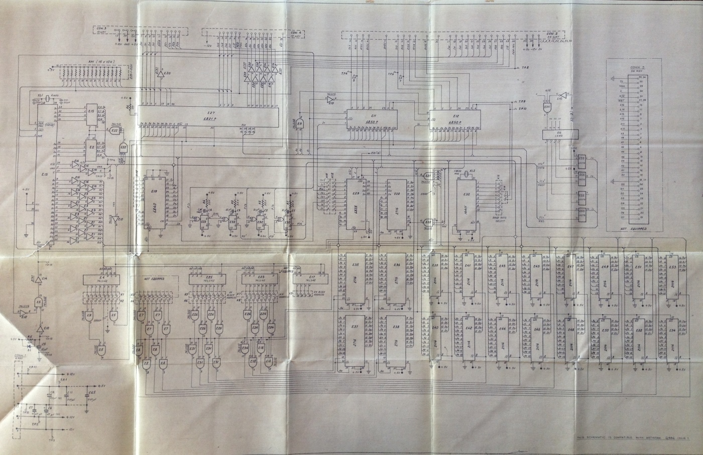
The above image is the circuit diagram, for the block in the Block Diagram at the top of this page, titled PROCESSOR PCB, visible at the top of the third column of blocks and is clearer in the text table below the image of the Block Diagram. There is a larger rendition of the Circuit Diagram in the Photo Gallery of this website. Click on the image at the top of the page to return to the Photo Gallery and select the following image.
The J22 TIM (Ticket Issuing Machine)
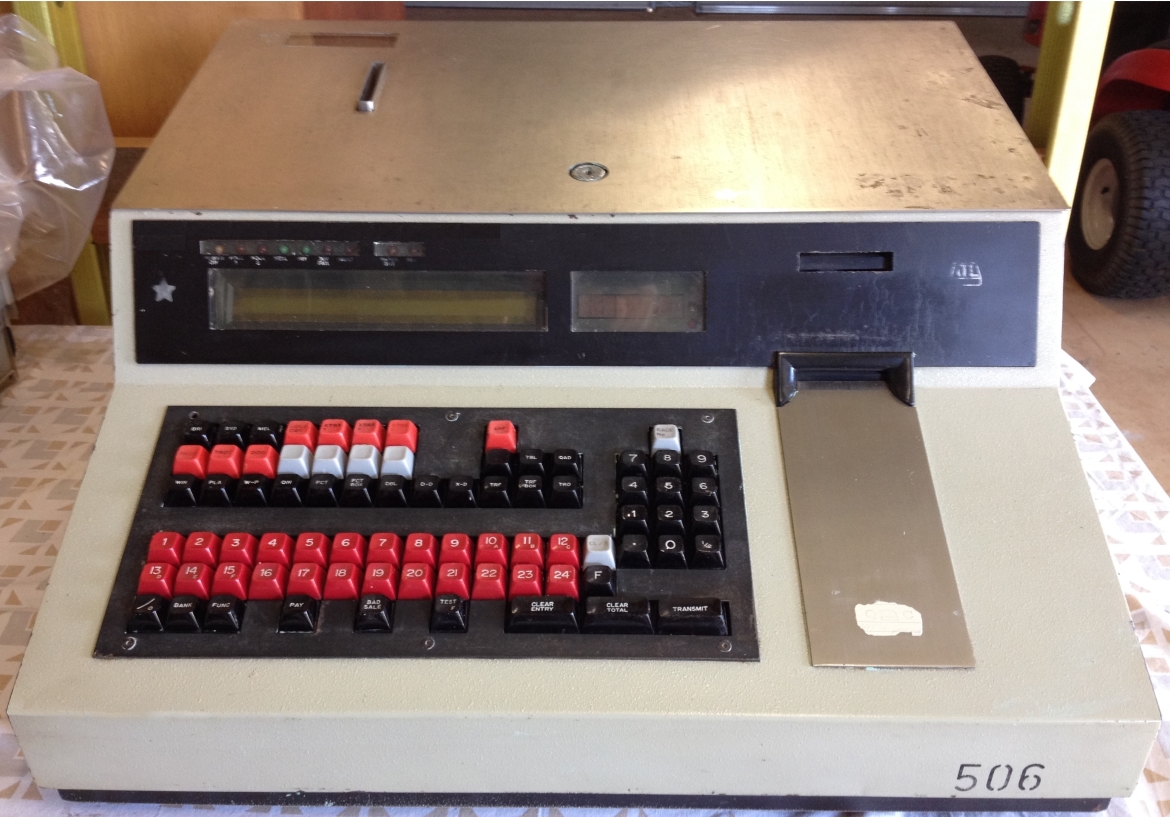
The above image shows a J22 TIM which is the subject of the above documentation. There is a larger rendition of the J22 image in the Photo Gallery pages of this website. Click on the image at the top of the page to return to the Photo Gallery and scroll up and select the thumbnail of this image immediately above.
- Thanks to Bob Plemel for his description of the Automatic Totalisators Limited J22 development process
- Thanks to Neville Mitchell for his description of the Automatic Totalisators Limited Drawing Identification System.