Click on the image to go back to the Photo Gallery
If you arrived from navigating the website, use the navigation bar at the bottom of this page.
This page contains a photograph, which is one of several belonging to the photo gallery pages, which are part of several pages relating to the invention of the world's first automatic totalizator in 1913 and Automatic Totalisators Limited, the company founded by George Julius in 1917 to develop, manufacture and export these systems.
Click on the image to go back to the Photo Gallery
If you arrived from navigating the website, use the navigation bar at the bottom of this page.
There is no photographer's stamp on this print.
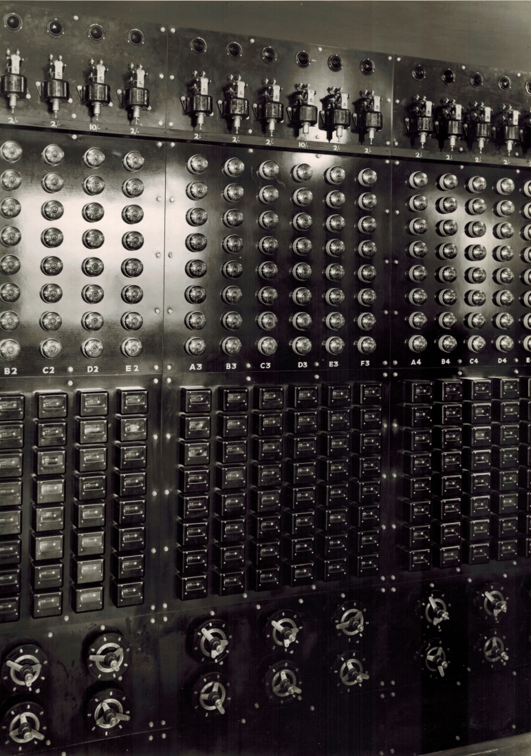
This technology history image shows a close up view of part of the Distributor and Relay Board, or what in the digital computer era would be called the front end system, of the Julius Totalizator manufactured by Totalisators Limited, the U.K. associated company of Automatic Totalisators Limited. This installation was at White City Stadium in London. This is the largest of the Julius tote installations that I am aware of supporting 320 betting terminals or TIMs (Ticket Issuing Machines).
This is a close up image of part of the Julius Tote Scanners, Relay panels and Switchboard and is part of one of the first Large Scale Real Time Multi User Systems. The writing on the back of the photo reads White City London - but typical of any tote Distributor and Relay Board in English Julius Totes.
To clarify any confusion, Scanners and Distributors are synonymous names assigned to the circular devices at the bottom of the panels in this image. My perception is that Scanner was a more modern name probably appearing with the advent of the computer era as the electronic counterpart to these electromechanical devices, were also called Scanners. Distributor was probably an older name taken from the automotive industry. Fourteen Scanners/Distributors can be seen in two rows of seven at the bottom of the image, which only shows a part of these panels. These Distributors have an inner unbroken ring and a broken concentric outer ring consisting of studs. There are three arms, seen radiating from each hub at the centre of each pair of rings, separated from each other by 120 degrees. Two of the arms are shorter than the third and they are in electrical contact with the inner continuous ring as the arm assembly rotates. The third arm is longer and it makes electrical connections with the individual studs in the broken ring as this arm passes over them. In operation the arms rotate, driven by an electric motor, and the arms electrically connect the unbroken ring to the studs in sequence. Nowadays, these devices are known as time division multiplexors yet these devices existed long before the advent of digital electronics that made time division multiplexing a common concept. These distributors create activation pulses for the Betting Circuit involving the TIMs, amongst other devices, which are attached one to each stud. If the TIM selected by the long arm passing over its stud has a transaction pending, a transaction cycle ensues recording the transaction on both the related Horse Adder as well as the Grand Total Adder and then the selected TIM prints a ticket for the customer. The unbroken ring of each distributor can be switched to a single same numbered solenoid in every adder servicing the same pool, a particular Horse Adder being selected via the the TIM's horse selector arm by an operator. The operator can also select a different pool with another complete set of adders via the Win/Place selector knob at the end of the horse selector arm. These adders are visible in the first and second photographs of the White City section of the Photo Gallery, to which this image belongs. As there are eight studs on each distributor, with a TIM attached to each one, eight TIMs are scanned by each distributor. Hence each solenoid in the adder causes the transactions from a group of eight TIMs to be recorded by the solenoid's associated escapement wheel.
To read about the adders, scroll to the bottom of this page and select the Previous page button in the navigation bar at the bottom.
Following is an extract from a company document titled Automatic Totalisators Limited Description of Electrical Circuit Diagrams. Note that this old document calls the scanners distributors and the TIMs are called Issuers:
DISTRIBUTORS:
There are a pair of Distributors for each Group of Issuers, that is for each Escapement, one for Win and one for Place. Each distributor has 8 contact studs and a common contact ring and a contact arm is continually rotated thus connecting the ring to each stud in turn. The distributors are driven at a speed of about 90 revolutions per minute by means of a motor and suitable gearing.The eight studs are connected to the 8 issuers in the group and the common ring is connected to the corresponding Grand Total Escapement, so that the distributor serves to connect the 8 issuers in the group to the one escapement magnet in turn, that is the circuit is only completed through one issuer at a time even if the whole 8 issuers have their handles depressed at the same instant. This enables one escapement to record the bets from 8 issuers.
When an issuer handle is depressed, the Betting Circuit is not completed until the Distributor Contact arm reaches the stud corresponding to that issuer. The Issuer Trip Coil plunger is arranged so that it will operate and so open the Betting Circuit again before the Distributor reaches the next Contact stud, thus enabling the escapement to make its return stroke and be ready to record the bet from the next issuer in the group if its handle has been depressed.
Above the distributors in the image are overlap relays, which hold the transaction cycle voltage from the distributor until the end of the transaction cycle after the arm has passed the stud. The relays are seen in banks above each group of distributors. Looking at the centre group of six distributors, three in the top row and three underneath, you can see a matrix of relays six across by eight down, located directly above them. Each column of eight relays provides one relay per stud on a single distributor and the six columns of relays are one for each scanner in the group of six. The six columns or relays have labels on top of each of them that read: A3 B3 C3 D3 E3 F3. The black relay covers have windows visible in their facing sides, through which the contacts of the relays can be seen.
Following is another extract from the same company document:
RELAYS ON DISTRIBUTOR BOARD:
There are a pair of relays, one for Win and one for Place for each Issuer.These relays serve to provide a definite time for the Issuer Trip Coil to function even if the Issuer Handle is depressed just as the Distributor Contact arm is leaving the Contact Stud corresponding to that Issuer.
The relay coil is connected in series with the Trip Coil and escapement magnets and so is energised when the Betting circuit is completed. The relay contacts are arranged so as to short circuit the distributor when the relay closes. Thus the Betting Circuit is maintained when the Distributor Contact arm leaves the contact stud and is only broken by the Issuer Trip Switch. The relay is very quick in operation and will close and so maintain the circuit if the Issuer Handle is depressed just as the Distributor Contact arm is leaving the contact stud.
Above the relays are isolation switches which are arranged in the same matrix as the overlap relays and share the column labels of the relays A3 B3 C3 D3 E3 and F3. These switches are used to isolate any faulty ticket issuing machines from their associated distributors. Above these six columns of switches are six labels, which identify the value the associated escapement wheel in the selected adder records, each time the corresponding solenoid in the transaction circuit the switch is in, activates it. The six labels read: 2/- 2/- 2/- 10/- 2/- 2/-, which are all shilling amounts. The top row of equipment in the image consists of the Cut-out Relays that are mentioned below. There is a close up view of one of these Cut-out Relays in the following image in the Photo Gallery index after this one. To see this, click on the image to go back to the Photo Gallery index and select the following image thumbnail. Above the cut-out relays there are what look like circular cavities in the panels, one for each column of equipment with a circular dark trim attached to the perimeter of each cavity. There are three minute bright shiny tacks or possibly rivets, I know not which, spaced around each cavity perimeter at 120 degree intervals, presumably to hold what is inside the cavities in place. A small white triangle can be seen in many of the cavities, in a high resolution version of this image and I do not know what they were used for. As these white triangles all seem to be pointing in different directions, I speculate that this may imply they were rotating when the system was in operation and the last time the system was used they all stopped in different positions. If this is the case, this motion may convey the status that ticket sales are in progress on the associated distributor. Another possibility is that these devices are alarms that identify a tripped cut-out relay, whether it be a light or a flag. Both these possibilities are in keeping with the philosophy of the escapement alarm lights above each adder in the machine room to indicate an adder that is no longer recording transactions.
There is some technical text on the back of the photograph shown in the image. I have included it here to connect with the mention of the Cut-out Relays in the last paragraph. The first sentence does not read well however I have copied it verbatim:
Cut out Relays wired in distributor common so that any excess amperage due to overlapping of bets from TIMs or faulty circuit breaker in any TIM in the group. Cut out relay is set to trip at just under 2A usually 1.85A. Thus if any TIM maintains its betting circuit unduly the plunger of cut out has time to rise and open its own circuit. If two issuers, by a wiring error, were on one TIM relay and betted simultaneously the cut out would instantly come out owing to the excessive amperage thus revealing the fault at once.From a simplistic functional rather than an implementation perspective, I see the the Scanners/Distributors and associated equipment as being in the middle of the Betting Circuit, mentioned in the Automatic Totalisators Limited Description of Electrical Circuit Diagrams document, as they constitute the front end system that interfaces the TIMs to the Adders. In this view, at the end of the betting circuit are the Adders where the transaction is recorded and the TIMs are at the start of the Betting Circuit, as nothing happens inside a Julius Tote except for the rumbling of the mainframe drive motors and scanner drive motors in the machine room, until someone buys a ticket, which is issued from a TIM. In other words, the TIM starts a transaction cycle when it is scanned.
As the distributors are an essential part of the Betting Circuit I have included another extract from the company document mentioned that gives an example of the path of the betting circuit which obviously includes the path through the distributors. Remember in this following old document extract, the TIMs are called Issuers:
To illustrate the operation of the Betting Circuit more clearly, assume that No. 22 Issuer is to Issue a 'Win' Ticket on No. 3 horse. The circuit will then be as follows-Julius Tote Control Room Switchboard
- From - pole of Main Betting Circuit Switch on Main Switchboard to common side of Starter Switches on Control Room Switchboard.
- Though No. 3 'Starter' Switch (assuming that No. 3 Horse is a Starter and the switch has been closed) to the Betting Circuit Switch on No. 3 Win Horse Unit Fuse Board.
- Through Betting Circuit Switch, Betting Circuit Fuse, Escapement Cutout Relay Contacts, No. 2 Escapement Fuse to No. 2 Escapement.
- From No. 2 Escapement to No. 3 Contact on the Win Horse Selector Segment of No. 22 Issuer.
- From this contact through Horse Selector Brush (which will be on this Contact if Handle has been depressed in No. 3 Hole in the Selector Plate and with the Handle Knob in the outer or 'Win' position) through Handle lock Switch (which will close when Handle is depressed) through Trip Coil, Trip Switch, Issuer Switch, and through Win-Place Selector Switch to 'Win' Contact (Switch will be in Win Position if selector handle is in Win Position)
- From Win Contact on Issuer through Win Pole of No.22 Issuer Common Switch on Distributor Board through coil of No. 22 Win Relay, to No. 2 Stud of No. 2 Win Distributor.
- From Common ring of No. 2 Win Distributor to No. 2 Escapement on Win Grand Total Unit through No. 2 Escapement fuse, through Escapement Cutout Relay Contacts, Betting Circuit Fuse and Betting Circuit Switch.
- From Betting Circuit Switch on Win Grand Total Unit to Contacts of Win Contactor (which will be closed if Machine is open for betting) and thence to + side of Main Betting Circuit Switch.
When the Issuer Handle is depressed therefore, the circuit is complete except through the Distributor which completes the circuit as soon as it reaches No. 2 stud. No. 22 Win Relay will then instantly close and so maintain the circuit. The bet will be registered No. 2 Escapement of the Win Grand Total Unit and No. 3 Win horse Unit and the Issuer Trip Coil will function to start the Issuer and open the Betting circuit again.
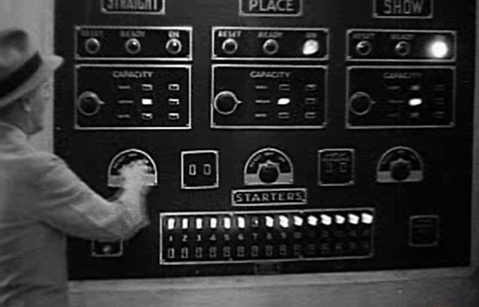
I have included the above image of the Control Room Switchboard at Hialeah in Miami as an example of the Control Room Switchboard mentioned in the first list item of the company document extract above. The starter switches mentioned in the extract can be seen at the bottom of the Control Room Switchboard below the row of illuminated lights one switch per light. Above the row of lights a sign bearing the word STARTERS can be seen. The name Starters refers to the numbers allocated to the horses that will be participating in the race. The switches are labelled 1 to 15 between the row of lights and the corresponding row of switches. This means that the highest number of runners in a race that can be catered for by this system is 15. The light corresponding to runner 7 is extinguished meaning that the corresponding switch is turned off and runner 7 is a scratching. A scratched horse is one that is no longer participating in the race.
Item seven in the list above indicates the Common Rings of the Distributors are connected to the Grand Total Units, or what were later called Grand Total Adders. This is an important part of the betting circuit, as the Grand Total Unit for a particular Pool must count all transactions for that pool, no matter which runner has been selected by the TIM, which is presently being scanned by the Distributor Arm passing over the stud the TIM is connected to. The Common Rings of the Distributors mentioned are the unbroken rings in the distributors shown at the bottom of the image at the top of this page. In an Interconnect Diagram shown in another page in this website, the following two references are made relating to the connections between the Grand Total Units and the Distributors: 8 Wires to common Rings of the 8 Win Distributors through 14 Ohm Resistors. for the Win Pool connections and 8 Wires to common Rings of the 8 Place Distributors through 14 Ohm Resistors for the Place Pool connections. The other page of this website showing the Interconnect Diagram mentioned, can be located by reading the last paragraph above the ornate wavy line below.
Following is a final extract from the company document mentioned that is extracted from a description of the Betting Circuit titled BETTING CIRCUIT./ Drawing No. 3509, which is pertinent to the distributors and confirms what was previously mentioned, that the common rings of the distributors are connected to the respective escapement magnets in the Grand Total Units. It also describes the wiring of the Issuer (old name for TIM) in the betting circuit.
From each Issuer two wires (one for Win and one for Place) are taken from the Contacts of the Win-Place Selector Switch to the Double Pole Issuer Common Switches on the bottom of the Distributor and Relay Switchboard and thence through the coils of the corresponding Relays to the Distributor Contacts. There are a pair of relays (one Win and one Place) for each Issuer and a pair of Distributors (one Win and one Place) for each Group of Issuers and each Distributor has 8 contacts corresponding to the 8 issuers in the group.The complete text from the company document titled Automatic Totalisators Limited Description of Electrical Circuit Diagrams can be read in another page in the Photo Gallery of this website. To read this click on the image at the top of this page then scroll down in the Photo Gallery index to the heading Figures from George Julius' White Paper 1920 and a Julius Tote Engineering Drawing, then select the thumbnail with the associated descriptive text starting with the sentence: This is a technical drawing showing Julius Tote interconnections.From the Common ring of each distributor, leads are taken to the corresponding escapement magnets on the two Grand Total Units.
Comments and suggestions welcome to totehis@hotmail.com 
The following page accessible via the Next page button below, contains information relating to George Julius genealogy and other latter day Tote Interest. If you arrived here from the Photo Gallery of this website and you wish to remain in the Photo Gallery, select the Top of the page button in the Nav Bar below then click on the image.
The previous page, accessible via the Previous page button below, contains extracts from the company document titled Automatic Totalisators Limited Description of Electrical Circuit Diagrams dated 15/5/1935 relating to the Julius Tote Adders, or Adding Units, as referred to in the 1935 document.
| Previous page | Go to the index | Top of the page | Next page |