This technology history page contains a photograph which is one of several belonging to the photo gallery pages which are part of several pages relating to the invention of the world's first automatic totalizator by George Julius in 1913 and Automatic Totalisators limited, the Australian company founded by George in 1917 to develop, manufacture and export these systems. George Julius was later knighted for his contribution to Australian technology.
Copyright © 1998 Email - totehis@hotmail.com
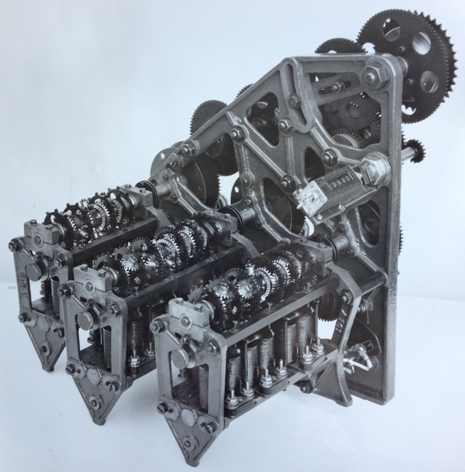
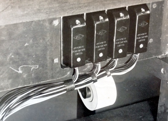
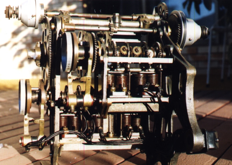
A historic 3 shaft adder used in Julius Totes
This is a three shaft adder with a capacity to support up to 240 ticket issuing machines, which is part of a much larger totalisator system. The mainframe of these systems required a large machine room to house it and contained many adders. For example, 50 in the case of a 24 runner Win Place system. That comprises 24 for each runner in the Win pool and another 24 for each runner in the Place pool and a Win pool and Place pool grand total adder. In other words, the adder shown below, totals the investment on one runner in a race.
More after the image...
Click on the image to return to the Photo Gallery
If you arrived from navigating the website, use the navigation bar at the bottom of this page.
This is an Automatic Totalisators Limited Photograph
In the image of a three shaft adder above, three adding shafts can be seen as the name implies. The three adding shaft assemblies are bolted onto the mounting plate on the right hand side of the adder and project outwards at 90° to the mounting plate, towards the bottom left corner of the image. The adding shafts sit on top of the adding shaft assemblies, with rows of solenoids beneath them. There are two coils per solenoid and each solenoid operates an escapement rocker, that allows the corresponding escapement wheel above each solenoid to advance a tooth at a time for every activation. The distance between the teeth of each escapement wheel on the adding shafts determines the value of the bet, the fewer the teeth on an escapement wheel the higher the value of the bet they register. As can be seen from the escapement wheels in this adder above, they do have some different teeth per escapement wheel ratios. Bets are recorded as angular displacement of the adding shafts and the total investment is recorded on the counter, seen attached to the right hand end of the near side of the vertical mounting plate, above and parallel to the adding shafts. The escapement wheels can clearly be seen mounted on the adding shafts above the solenoids, as they are all black. The epicyclic gears between the escapement wheels are also easy to see, as they contrast well with the black escapement wheels as they are a shiny silver like colour, which really is a shade of grey. The solenoids are activated by TIMs (Ticket Issuing Machines), that have a transaction pending as a result of the handle on their runner selection arms being pushed down. Devices called Distributors, or what later were called Scanners, triggered the pulses to the adder solenoids, from groups of TIMs attached to a particular scanner, when a selected TIM in the group, which were selected in sequence, had a transaction pending. This effectively time division multiplexed a group of TIMs onto a single solenoid. I have seen Scanners with eight or sixteen TIMs in a group. The Distributors are introduced below under the heading BETTING CIRCUIT./ Drawing No. 3509 extracts, where an example of distributors can also be seen in the image titled View of the Distributor Racks at White City London.
The specification of this adder states that it can support up to 240 TIMs. It can be seen from the right hand two adding shaft assemblies that they have six escapement wheels each and the left hand assembly has another four giving a total of sixteen escapement wheels with sixteen associated solenoids. Dividing the maximum number of TIMs supported by the number of solenoids, we get fifteen, meaning that the scanners associated with this adder had to support fifteen machines so that each group of fifteen TIMs, were multiplexed onto a single solenoid. This is an odd number of TIMs supported by the scanner, as I have only ever seen ones supporting either eight or sixteen. If a sixteen TIM scanner was used I see no reason why this adder would not support another sixteen TIMs making 256 TIMs maximum, unless there is some other reason that it is limited to 240.
The two outside escapement wheels of each adding shaft shown above are the starting points of the summation process. They are not attached to the vertical plane of rotation of an epicyclic gear but drive the near side horizontal axis bevel gear of the nearest epicyclic gear. The epicyclic gear arrangements, consist of two pairs of bevel gears which have axes at right angles to each other. The other escapement wheels on the adding shafts, have epicyclic gears associated with them and they are arranged so that the vertical axis of the epicyclic gears is attached to the escapement wheel and rotates with the escapement wheel. With the mention of vertical axis referring to epicyclic gears associated with escapement wheels, technically vertical axis should be referred to as vertical plane as the whole vertical axis rotates around the horizontal axis and continues to rotate through 360 degrees. They continue to rotate a tooth at a time as bets are registered on the horse that the particular adder is registering the bets for, until the betting is closed before the race starts. Remember, bets are recorded as angular displacement of each of the escapement wheels, which are summed by the epicyclic gears and the total is recorded on the Adder's counter. I found the adding shafts in these adders difficult to comprehend. I have only seen videos of these adders working and I lament that I never managed to find the time to see one working whilst I was working on the computer systems that eventually replaced these Julius Tote systems which were in operation in Queensland. In the videos, it is probably impossible for anyone to determine how the known function of the adders is implemented. Even slowing the action down and hand cranking the adder through different adding scenarios can be challenging to comprehend what is going on, without partially disassembling the adder, which I have never been inclined to do. I think the best way to describe these adders is to look at simplified examples, focusing on specific actions and fixing all other variables, all of which could and do occur simultaneously, when the adder is in operation.
Just as an example, consider the left hand escapement wheel of the nearest adding shaft advancing and the other escapement wheels in the adding shaft remaining at rest. First however, having mentioned rotation of escapement wheels, I will mention that starting at one end of an adding shaft and working towards the centre of the shaft the successive escapement wheels on the shaft, rotate in the opposite direction to its predecessor. At the central epicyclic gear that adds the left and right hand stubs of the adding shaft the two neighbouring escapement wheels with their associated epicyclic gears rotate in the same direction. Again these central epicyclic gears do not have an escapement wheel attached to their vertical plane axis bevel gears. Returning to the example, the rotation of that left hand escapement wheel, which has the left hand horizontal axis bevel gear of its neighbour's epicyclic gear attached to it, which also rotates and drives the vertical plane axis bevel gears in its neighbour's epicyclic gear. As this epicyclic gear has its vertical plane axis locked in place by its escapement wheel, as there are no bets being recorded on it, the vertical plane axis bevel gears rotate, driven by the left hand epicyclic bevel gear, imparting the rotation to its right hand horizontal axis bevel gear only in the opposite direction. This bevel gear is attached to the left hand bevel gear of the second epicyclic gear from the left which is attached to the third escapement wheel from the left hand side. In the same way this next epicyclic gear transfers its rotation via the vertical plane axis bevel gears, without moving its axis as it too is locked in place by its escapement wheel that has not been activated, and turns its right hand bevel gear which again is attached to the left hand bevel gear of the next epicyclic gear, which is the one in the centre of the shaft. This central epicyclic gear arrangement adds the totals of the left hand and right hand segments of the adding shaft. The rotation of its vertical plane axis gears around the horizontal axis, which is the sum of both its left hand and right hand bevel gears, is transferred via an internal shaft driving the output shaft to the right of the right hand escapement wheel. The left hand bevel gear of the central epicyclic gear arrangement on the adding shaft, rotates in the same direction to the right hand bevel gear so that the vertical plane axis bevel gears rotate in the same direction whether the left or right shafts or both are driving the epicyclic gear arrangement otherwise a subtraction takes place. As described, when the epicyclic gear has an escapement wheel associated with it, and the escapement wheel remains stationary, its associated epicyclic gear is only passing the transmission on from escapements further upstream from the central final summing epicyclic gear, the rotation being reversed as a consequence of the arrangement of the gears. Therefore, for every second escapement wheel travelling from the central final summing epicyclic gear out towards either end of the adding shaft, the rotation of the escapement wheel is reversed so that every escapement wheel rotates the final summing epicyclic gear at the centre of the shaft in the same direction. If any of the epicyclic gears in the example that were passing the rotation of upstream escapements through them, had their own escapement wheel advance at the same instant, its downstream output towards the central final summing epicyclic gear, would be the sum of the upstream rotation and the rotation of its own escapement wheel.
The summed output from each of the adding shafts in the image above, which as mentioned is represented by the rotation of the shaft to the right of the right hand escapement wheels of each adding shaft, allow large cogs on extensions from these shafts on the outside of the right hand mounting plate to advance. These are clearly seen in the image below titled Right hand view of Eagle Farm adders which shows the right hand side of an adder like the one at the top of this page. They are the two large cogwheels without any holes in them that sit above the two aluminium clutch covers below them with the clutch springs protruding from them. More on these below that image.
Now, the amazing thing about these adding shafts is that you can trip these escapement wheels singularly, or in any sequence, or in any combination or all at once and the epicyclic gears will record the correct total at their output. I was the Chief Engineer of the computer based totalisator systems utilising DEC (Digital Equipment Corporation ) minicomputers that replaced the Julius Totalisators in the Brisbane region and I inherited the technical staff who worked on them. I, along with my other computer engineering staff inducted the Julius Tote engineers and "mechanics" into the computer era. These Julius Tote experts used to delight in reminding me that these old systems could do something my computer based systems could not and that was parallel processing. My computer tote transaction processors, although they were loosely coupled multiprocessors could not perform parallel processing and consequently all transactions were processed serially, all be it so rapidly it all appeared to be happening at once. By virtue of these adding shafts in the adders of the Julius Tote, they could perform parallel processing. With the two shaft adders presented in this page for instance, which operated at Bundamba Racecourse which had the oldest shaft adders, all ten escapements could be tripped at the same instant from ten different TIMs and the adding shafts would instantaneously produce the sum of them. It reminds me of the instantaneous multipliers in digital computers as opposed to those performing shift and add algorithms. I am still impressed with this and so many other aspects of the old Julius Totes.
Note the mercury switch with part of its curved glass tube poking out at the bottom right of the adder, attached to the side plate, with two electrical connections visible. This switch was part of a security device that raised an alarm if any of the adding shafts lost drive power, meaning they no longer were recording transactions. The switch is mounted on a plate that has a pivot allowing it to rotate around a small arc. A spring on the pivot allows the plate to rotate several degrees. This plate is held in place against the tension of the spring by an arm. When the adding shaft spring unwinds it is sensed by arms on the opposite side of the three large cogs on the right hand side of the adder above and this moves the arm holding the mercury switch out of the way, allowing the spring to move the switch triggering the alarm. More on this later.
As so much has been mentioned about the escapement mechanisms, I have included the following Figure 12 and a couple of extracts from a white paper presented to the Institution of Engineers Australia on Thursday May 13th 1920 by George Alfred Julius - Member, titled Mechanical Aids to Calculation.
Figure 12 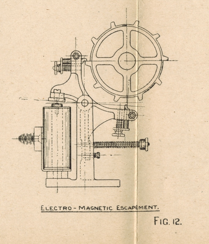
George Julius wrote, amongst other things, the following about Figure 12 above in his 1920 white paper:
Each epicyclic gear has attached to it an escapement wheel mounted concentric with it, this wheel being very similar to the ordinary escapement wheel in a clock. These escapement wheels are themselves controlled by "dead-beat" escapements which are electro-magnetically operated from the ticket-selling machines. One such group is shown in Figure 12.
When a ticket is issued, an electrical impulse is sent through from the ticket-issuing machine, which, operating the correct escapement, allows the particular escapement wheel and the epicyclic gear attached thereto to be moved forward one tooth, the driving force being the coil spring. By varying the number of teeth on the escapement wheels the amount of rotation that accompanies the issue of any particular ticket can be varied. Thus if the movement of one tooth of a " twenty-tooth " escapement wheel is arranged to record the sale of a 10s. ticket, then one tooth on a "ten-tooth" escapement wheel will accurately record the sale of a £1 ticket.
Before delving any further into these adders, I think it is important to gain some perspective as to where they fit into a Julius Tote and what the machine room equipment of a Julius Tote system looks like. I have referred to this is the past as the Julius Tote Mainframe for want of a better description. Below is an image of the Eagle Farm Julius Tote Mainframe in what used to be that system's machine room prior to it becoming part of the Eagle Farm Racing Museum.
Part of a Julius Tote Mainframe
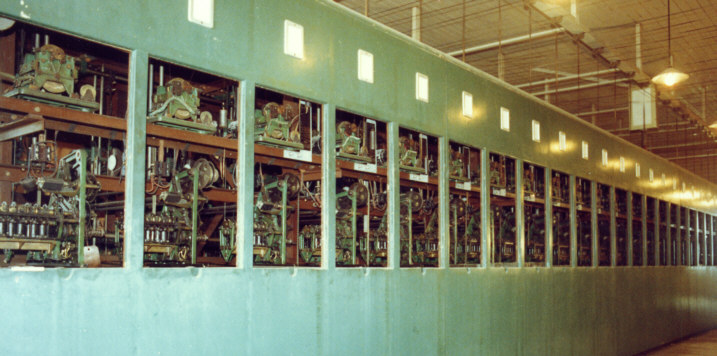
The image above is typical of the Julius Totalisators in the Brisbane region that my PDP11 Totalisator Systems replaced. They had twenty four Horse Adders plus a Grand Total Adder per pool. The image above shows part of the Place Pool processing equipment of the Julius Tote with the equipment in view repeated on the opposite side of the frame for the Win Pool. Each window in the mainframe above contains a shaft adder of the same vintage of the adder in the image at the top of this page, the only difference being that adders in the image above are Two Shaft Adders whilst the one at the top of this page are Three Shaft Adders.
The adder shown in the image at the top of this page is of the same era as the adders in the image above. The single mounting plate style of adder is recognisable and the only difference that I can determine between these two types of adders is that the ones in the mainframe shown above are two shaft adders whilst the one at the top of this page is a three shaft adder.
The white panels above each Adder window in the image above contain two information signs. When the system is turned on, the top half of these white panels show the runner number for which the adder below is recording transactions, if that adder is active in the current race. The active adders in a race are configured by the Totalisator Manager in the control room and these panels inform the engineers/mechanics in the machine room which adders are active. It also saves the machine room staff from having to count the adding windows to determine which runner an adder is associated with, as the windows do not have numbers painted on them. If the associated adder has been disabled, the runner number does not appear in this indicator. The association between any of the adders in the mainframe and the runner that it is recording bets for is fixed and the fact that the runner number is displayed only indicates that this adder is active. The bottom half of these white panels are an alarm and when they illuminate they indicate an alarm that an adding shaft spring in the adder below has completely unwound indicating that the adder is no longer recording transactions on that shaft. These pairs of indicators are described below under the heading ESCAPEMENT ALARM & STARTERS LAMPS/ CIRCUITS / Drawing NO. 3486.
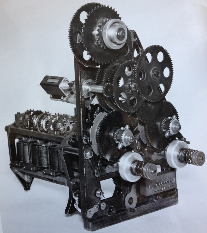
The adder shown below is exactly the same type as the ones shown in the bottom part of the windows in the mainframe image above, only seen from the right hand side. The adder below is the same vintage and design as the adder shown at the top of this page except that it only has two adding shafts while the one at the top of this page has a third adding shaft. Apart from the additional adding shaft, the image below gives a good indication of what the right hand side of the image at the top of this page looks like.
At the very top of the adder in the image below, three cogs can be seen on the same shaft. They range from largest to smallest from left to right, with the right hand one being much smaller than the other two. It can be seen that the middle and smallest cogs have a greater distance between their teeth than any of the other cogs and the valleys between the peaks are deeper and the peaks more pointed than any others. This is because these two cogs are sprockets and a chain is placed over one of these when the adder is installed in the mainframe. This chain on one of the sprockets drives the horizontal slider, which is part of the odds calculation units which exist behind the adders in the mainframe. Which sprocket is selected to drive the chain driving the horizontal slider depends on the expected turnover of the meeting. This is described in an extract from a company document below under the heading CAPACITY SIGNAL CIRCUIT./ Drawing NO. 3487. The only discrepancy between this adder and the explanation below is that this adder only supports two setting MAX and MIN whilst the description below refers to a system having three setting MAX MEAN and MIN.
Right hand view of Eagle Farm adders
The plug seen bottom right of the adder shown above, is an Automatic Totalisators Limited connector, three of which are shown in the image below titled Some Plastic Moulded ATL connectors with sockets attached to them. They are described in the paragraph below that image. Internal wires from this plug in the image above are permanently connected to the electrical parts of the adder. All the adders in the windows of the Julius Tote Mainframe shown in the image above titled Part of a Julius Tote Mainframe had these plugs attached to the adders and the sockets that connected to them had their associated wires permanently installed inside the mainframe. This made it possible to quickly replace a faulty adder during a meeting pulling the socket off it and sliding it off its mounting and pushing a replacement in place and reconnecting the socket on the plug in the replacement adder. Of course the count on the old adder would have to be recorded to add to the count of the new adder after the race had run. One of these sockets, attached to a plug can be seen end on, protruding out, bottom right in the adder image below titled Rear View of the Two Shaft Adder.
Some Plastic Moulded ATL connectors
The ATL diamond logo can be seen on each of these connectors in the image above, as well as the words Automatic on top of Totalisators on top of Limited below the diamond, on each of the connectors. Normally the plugs of this type of connector were connected to the TIMs and the Adders, and the cables emanating from the black plugs seen in the image above, probably come from TIMs. The sockets that the black plugs are plugged into, which look like they are permanently attached to a wooden cable tray, will have had cables connected to them inside the cable tray, that ran inside the cable tray to the Horse Units/Adders in the Machine Room, the subject of this page, with the scanners in the machine room providing the activation pulse for transaction cycles. Transaction cycles are performed by mechanical parts that interact with what is called the Betting Circuit as described in the company document text included below. The roll of ticket paper seen sitting on a paper dispenser in the image above, confirms that the nearest TIM is not far away, probably on top of the bench vertically above.
As mentioned the image of the adder above titled Right hand view of Eagle Farm adders gives a good indication of what the right hand side of the adder at the top of this page looks like, except the one at the top of this page has an additional adding shaft. This means that instead of two large cogwheels without any holes in them sitting above the two aluminium clutch covers below them with the clutch springs protruding from them in the right hand view of the adder image above, there will be three large cogwheels with three aluminium clutch covers and springs visible. The individual adding shaft outputs do not drive these large cogs as they do not possess the energy to do so, however these large cogs do represent the outputs of the adding shafts they are driven by. Describing the equipment in the adder image above rather than extrapolating for the three shaft adder at the top of this page, there are gears on the opposite side of the side plate of the adder that engage cogwheels on a main drive shaft when the adder above is installed in the mainframe seen above the adder image. These gears drive the input side of the clutches inside the two aluminium clutch covers seen in the adder image above. The two clutch springs protruding from the clutch covers provide adjustment for the clutch friction. There are threaded adjusting disks on the ends of the clutch spring shafts for performing friction adjustment. The output of the two clutches drive cog wheels on the clutch output shaft that engage their respective large cogwheels. This turns the cogwheels which winds a spring up in the cogwheel hub. There is an arm extending from the hub of each of the large cogwheels which are facing down to the right at about 45 degrees below horizontal. This is the fully wound position for the spring. Both arms are pushing a pawl which is best seen below the left hand arm. This pawl has engaged a ratchet wheel on the inside of the clutch cover. This stops the output shaft from the clutch rotating causing the clutch to slip as the spring is fully wound. When the adding shaft rotates due to bet traffic causing the adding shaft to draw energy from the spring the large cogwheel moves anticlockwise and the arm on the cogwheel moves away from the pawl releasing it, the clutch no longer slips winding the large cogwheel back to its fully wound position when the pawl engages the ratchet wheel again stopping the winding and slipping the clutch. If for any reason the drive to either large cogwheel via their respective clutches fails, the cogwheel will continue to rotate left as the adding shaft extracts energy from the spring. The corresponding arm continues to rotate anticlockwise, until it is in a position pointing down to the left at about 45 degrees below horizontal where it engages a lever with a pivot on the base of the adder facing up to the right, about 30 degrees to the right of vertical, with its tip close to the perimeter of the large cog. This is best seen near the left hand cogwheel. This lever activates the mercury switch previously mentioned when the extension arm of the large cogwheel contacts the lever. This raises the escapement alarm as there is insufficient energy left in the spring to energise the escapement wheels and epicyclic gears.
We have seen that the rotation of two large cogwheels without any holes represent the totals of their respective adding shafts, in the image above titled Right hand view of Eagle Farm adders. A mechanical counter can be seen attached to the left hand side of the mounting plate of the adder above the adding shaft. An extension of the counter shaft can be seen projecting out the right hand side of the mounting plate with a cog at the end of it. This engages a large cogwheel which has a ring of holes around it. A bevel gear from an epicyclic gear can be seen attached to this cogwheel. This epicyclic gear adds the two totals from the adding shafts and presents the result to the counter.
In Bob Moran's schematic below titled Bob Moran's Tote adder 10 register schematic the output of a six escapement wheel adding shaft, like the two right hand shafts in the image at the top of this page, and the one in the image above extending left from approximately mid height level of the mounting plate, can be seen at the bottom of the schematic. The six escapement wheels can be seen on the shaft with the four escapements having associated epicyclic gears labelled NOTE: These four INDEX WHEELS are attached to DIFFERENTIAL hubs, in Bob's schematic below. The central epicyclic gear can be seen and has a broken vertical line through it, which is the axis of rotation of the output of its associated two adding shaft segments. This vertical broken line joins another broken line heading right showing the drive train, which passes inside the shaft that the escapement wheels and the horizontal axis bevel gears are mounted on and driving what Bob has labelled the Graduated dial drum as indicated by the little circle on the broken line. Here the similarity between the adders shown above and Bobs schematic below digress as the latter relates to the two shaft adder below titled A Two Shaft Electro Mechanical Shaft Adder. The adders above have no Graduated dial drum. Additionally, the pawl and ratchet wheel method of slipping the clutch in the adders above is replaced by stop pegs on two slip ring disks in the adder below and the mercury switch used to trigger an escapement alarm in the adders above are replaced by slip rings and a pair of contacts on the slip ring disks in the adder shown below. Having mentioned the slip ring disks, the right hand slip ring disk, in the adder image below titled A Two Shaft Electro Mechanical Shaft Adder, which Bob calls the Graduated dial drum can clearly be seen in the bottom right quadrant.
On the left hand side of the blueprint drawing below titled Julius Poole and Gibson blueprint, a drawing of a two shaft adder can be seen which is being used as a Grand Total adder. Emeritus Professor Bob Doran from Auckland University kindly provided a copy of this drawing which he found at Riccarton Racecourse in Christchurch, after I informed him a Julius Tote still existed in one of the old tote houses on that track. It is interesting to note that the blueprint drawing below was created and drawn by A.F.J. as shown in the identification box in the bottom left corner of the drawing. A.F.J. are the initials of Awdry Julius, George Julius' son who was working for Julius Poole & Gibson, his father's engineering consulting company.
There is a box drawn on the left hand side of the left hand drawing in the Julius Poole and Gibson blueprint below, which has the following two lines written below it Grand Total Fuse Board on top of View from back of board. A group of six conductors can be seen below the right hand corner of the Grand Total Fuse Board. Near the point that these conductors descend out of the box and turn right, there is a label across them Escapement Terminals. Inside the box they attach to a representation of a connector and are labelled 3 2 1 in the top row and 6 5 4 in the bottom row. Outside the box, the conductors travel right and then rise vertically along the left hand side of a second box, which has the following two lines written below it Grand Total Unit on top of View from back. The group of six conductors rise on the left side of the Grand Total Unit or Adder, and three of the conductors peel off to the right and the other three continue up and eventually turn right. Both groups of three conductors connect to one side of a device represented by pairs of circles grouped in two rows of three. Between these two rows is the label Bottom Escapement Shaft. These devices are the pairs of electromagnets that make up the escapement solenoids. These are activated by pulses from the TIMs (Ticket Issuing Machines) which activate the escapement mechanisms which allow the escapement wheels to rotate one tooth at a time thus recording a bet for each activation. This Grand Total Unit is what is called a Two Shaft Adder. These six solenoids trip six escapements on what is called the Bottom Escapement Shaft. Another two solenoids can be seen in the drawing below, above the Bottom Escapement Shaft. These two solenoids have the label Top Escapement Shaft. These escapement shafts are mentioned throughout the 1935 Electrical Circuit Diagrams document. Like the six conductors that came from the connector titled Escapement Terminals at the bottom of the Grand Total Fuse Board for the Bottom Escapement Shaft, the two conductors for the Top Escapement Shaft come from the same connector, connections labelled 7 and 8. Each solenoid is labelled with a number and a value. The top solenoid is labelled 7 with a value of 1£ beneath and the one below is 8 with 5£ beneath. The next row of solenoids are labelled 5 1£, 3 10/- and 1 10/- and the bottom row 6 10/-, 4 10/- and 2 10/-. The escapement wheels can have different number of teeth in them, the fewer the teeth the larger the bet recorded on each activation.
The large circular device with a smaller concentric circle inside seen below these escapement shafts, within the Grand Total Unit box on the left side of the Julius Poole and Gibson blueprint below is a motor. The inner concentric circle has tangential arms on its perimeter that represent the brushes and the top brush can be seen connected to a coil like winding also inside the motor's outer circle. The two conductors attached travel down the drawing exiting the Grand Total Unit box at its bottom centre then turn left and extend to the left hand edge of the drawing where they turn upwards to the upper half left hand side of the Grand Total Fuse Board where they turn right to enter this Fuse Board where each conductor connects to a pad. Each pad is connected to the top end of a fuse. The top fuse has a - sign on the left hand side of it and the bottom fuse a + sign. The bottom end of both fuses have pads and conductors connected to both pads travel down inside the left hand side of the Grand Total Fuse Board and connect to the right hand pair of pads in a group of four pads arranged in the shape of a square with the word Motor above the word Switch sitting inside the square. I have never seen switches represented as they are in these old drawings and the following description of this switch is consistent with other switches in similar drawings of this equipment. The upper pad is the + connection and the - connection the bottom pad. The contact arms of the switch are represented by the broken horizontal lines from the right hand pair of pads to the left hand pair of pads respectively and show the contact arms in the closed position. This is a Double Pole Single Throw switch. The conductors then travel from the left hand pair of pads of the switch down the drawing and connect to the - and + pads which are the first two pads in the short row of pads at the top of the connector at the bottom of the Grand Total Fuse Board box. The motor has a label on its right hand side that reads 1/50th H.P. with the word Motor below. The motor provides energy for motivating the escapement shafts via springs and clutches for each escapement shaft. The clutches disengage when their respective springs are fully wound.
The two pairs of vertical objects drawn on the left hand side of each of the escapement shafts in the Grand Total Unit box, which look like old fashioned fountain pens with their caps on, in the Julius Poole and Gibson blueprint below, are Escapement Alarm Slip Rings labelled Escapement on top of the words Alarm Slip on top of the word Rings. These are mentioned in the ESCAPEMENT ALARM & STARTERS LAMPS/ CIRCUITS extract below. The right hand rings in each pair connect to one of two Alarm Relays shown at the bottom of the Grand Total Fuse Board seen in the image below, which are used to indicate that the associated escapement shaft spring has unwound, meaning the associated shaft has ceased recording bets. The left hand rings in each pair are connected to each other and to the Escapement Alarm Terminal in the plug labelled Escapement Terminals in the Grand Total Fuseboard rectangle, on the left hand side of the image below. These alarm relays in the Grand Total Fuse Board box below are represented by two small circular dotted lines with the words Alarm with Relay below, inside each of them. At the resolution of the image below it is difficult to recognise these words. There are two windings drawn for each Alarm Relay. The ones extending left from each dotted circle is connected to a vertical fuse on the right hand side of each dotted circle. The windings seen rising at 45 degrees to the left of the dotted circles is attached to their respective Escapement Alarm Slip Rings. Above each of the Alarm Relay dotted circles a long dotted line can be seen rising from a contact pad at about ten degrees to the left and reaches a position to the left of another contact pad. These long dotted lines represent the switch arm of the relay. When either relay is activated this arm moves left and contacts the more distant contact pad to the left of the arms. It can be seen by following the conductor that joins the two left contact pads together, that if either Alarm Relay activates, the large lamp visible near the top left corner of the image below is illuminated. This lamp has the following four line annotation Signal Lamp at above the line top of frame above the line Red Lamp above (Escapement Alarm.) These red lamps are mentioned in the Circuit Diagram document under the heading Escapement Cutout and Alarm Circuit below and relates to the Horse Units as well as the Grand Total Units. There is an image of a Horse Unit below titled A Two Shaft Electro Mechanical Shaft Adder, which later became known as a Shaft Adder, in which an escapement shaft can be seen, which later became known as an Adding Shaft and a pair of slip rings can also be seen, and are described below that image. The Escapement Alarm Signal Lamps, which are at the top of the frame as mentioned, are inside the bottom half of each of the white boxes above each adder window in the image above titled Part of a Julius Tote Mainframe.
Julius Poole and Gibson blueprint
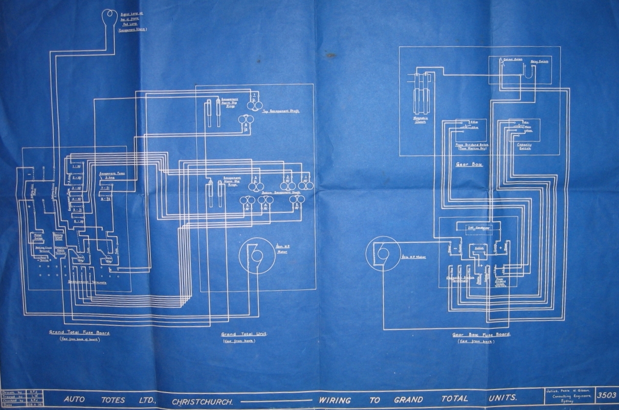
As the name Grand Total Fuse Board implies, the box bearing this label seen near the left hand edge of the blueprint drawing above, contains amongst other things, fuses. The largest group of fuses can be seen in two columns. The first column is central in the upper half of the box labelled Grand Total Fuse Board is associated with the group of six conductors entering this box horizontally, just below the top right corner of the box. As already mentioned, these six conductors are each connected to one side of their respective escapement mechanism solenoids, labelled Bottom Escapement Shaft in the blueprint drawing above, inside the box labelled Grand Total Unit, to the right of the Grand Total Fuse Board box. At the other end, inside the Grand Total Fuse Board box, these six conductors are connected to six contact pads on the left hand side of the column of six fuses. To the right of this column of contact pads there is a corresponding column of contact pads. The fuses are shown in the blueprint drawing as two dotted lines that cross each other at a very small angle, such that the one dotted line connects the top of the left hand contact pad to the bottom of the right hand contact pad and the second line connects the bottom of the left hand contact pad to the top of the right hand contact pad. This is not clear in the resolution of the blueprint image above, however the dotted nature of the lines is visible. 7 with a value of 1£ beneath and the one below is 8 with 5£ beneath. These fuses have labels beneath them starting at the top with 1 - 10/- then 2 - 10/- below then 3 - 10/- then 4 - 10/- followed with 5 - 1£ and finally 6 - 10/-. The second column of fuses to the right consisting of two fuses for the Top Escapement Shaft are labelled 7 - 1£ and 8 - 5£. It is not possible to discern this text at the resolution of the blueprint image above but it is possible to follow the layout of the drawing. The left hand column of six fuses has the following text oriented 90 degrees anticlockwise so it stands vertically on the left side, Escapement Fuse - 5 Amp. The right hand column of two fuses has the text across the top Escapement Fuses with 5 Amp below.
The gearbox shown in the drawing on the right hand side of the Julius Poole and Gibson blueprint image above is used to extract the commission from the pool grand total to arrive at the net pool total for the calculation of odds. There is a box in the lower part of the right hand drawing in the blueprint image above, which is labelled Gear Box Fuse Board with the line View from back below. Above this is another box labelled Gear Box and at the bottom of this box are two switches. The right hand switch of these two is labelled Capacity Switch, which has three settings labelled Min or Mean or Max. These settings are described in the 1935 Electrical Circuit Diagrams document below under the heading CAPACITY SIGNAL CIRCUIT./ Drawing NO. 3487. The stubby cylindrical looking object on the left hand side of the box labelled Gear Box in the top right quadrant of the blueprint image above is labelled Magnetic Clutch. It is not the same clutch as this one, however a Magnetic Clutch is mentioned in item number 8 of the first numbered list under the heading BETTING CIRCUIT./ Drawing No. 3509 extracts below, which relates to the magnetic clutches in the TIMs. Mechanical clutches in this equipment are usually used to disengage the constant motion of a motor when it is not required.
There is a motor shown in the blueprint drawing above, below and slightly to the left of this Magnetic Clutch, which has connections to the tops of two fuses located on the left and right hand sides of the Gear Box Fuse Board at mid height level. Both these fuses have the vertically oriented word Motor appropriately standing on their left hand sides, which is not legible at the resolution of the blueprint image above. From the pad at the bottom of the right hand fuse a conductor travels left and joins the right hand lower pad of another Double Pole Single Throw switch, which looks a lot like a square. From the pad at the bottom of the left hand fuse a conductor travels right and joins the bottom of another fuse and after a short descent turns right again passing underneath the body of the switch and rises to join the right hand upper pad of the switch. As previously described, this switch is also shown in the closed position by the dotted lies from the two right hand pads to the two left hand pads of the switch. The switch has the simple label inside it Switch which is the On-Switch. From the two left hand pads conductors travel down, the left conductor of the pair joining the bottom of a vertical pair of pads, which has a - sign to the right of it and the right hand conductor joins the upper of the pair of pads, which has a + sign next to it. These - and + pads belong to the connector along the base of the Gear Box Fuse Board box. There is a label to the right of the motor which reads 1/20th H.P. Motor. I have not described this motor drawing as I have already done that for the motor seen to the left of this one in the blueprint drawing above. It is interesting to note however, that this motor on the right has its coil like winding connected to both brushes, whilst the motor on the left has its connected to the top brush only.
The two shaft adder shown in the image below, is a close match to the one shown on the left hand side of the blueprint drawing above. Technically, the adder shown below is a Horse Adder, which is an adder for totalling the sales on a single runner, whilst the one in the blueprint above is a GT Adder, used for calculating the Grand Total of all Horse Adders in a particular Pool. In this version of the Julius Tote however the Horse Adder and the GT Adder were interchangeable. Another difference, is that the Adder in the blueprint has its own motor, whilst the one shown below has a drive pulley, located at the rear left corner near the top, which is not in view, which connects to a drive shaft in the mainframe that drove all the adders associated with a single pool.
In the image below, three solenoids can be seen across the bottom of the adder each containing a pair of coils. These three solenoids trip escapement mechanisms that allow escapement wheels to advance one tooth for each activation, which is the method of recording bets. Above the solenoids is a substantial horizontal rod which contributes to holding the left and right mounting plates of the adder together. To the rear and slightly above this support rod an adding shaft (or escapEment shaft as referred to in the old document extracts) can be seen with six escapement wheels mounted on it. The three solenoids mentioned trip the escapement mechanisms of three of these escapement wheels. At the same height of the three solenoids but on the other side of the adding shaft are another three solenoids which trip the other three escapement mechanisms for the remaining three escapement wheels on the adding shaft mentioned. In the Grand Total Unit, inside the tall rectangle to the left of centre in the blueprint above, at mid height level the pairs of coils in the solenoids can be seen. The three solenoids in the bottom row in the blueprint above, are the ones visible in the image below and the upper three solenoids in the blueprint are the ones mentioned on the opposite side of the adding shaft in the image below. Above the adding shaft in the image below there is another horizontal shaft with two large cog wheels on it which are inside the two mounting plates and another large cog on the right hand side of the shaft which is outside the right hand mounting plate and a smaller cog on the same shaft, outside the left hand end plate. Behind this shaft is a second adding shaft with an extra four solenoids, however although this second adding shaft is shown in the blueprint above, there are only two additional solenoids shown at the top of the Grand Total Unit rectangle in it. This second adding shaft is not visible in the image below however, the coils of the near side solenoids in the second adding shaft can be seen, above and behind the first adding shaft in the image below. This second or rear adding shaft can be seen in the image below titled Rear View of the Two Shaft Adder, above the shiny horizontal support bar that runs the width of the adding shaft with the rear solenoids visible below it. The rear row of solenoids belonging to the front adding shaft can be seen at the bottom of this rear view of the adder.
A Two Shaft Electro Mechanical Shaft Adder
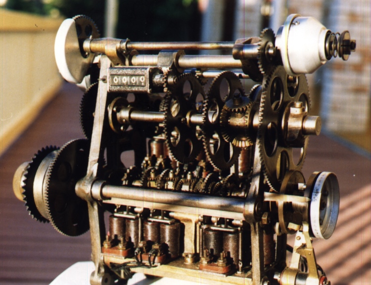
At the top right hand end of the adder shown above a shiny cone like aluminium cover can be seen. Inside the left hand end of this cone like aluminium cover, there is a mechanical clutch. This clutch prevents the constant drive from the drive shaft motor from winding the spring in the visible adding shaft, any further when it is fully wound. This is one of the clutches mentioned at the end of the second paragraph above the blueprint drawing above labelled Julius Poole and Gibson blueprint. Protruding from the right hand end of the cover a spring can be seen. This spring is the clutch spring which holds the clutch plates together and controls the friction between the plates adjustable with the nut seen on the right hand end of the shaft. The conical cover keeps dust and grime out of the clutch.
Above the substantial horizontal rod above the row of solenoids at the bottom of the adder above, the adding shaft can be seen as identified in the paragraph above the image. Adding shaft is the later name for what is called escapement shaft in the extracts from the old document titled Automatic Totalisators Limited Description of Electrical Circuit Diagrams, probably due to the fact that the shaft does not only have escapements on it but epicyclic gear trains that perform the adding function, which is the purpose of the Adder. This adding shaft extends to the right past the right hand support plate of the adder to two slip rings, which look brown in colour, and at the far right hand end a graduated aluminium drum. There is a pointer seen anchored on the outside of the right hand support plate pointing right and extending to the graduations of the aluminium disk. The slip rings and aluminium disk are located below the conical cover mentioned in the previous paragraph. Coiled on the hub between the two slip rings there is another spring. This spring energises rotation of escapement wheels and epicyclic gears on the front adding shaft of the adder, as the slip rings as mentioned are on an extension of that adding shaft. This spring is described in the second and third paragraphs below the subheading Escapement Cutout and Alarm Circuit: of the company document extract below titled ESCAPEMENT ALARM & STARTERS LAMPS/ CIRCUITS / Drawing NO. 3486. There is another group of devices, consisting of the slip rings, the spring between them and the graduated aluminium disk, which is located behind and above the one in view in the shaft adder image above, which performs the same function for the rear adding shaft, which can be seen in the image below titled Rear View of the Two Shaft Adder. In this image, the slip ring disks are on the left hand side of the adding shaft, and the aluminium cone like cover for the clutch is on the right and the main drive pulley can be seen on the left hand side of the clutch cover. The springs that energise the adding shafts can easily be seen in Bob Moran's schematic below titled Bob Moran's Tote adder 10 register schematic. At the bottom right corner the two slip rings can be seen with the spring in question between them. This is for the front adding shaft that is visible in the image above and the one for the rear adding shaft can be seen as well in Bob's schematic below, in the upper half of the page and to the left of the lower one. Bob has labelled these springs Spring Accumulator. The rear adding shaft can be seen in Bob's drawing below as well, to the left of the rear slip rings and spring.
Attached to this rear cone like cover, as clearly seen in Bob's schematic below in the top left quadrant, is the main drive pulley labelled INPUT MAIN DRIVE PULLEY, which is connected to the main drive shaft for all the adders in a single pool in the Julius Tote mainframe. Also on the shaft that the pulley is on is a cog next to the pulley, which engages with the cog wheel, seen top left in the two shaft adder shown above and top right in the image below titled Rear View of the Two Shaft Adder, which has the aluminium guard cover over the front section of it, as seen top left in the front image above. This pulley then drives the shaft seen across the top of the adder shown above and connects to the right side of the clutch inside the right hand conical cover at the top of the adder. The left hand side of the clutch drives a small cog, seen protruding out from the front of the adder on the top right hand side, in front of the shiny conical clutch cover, which then drives the large cog seen on the very right hand side of the adder on the outside of the right hand mounting plate. The bottom end of this large cog then drives a cog on a shaft in line with the front adding shaft and looking like an extension of it. This cog is out of view and has the left hand slip ring disk connected to its right hand side. It can be seen in the image above that the top of the left hand slip ring disk overlaps the bottom end of the large cog where it engages this out of view cog. This gear train just followed winds the adding shaft spring up, that exists between the two slip ring disks. This spring provides the energy for rotating the escapement wheels and epicyclic gears on the adding shaft. With no betting activity the right hand slip ring, that is connected to the adding shaft mentioned, will not rotate as none of the escapement mechanisms are being activated. This left hand slip ring rotates, driven by the gear train we have followed, until a stop peg on the left hand slip ring, which overlaps the right hand slip ring stop peg, engages this second stop peg which is mounted at the same radius, allowing the left hand slip ring to travel no further, which causes the clutch in the drive train to break friction and slip. The stop pegs are mentioned in the second paragraph below the subheading Escapement Cutout and Alarm Circuit of the company document extract below titled ESCAPEMENT ALARM & STARTERS LAMPS/ CIRCUITS / Drawing NO. 3486. They can also be seen in Bob's schematic below titled Bob Moran's Tote adder 10 register schematic, between the two pairs of slip rings, shown engaged with each other which is their normal resting position, labelled Driving Studs shown rotated 90°. With betting activity the escapement wheels rotate, with the epicyclic gears summing the rotations towards the centre of the adding shaft, where the left and right shaft segment totals are summed by another epicyclic gear and passed through the shaft to the right hand slip ring disk, where its rotation corresponds to the sum total of the rotation of each individual escapement wheel. As its associated stop peg has advanced, the stopped peg of the stop peg pair on the left hand slip ring disk is now free to allow the left hand slip ring disk to rotate again and the clutch no longer slips and the left hand slip ring disk follows the right hand slip ring disk. This means the whole gear train is moving again, now recording bets. The large cog wheel on the right hand side of the adder in the image above, which connects the left hand slip ring cog to the cog that is driven by the clutch, is mounted on a shaft, that looks like the same shaft that the other two large cog wheels are attached to, on the inside of the right hand mounting plate. We now come to an excellent example of the epicyclic gears that exist in the adding shaft as this large right hand cog wheel on the outside of the right hand mounting plate is connected to the right hand bevel gear of a large epicyclic gear arrangement on the inside of this mounting plate, clearly visible in the image above.
The large epicyclic gear arrangement, consists of two pairs of bevel gears which have axes at right angles to each other as seen in the Adder image above. The function of this epicyclic gear arrangement is to add the rotation of the large cog on its right hand side to the rotation of the not quite so large cog on its left hand side and impart that summed rotation to the second large cog on its left hand side, which drives the small cog on the total counter of the adder, which is above and to the left of the left hand large cog. As a direct consequence of this last sentence, an essential property of the adding shafts can be seen and that is, there is an internal shaft segment which transfers the output rotation of a single epicyclic gear or an epicyclic gear at the centre of an adding shaft to the next stage of the gear train, in this case a single epicyclic gear passing the output past the large cog on its left to the second large cog on the left. This can clearly be seen in Bob Moran's schematic below titled Bob Moran's Tote adder 10 register schematic. To the right of the centre of that schematic the four bevel gears of the large epicyclic gear arrangement can be seen looking like a tall oblong thick lined rectangle with chamfered corners with the label Differential "A" on the right hand side of it. There is a broken vertical line joining the upper and lower bevel gears, which is the axis of rotation for those bevel gears. This vertical axis is not fixed to the horizontal axis that the other two horizontal axis bevel gears are mounted on and is free to rotate in a vertical plane around the horizontal axis, always in the same direction. In other words, the escapement wheels to the left and right of the epicyclic gear rotate in the same direction. It is the rotation of the vertical axle around the horizontal axle of this epicyclic gear arrangement that is the sum of the rotation of the large cog on the right of the epicyclic gear with that of the rotation of the left hand large cog. It does not matter if the left hand large cog, which is connected to the left hand bevel gear of the epicyclic gear, causes the vertical axle to rotate around the horizontal axis, or if the right hand cog connected to the right hand bevel gear causes the rotation and if both are rotating, the vertical axle just rotates further.
Much of what follows has already been described with respect to the adding shaft in the image at the top of this page, however this rendition of an example refers to Figure 9 below. The adding shaft in Figure 9 is exactly the same adding shaft arrangement as that of the adding shafts in the adder in the image at the top of this page, as well as that shown in the adder in the image above titled Right hand view of Eagle Farm adders, as well as that shown on the left hand side of the image above titled Julius Poole and Gibson blueprint as well as the one in the adder in the image above titled A Two Shaft Electro Mechanical Shaft Adder and finally the one seen at the bottom of the schematic shown below titled Bob Moran's Tote adder 10 register schematic. As previously mentioned at the centre of the adding shaft shown below, which is the same arrangement as the one described in the fourth paragraph below the image at the top of this page, there is an epicyclic gear that sums the rotation of the right and left stubs of the adding shaft and is labelled T. Further let's take the situation where the escapement wheels, associated with epicyclic gears marked B and A in the image below, to the left and the right of this central final summing epicyclic gear, have the same number of teeth on them. The escapement wheels in FIG.9 below are the six tall slender wheels perpendicular to the horizontal shaft. When only one escapement wheel rotates a single tooth, say the left hand one, this rotation is imparted from the escapement wheel associated with the epicyclic gear marked B in FIG.9 below via the shaft segment marked Q to the left hand bevel gear of the epicyclic gear marked T and hence to the upper and lower bevel gears of T that rotate around the vertical axle, driven by the teeth on their left hand side. This rotation then causes the vertical axle of T to rotate around the horizontal axis propelled by the teeth on the right hand side of the upper and lower bevel gears, engaging the teeth of the stationary right hand bevel gear, which is held in place by shaft segment P, and rolling along the arc of the teeth on the right hand bevel gear. Segments Q and P rotate in the same direction, which is clockwise when viewed from the left hand end. In the case of a mini shaft adder that I have, which is one from a Mini Julius Tote System I kept from being discarded, the output of the adding shaft is via a cog attached to this centre shaft final summing epicyclic gear at T, rather than via a shaft as in the case of Figure 9 below. Let's assume for the time being there is such a cog that rotates with this final summing epicyclic gear in Figure 9. As this output cog in my mini shaft adder has a different number of teeth on it to the escapement wheels, the rotation of the escapement wheel in the example moves the output cog five teeth. The shaft in Figure 9 below, that performs the function of transmitting the output instead of this cog, is driven by the rotation of T around the horizontal axis, with T's connection to this shaft being identified by the circle at the centre of T, can be seen horizontally passing through the centre of epicyclic gears to the right marked A and C and extending out of the adding shaft to the right. In the adder in the image above titled A Two Shaft Electro Mechanical Shaft Adder, the output shaft of the front adder that is in view, drives the graduated aluminium drum wheel and its associated right hand slip ring disk seen at the bottom right of the adder. This immediately shows the latest output of this front adding shaft and moves the position of the stop peg with it. When the drive from the clutch winds the spring up again, by rotating the left hand slip ring disk, the spring having provided the energy associated with the adding shaft drive train rotation as described in the second last paragraph above, also advances the counter seen on the front of the adder above and the attached stopped peg of the stop peg pair catches up with the stop peg on the right hand slip ring disk where it is stopped and rotation ends. With the stop pegs engaged again the counter on the adder displays the current total of both adding shafts in the adder unit, provided the rear adding shaft is also at rest. The process off rotating the centre final summing epicyclic gear in Figure 9 below from the left hand escapement wheel, is exactly the same if the right hand escapement wheel had originated the motion, except it would be the right hand bevel gear of T in motion driven by the escapement wheel at A through shaft segment P, with the upper and lower cogs of the central epicyclic gear rolling across the stationary teeth on the left hand cog producing the same five tooth movement of the output cog. If both the left and right escapement wheels advance a tooth at the same instant, there is no comparative motion between the left and right large cogs so the upper and lower bevel gears of the epicyclic gear arrangement do not rotate around their own vertical axis at all and instead, the vertical axle rotates twice the distance around the horizontal axis than for the example individual escapement wheel motions and the output cog moves ten teeth, which is equal to the sum of the two single escapement wheel movements.
Figure 9 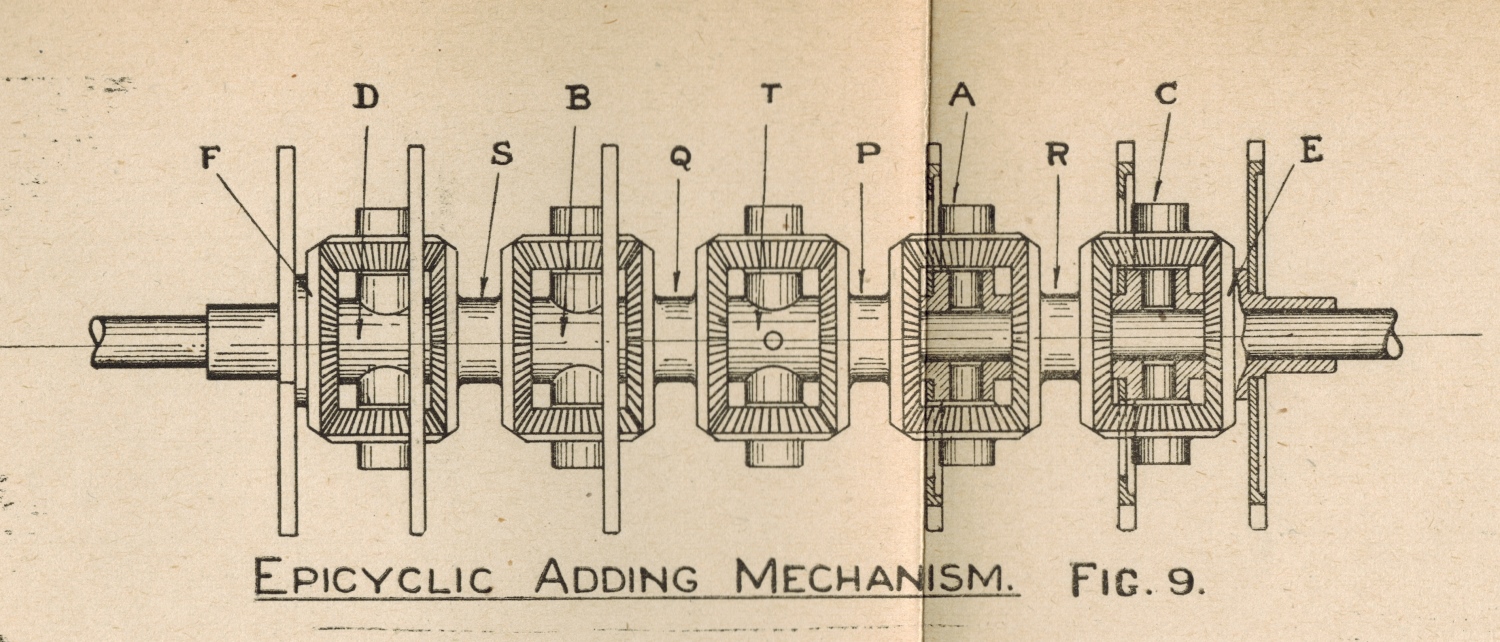
Figure 9 above is extracted from a white paper presented to the Institution of Engineers Australia on Thursday May 13th 1920 by George Alfred Julius - Member, titled Mechanical Aids to Calculation. I have included it here, as it is from a historic 1920 document from George Julius and it completely matches the front adding shaft of the two shaft adder shown in the image above. Additionally it completely matches the adding shaft seen at the bottom of the 21st Century schematic from Bob Moran below titled Bob Moran's Tote adder 10 register schematic. There is a date 05-03-2013 on Bob's Schematic bottom left, indicating that Bob created the schematic below, at most seven years shy of a century after George Julius' drawing. The fact that Bob created the drawing in 2013 is probably due to the fact that it was the centenary of the first Julius Tote commencing operation at Ellerslie in New Zealand in 1913.
In Bob Moran's schematic below titled Bob Moran's Tote adder 10 register schematic the output of a six escapement wheel adding shaft, like the two right hand shafts in the image at the top of this page, and the one in the image above titled Right hand view of Eagle Farm adders extending left from mid height of the mounting plate, can be seen at the bottom of Bob's schematic below. This is also the same adding shaft as can be seen in the image above titled A Two Shaft Electro Mechanical Shaft Adder, as well as George Julius' Figure 9 above. Furthermore, Bob Moran's schematic was created by studying the same type of adder as the one above titled A Two Shaft Electro Mechanical Shaft Adder, which is also shown from the rear in the image below titled Rear View of the Two Shaft Adder. On the subject of sameness, the adder shown in the image above titled A Two Shaft Electro Mechanical Shaft Adder and the rear view of the same adder below, is the same type as the Grand Total adder shown on the left hand side of the blueprint drawing above titled Julius Poole and Gibson blueprint. The six escapement wheels can be seen in Bob Moran's Schematic below, on the shaft with the four escapements having associated epicyclic gears labelled NOTE: These four INDEX WHEELS are attached to DIFFERENTIAL hubs. The central epicyclic gear can be seen and has a broken vertical line through it, which is the axis of rotation of the output of its associated two adding shaft segments. This vertical broken line joins another broken line heading right showing the drive train, which passes inside the shaft that the escapement wheels and the horizontal axis bevel gears are mounted on and driving what Bob has labelled the Graduated dial drum as indicated by the little circle on the broken line. The broken line then rises travels left across what Bob has labelled the Driving studs shown rotated 90° then descending to make a right hand U turn and rising to drive the right hand bevel gear of a large epicyclic gear. This large epicyclic gear can easily be seen in the image above titled A Two Shaft Electro Mechanical Shaft Adder. There are three large cogwheels mounted on a horizontal shaft, two inside the adder and the third mounted on the outside of the right hand mounting plate of the adder. The large epicyclic gear is in between the centre large cogwheel and the left hand side of the right hand mounting plate of the adder. There will be two such epicyclic gears that will sum the rotations of each of the three adding shafts of the adder at the top of this page as already described, which will be used to drive the counter in that adder. As Bob's drawing relates to the two shaft adder, there is only one of these epicyclic gears before the counter in Bob's schematic below. The vertical broken line through the centre of this large bevel gear in Bob's schematic below, then joins a broken horizontal line leading left. The small dot on the join between these two lines indicates connection which means the vertical shaft drives the horizontal shaft segment to the left but not the right. The bevel gears at opposite ends of the vertical plane axle rotate in opposite directions to each other, so one of these bevel gears has to be free wheeling. The horizontal dotted line can be seen travelling left from the little circle specifying a drive train connection, passing the left hand large cog wheel and connecting to the two cog wheels further left where the little circles on the dotted line specify connections to those cogs.
The image below shows the back of the adder shown in the image above titled A Two Shaft Electro Mechanical Shaft Adder.
Rear View of the Two Shaft Adder
In this paragraph, I will refer to the image above titled A Two Shaft Electro Mechanical Shaft Adder as the front view image and the image above titled Rear View of the Two Shaft Adder as the rear view image. The left hand large cog in the group of three large cogs, seen in the front view image, is the rear adding shaft counterpart to the large cog on the right, which is for the front adding shaft, so far as rewinding the adding shaft springs is concerned. So far as transferring the output of the respective adding shafts to the large epicyclic gear is concerned, the middle large cogwheel in the front view image, is the rear adding shaft counterpart of the right hand large cogwheel for the front adding shaft. Both the left hand large cogwheel and the right hand large cogwheel are downstream of their respective clutches, which wind up their respective adding shaft springs through their inner slip ring disks until they catch up with the outer slip ring disks that represent the instantaneous betting totals for their respective adding shafts. This representation is the total angular displacement of the adding shafts since betting commenced. As the adding shaft outputs rotate, their rotation is recorded on the counter in monetary investment units. The graduated aluminium drums at the left hand end of each adding shaft in the rear view image above, shows the remaining part of the total. The two rear adding shaft slip ring disks, which are brown in colour, can be seen in the rear view image to the right of the large cog attached to the outside of the left hand mounting plate. The left hand slip ring disk of this pair has the graduated aluminium drum on its left hand side. The front adding shaft slip ring disks are also visible in this rear view image below and to the left of the first pair. The two rear shaft slip ring disks are attached to the output shaft of the rear adding shaft that can be seen to the right of the right hand slip ring disk. Both pairs of slip ring brushes can clearly be seen with the tips of their arms in contact with their respective slip rings on the perimeter of their slip ring disks. Both slip ring brushes for each slip ring pair is mounted on the same pivot below their respective slip ring pair. The left hand large cog of three in the front view image, which is downstream of its clutch as mentioned, can be seen in the rear view image. The rear adding shaft clutch conical like aluminium cover can be seen top right of the adder in the rear view image. Immediately to the left of the clutch is the main drive pulley, which provides the input to the rear clutch on the right, and immediately on the left and attached to the pulley is a cog which provides the drive for the front adding shaft clutch via the cog in front and slightly above. This front cog drives the very top shaft in the adder running from the far right to the far left of the adder where it drives the clutch seen at the top left of the rear view image as previously discussed in the front view description. As the front view description uses the front view image, the cog that drives the large cog seen in the rear view image on the left hand side, cannot be seen in the front view image so I will point it out here. Near the top left corner of the rear view image, just to the right of the aluminium conical like front clutch cover there is a small cog on the long horizontal shaft across the top of the adder. This cog is not driven by the horizontal shaft but the output of the clutch on the left. This cog looks as if it drives the large cogwheel below it, however it really drives a cog hidden in the rear view image, which can be seen top right projecting out of the front of the adder, immediately to the left of the aluminium clutch cover. It is this cog that drives the large cogwheel on the left hand side of the adder in the rear view image. In the front view image, at the top right section of the left large cog there is a small cog on the shaft behind it, which drives the large cog. In the rear view image of the adder, the output from the top right clutch for the rear shaft, is connected to the shaft extending left from the centre of the clutch pulley and cog assembly, without any driving connection to the pulley and cog, extending to the left hand side of the adder. The small cog mentioned in the front view image, can be seen approximately in the middle of this shaft mentioned extending across the adder in the back view image. The large cogwheel seen engaged with this small cog, in the rear view image, and forward of the small cog is the leftmost cog of the three large cogs seen in the front view image. This is the means of winding up the rear adding shaft spring.
 Go back to the index
Go to the bottom of the page
Go back to the index
Go to the bottom of the page
Finally, on the subject of the adder in the image above titled A Two Shaft Electro Mechanical Shaft Adder, back to the left and right slip rings seen low down at the far right hand side of that adder. These slip rings are two metallic circular strips mounted on the perimeter of two insulating disks, which are mounted in the proximity of each other on a shaft. Apart from the two stop pegs mounted on the inside surface of both disks mentioned previously, there are a pair of electrical contacts, one on each disk surface at the same radius, projecting out from each slip ring disk towards the other's slip ring disk. They are so arranged that when there is no betting activity they are close to each other back to back but not in contact with each other and are kept from getting any closer together by the stop pegs stopping slip ring disk rotation in the closing direction. When betting activity takes place, the right hand slip ring disk advances, driven by the adding shaft which increases the distance between these electrical contacts. Under normal operation, the left hand slip ring then advances, driven by the clutch as it is no longer being forced to slip by the stop pegs, and the contacts return to their back to back but separated position when the stop pegs again stop rotation. If for any reason the drive train through the clutch fails, then the left hand slip ring disk will not rotate to chase the right hand slip ring disk and the contacts between the slip ring disks will continue to separate until they are 180 degrees apart from each other and then start to close with each other again, this time face to face. In this relative movement between the left and right slip ring disks the stop pegs do not engage again, but the two contacts between them eventually meet, which represents the closing of a switch. At this point the associated adding shaft spring has insufficient energy left to operate the adding shaft and this switching action raises an alarm. The rest of this switch circuit involves the conductive slip rings as previously identified. In the image above titled Rear View of the Two Shaft Adder, to the right of the large cogwheel on the left hand side of the adder, the left hand graduated aluminium drum wheel seen with the two brown slip ring disks on the right hand side, are for the rear adding shaft. The same assembly for the front adding shaft can also be seen below and to the left. A fulcrum can be seen with two arms projecting upwards which are conductive. Below each of these assemblies is a shaft with a pair of long contact arms rising upwards with their conductive tips in contact with the conductors of their respective slip rings which run around the perimeter of the slip ring disks. The left hand contact arm of each pair contacts the rear of the left hand slip ring and the right hand contact arm of each pair contacts the near side of the right hand slip ring. The tips of these long arms are what are called, brushes that bear on the slip rings, in the old company Description of Electrical Circuit Diagrams document. The contact arms between the slip ring disks already described, that made contact representing the closing of a switch, are each electrically connected to their respective slip rings, so that once the contacts meet as a result of a drive failure, the left slip ring arm is connected to the right hand slip ring arm as the rims of the slip ring disks are conductive. The left and right hand long arms have electrical wires attached to them, down below the fulcrums as seen in the image above, that connect them to the Alarm Relays for the Escapement Alarm as described in the paragraph above the blueprint drawing above titled Julius Poole and Gibson blueprint. The electrical contacts previously mentioned between the slip ring disks, can be seen in Bob Moran's schematic below. Looking at the pair of slip rings bottom right labelled Slip ring contacts, referring to the conductive perimeters of the slip ring disks, these contacts which close the switch are shown in their normal back to back position in Bob's schematic at the bottom end of each slip ring pair. There is a pointer pointing to the right hand contact with the following text 37 Index to activate alarm 3.5 units counter Normally open electric contacts shown rotated 90° Contacts make at 355° ACW rotation signalling a drive fault.
Following is a diagram of the adder shown in the two images above titled A Two Shaft Electro Mechanical Shaft Adder and Rear View of the Two Shaft Adder . It looks like a diagram produced by a company documenting its engineering products, however it was produced by Bob Moran who is an engineer who had his own engineering company Precision Dynamics, and has a passion for history. Bob studied the Julius Totes and the type of adder above and created the drawing below, almost half a century after this machinery became redundant. When I start to think I am obsessional about this history, works like the drawing below remind me that I am just a beginner.
Bob Moran's Tote adder 10 register schematic
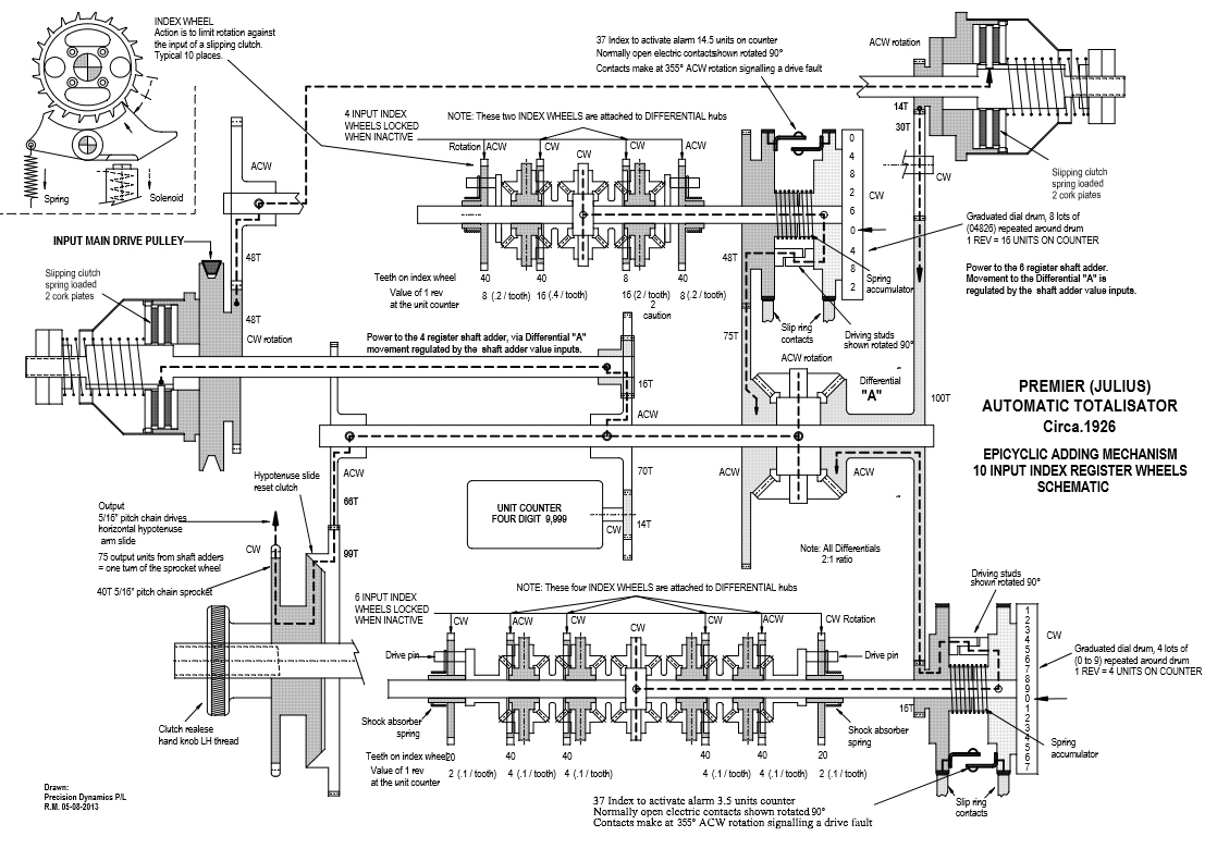
The drive train I have described as seen in the image above titled A Two Shaft Electro Mechanical Shaft Adder can be seen in Bob Moran's schematic above. I started describing the drive train of the Adder shown in the mentioned image above, in the third paragraph below the image titled A Two Shaft Electro Mechanical Shaft Adder starting with the drive pulley. This drive pulley can be seen in Bob's drawing above, near the left hand side above mid height level, labelled INPUT MAIN DRIVE PULLEY. To the right of the top of the pulley, is a dotted line identifying the drive train mentioned. The drive goes through the cog, which is the one at the top left of the adder in the image above, with the guard cover over the front part of it. The dotted line then rises again, although this is just for the sake of the schematic as the left hand stub of the shaft shown in the schematic, actually joins the right hand stub, shown higher up and at the right hand side of the schematic, which represents the horizontal shaft seen at the very top of the adder in the image above titled A Two Shaft Electro Mechanical Shaft Adder. The dotted line in the schematic above then enters the clutch assembly, with its unmistakable cone cover seen in the image above of the two shaft adder, top right. The drive then passes through the clutch and down through the large cog wheel on the far right hand side of the adder to drive the left hand slip ring disk, which is part of the assembly shown at the bottom right hand corner of the adder in Bob's schematic, with the graduated aluminium drum on the right hand end of it. Most of this can also be seen in the image above titled A Two Shaft Electro Mechanical Shaft Adder. In Bob's schematic above, the rim of these slip ring disks have a label below them that reads Slip ring contacts, as the rims are conductive and the old Automatic Totalisators Limited Description of Electrical Circuit Diagrams document refers to these rims as Slip Rings. The brown looking Slip Ring Disks, around which the slip rings are mounted, and the graduated aluminium drum, are also clearly visible in the image of a two shaft adder above. To the right of the left hand slip ring disk in Bob's schematic above, is the right hand slip ring disk, with the graduated aluminium drum attached to its right hand side. The drive train dotted line, is seen travelling left into the adding shaft from the small connection circle on the right hand slip ring disk. The spring between the two slip ring disks can be seen in Bob's diagram, which energises the adding shaft, which in turn moves the graduated drum and its adjacent slip ring disk. This is the front adding shaft, visible in the two shaft adder above titled A Two Shaft Electro Mechanical Shaft Adder, as previously described. It can also be seen from Bob's diagram above, that the output of this adding shaft is from the centre epicyclic gear, with the rotation of the escapement gears at either side being summed from the outside to the middle, where the middle epicyclic gear has no associated escapement wheel, however it sums the inputs of the right hand gears with that of the left hand gears. Bob's schematic shows the output from this middle epicyclic gear is transmitted from the little circular connection indicator at its centre to the right hand slip ring disk via the broken horizontal line.
As the right hand slip ring disk rotates as a result of bet traffic causing adding shaft movement, the Stop Pegs mentioned in the Automatic Totalisators Limited Description of Electrical Circuit Diagrams, or what Bob has labelled Driving Studs, which are seen engaged with each other between the left and right slip ring disks in his schematic above, separate. The left hand slip ring disk no longer being held by the stop pegs, starts to chase the right hand slip ring disk, as it is now driven by the clutch as it is no longer being caused to slip by the stop peg in the right hand slip ring disk. The large cog is now in motion again until it catches with the adding shaft and the stop pegs stops it again. This action is seen in Bob's diagram by the broken line rising from the centre of the adding shaft parallel and close to the left hand side of the graduated drum, progressing up and then left through the stop pegs then down, performing a right hand U turn, then up past the bottom half of the large cog, on the right hand side of the adder when viewed from the front. It rises to the hub of the large cog wheel where it turns left and is connected to the right hand bevel gear of the large epicyclic gear arrangement, which I have described in the fourth paragraph below the two shaft adder image above titled A Two Shaft Electro Mechanical Shaft Adder. We have just followed one input to this large epicyclic gear, which represents the total transactions recorded by the front adding shaft presented as rotational displacement. Immediately above this large epicyclic gear, which is shaped like a tall rectangle in Bob's schematic above at mid height level to the right of centre, are the slip ring disks and graduated drum of the rear adding shaft. In a similar fashion to the path from the front adding shaft the broken line can be seen emanating from the centre of the rear adding shaft seen central in the top half of Bob's schematic above, travelling right to the centre of the right hand slip ring disk for the rear shaft, and then down passing parallel to and to the left of the associated graduated drum. It then turns left through the rear adding shaft stop pegs and the left hand slip ring disk onto a cog attached to its left hand side, down through that cog which drives another sizeable cog, which is attached to the left hand bevel gear of the large epicyclic gear arrangement, the movement of which represents the sum total of the rear adding shaft. The sizeable cog mentioned, can be seen in the image above titled A Two Shaft Electro Mechanical Shaft Adder, in the middle of the three largest cogs in the adder. The cog that drives this middle cog can be seen in the rear view image of the adder above titled Rear View of the Two Shaft Adder, attached to the right hand side of the rear adding shaft slip ring disk pair. The large epicyclic gear now sums these two totals, as indicated by the vertical broken line joining the top and bottom bevel gears in the large epicyclic gear in Bob's schematic above, the rotation of which around the horizontal broken line output shaft, represents the grand total and the dotted line runs left showing the drive train of this output shaft. The broken line passes through another connection identifying small circle, which is attached to a cog that drives the cog attached to the counter display, shown Bob's schematic above as a rounded corner fat rectangle with the words UNIT COUNTER above FOUR DIGIT 9,999 shown inside. This cog that drives the counter cog, is the left hand large cogwheel of the three largest cogwheels in the image above titled A Two Shaft Electro Mechanical Shaft Adder and as previously described, this cog is also the means of winding up the rear shaft adder spring. The other cogs further left of the counter driving cogs in Bob's schematic above are associated with the odds display system.
At the bottom of Bob Moran's Tote adder schematic above, he has made a comment that appears at the far left and is repeated on the far right escapement wheels, that are at the ends of the six escapement wheel adding shaft. There are arrows from each comment to their respective ends of the adding shaft that reads Shock absorber spring. These are best seen on the left hand ends of the two adding shafts in the image above titled Rear View of the Two Shaft Adder. On the left hand side of the left hand escapement wheel, which is one of four on the rear adding shaft, there is something that looks like a notch on the shaft that the escapement wheels are mounted on. Inside the notch there is what appears like a substantial gauge wire wrapped around. This in fact is not a single piece of wire but four or five strands of the spring Bob is referring to. The same thing can be seen on the front adding shaft in the same image above. Extending the left hand edge of the near graduated aluminium drum, which is to the left of the notch mentioned, vertically downwards between the left hand slip ring disk arm and the left hand mounting plate, you come to a similar notch on the left hand side of the left hand escapement wheel, with the spring wire visible inside it. I suspect the reason for these springs is that the end escapement wheels of the adding shafts do not have an epicyclic gear arrangement directly attached to them, so they are capable of accelerating faster than the inner escapement wheels that are limited by the inertia of the epicyclic gears. The springs allow these escapements to advance faster than the rest of the adding shaft gear train and the springs probably assist the rest of the adding shaft to catch up. As can be seen in Bob's schematic, the adding shaft segments end in what Bob has termed the Drive pin. The two drive pins, one at each end poke through an arc in their respective escapement wheels, so that the escapement wheel can advance as the drive pin lags behind in the arc. The springs provide tension which returns the drive pin to its original position up against the end of the arc which is closest to the direction of rotation.
The following image shows the adders seen in the adder windows in the mainframe shown in the image above titled Part of a Julius Tote Mainframe being assembled in the Meadowbank Factory. As previously stated these adders are like the one shown at the top of the page, only instead of being a three shaft adder these are two shaft adders being assembled.
Adder Assembly in the Meadowbank Factory
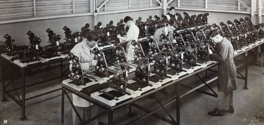
These adders demonstrate that mechanical computing existed on an industrial scale as these systems required significant production numbers of adders and TIMs as well as other ancillary equipment long before the advent of the digital computers that replaced them. These adders are an essential component of these early on-line real-time multi-user totalizator systems.
I have included extracts from a company document titled Automatic Totalisators Limited Description of Electrical Circuit Diagrams below, that relate to the adders.
The second paragraph below the next heading mentions the Control Room Switchboard. There is an image of such a switch board below titled Julius Tote Control Room Switchboard. This switchboard was located at Hialeah racecourse, which is in Miami in the United States.
From a simplistic functional perspective, as opposed to an implementation perspective, I see the end of the BETTING CIRCUIT to be the Adders where the transaction is recorded and the TIMs, I see as the start of the BETTING CIRCUIT, as nothing happens on a Julius Tote, except for the rumbling of the mainframe drive motors and scanner drive motors in the machine room, until someone buys a ticket, which is issued from the TIM. In this view the bit in between the TIMs and the Adders is the front end system, consisting of the Scanners/Distributors and associated equipment.
Following are the extracts from the 1935 company document titled Automatic Totalisators Limited Description of Electrical Circuit Diagrams mentioned:
BETTING CIRCUIT./ Drawing No. 3509 extracts.
The diagram my be extended to cover any number of horse units each of which may have any number of escapements and escapement shafts, the principle being identical in all cases.
On the Main Switchboard there is a Main Betting Circuit switch and fuses. From the - side of this switch a common feed is taken to the common side of a bank of 'Starters' switches on the Control Room Switchboard in the Manager's Office, there being one switch for each horse unit.
From the other side of each of these switches a lead is taken to the "Betting Circuit" switch on the corresponding Win and Place Horse Unit Fuse Boards.
The circuit through each horse unit is then as follows -. Through the Betting Circuit Switch and Fuse and through the normally closed contacts of the Escapement Cutout Relays (the operation and purpose of these relays is described elsewhere) to the common side of the escapement fuses, there being one fuse for each escapement and thence to the escapements.
From the escapements the circuit now proceeds to the corresponding contacts on the Horse Selector Segments of the corresponding issuers, that is the wire from No. 1 escapement on No. 1 Win Horse Unit is looped into the No. 1 Contact on the Win Horse Selector Segments of all issuers in No. 1 Group and so on.
From the Common ring of each distributor, leads are taken to the corresponding escapement magnets on the two Grand Total Units.
The circuit through the Grand Total Units is as follows. Through Escapement magnet and corresponding escapement fuse, through contacts of Escapement Cutout Relay and through Betting Circuit Fuse and Switch.
From the Betting Circuit Switch of each Grand Total Fuse Board a lead is taken to the contacts of the Win and Place Contactors on the Main Switchboard and thence through those contacts to the + side of the Main Betting Circuit Switch and Fuse.
Webmaster's notes:
The Grand Total Fuse Board mentioned in the paragraph above can be seen in the blueprint drawing above titled Julius Poole and Gibson blueprint inside the box labelled Grand Total Fuse Board, next to the left hand side of the blueprint. Additionally, the Betting Circuit Switch mentioned in the fourth paragraph below the title above, can be seen in the Grand Total Fuse Board, can be seen in the blueprint drawing above. In the third column of contacts, in the connector shown at the bottom of the Grand Total Fuse Board box in the blueprint drawing above, connected to the top contact of three, a conductor can be seen drawn rising vertically upwards with another line rising at 45 degrees to the left of the first. This line at 45 degrees, is a bent arrow pointing to the contact mentioned, with the text Betting Circuit Terminal written above the horizontal part of the arrow. The vertically rising line meets a contact pad from which a horizontal dotted line extends to the right. This horizontal dotted line has the label Betting Circuit Switch below it. Additionally the horse unit referred to in that fourth paragraph below the title above, can be considered the same as the Grand Total Unit in the tall rectangle to the left of centre in the blueprint drawing above.
Item 3 in the list below, is the BETTING CIRCUIT SWITCH ON HORSE UNIT FUSE BOARDS. The Horse Units are almost the same as the Grand Total Units, and the Betting Circuit Switch mentioned in the previous paragraph relating to the Grand Total Fuse Board is the same as the one in the Horse Unit Fuse Boards mentioned below.
I have cut out items in the list below that have nothing directly to do with the adders. All references in the list below, to escapement magnets, horse units, adding unit, adding escapements, grand total escapement magnets, grand total unit, escapement or units are referring to the Adders like the ones in this page.
The function and operation of the various switches, relays etc. in the circuit are as follows.
- MAIN BETTING CIRCUIT SWITCH AND FUSES ON MAIN SWITCHBOARD.
This switch controls the whole of the betting circuits on both poles. This switch is closed at the beginning of the day and is kept closed during the whole of the day.
- STARTERS SWITCHES ON CONTROL ROOM SWITCHBOARD.
These switches control the negative supply to each horse unit and enable the Manager to cutout all units except those for the actual 'Starters' in the Race. This prevents tickets being sold on Scratched horses. These switches are operated by the Manager before each race.
- BETTING CIRCUIT SWITCH ON HORSE UNIT FUSE BOARDS.
This switch controls the negative supply to the corresponding horse unit and enables the Mechanic to cutout a Horse Unit if any trouble occurs and so prevent further betting on that Horse until the trouble has been fixed. These switches are left closed for the whole of the day.
- ESCAPEMENT CUTOUT RELAYS ON ADDING UNIT FUSE BOARDS.
These relays automatically trip and interrupt the Betting Circuit if the driving gear to the adding unit fails. The operation of these Relays is described elsewhere.
- ESCAPEMENT MAGNETS ON HORSE UNITS.
These magnets operate the adding escapements which record each bet on the appropriate horse and Grand Total Unit.
- HORSE SELECTOR SEGMENT ON ISSUER.
These selector segments operate with a moving contact arm which is controlled by the Selector Handle of the Issuer and so connect the Issuer to the Horse Unit corresponding to the Horse for which the Ticket is to be issued.
- ISSUER TRIP COIL AND TRIP SWITCH.
This Trip Coil is in series with the escapement magnets. When the Betting Circuit is completed the appropriate Horse and Grand Total Escapement Magnets and the Issuer Trip Coil are all energised at the one time. The Trip Coil operates a solenoid plunger which at the end of its stroke, opens the Issuer Trip Switch and so interrupts the Betting Circuit and at the same time the plunger releases a mechanical latch on the Issuer and closes the circuit for the magnetic clutch and the Issuer then prints and issues the ticket.
The trip coil plunger is arranged so that it is slower in operation than the escapement magnets so as to ensure that the trip switch is not opened before the escapement magnets have operated.
- WIN-PLACE SELECTOR SWITCH ON ISSUER.
This switch is operated by the Issuer Selector Handle and serves to connect the Issuer to either the Win or Place Adding units as required.
- DISTRIBUTORS.
There are a pair of Distributors for each Group of Issuers, that is for each Escapement, one for Win and one for Place. Each distributor has 8 contact studs and a common contact ring and a contact arm is continually rotated thus connecting the ring to each stud in turn. The distributors are driven at a speed of about 90 revolutions per minute by means of a motor and suitable gearing.
The eight studs are connected to the 8 issuers in the group and the common ring is connected to the corresponding Grand Total Escapement, so that the distributor serves to connect the 8 issuers in the group to the one escapement magnet in turn, that is the circuit is only completed through one issuer at a time even if the whole 8 issuers have their handles depressed at the same instant. This enables one escapement to record the bets from 8 issuers.
When an issuer handle is depressed, the Betting Circuit is not completed until the Distributor Contact arm reaches the stud corresponding to that issuer. The Issuer Trip Coil plunger is arranged so that it will operate and so open the Betting Circuit again before the Distributor reaches the next Contact stud, thus enabling the escapement to make its return stroke and be ready to record the bet from the next issuer in the group if its handle has been depressed.
- RELAYS ON DISTRIBUTOR BOARD.
There are a pair of relays, one for Win and one for Place for each Issuer.
These relays serve to provide a definite time for the Issuer Trip Coil to function even if the Issuer Handle is depressed just as the Distributor Contact arm is leaving the Contact Stud corresponding to that Issuer.
The relay coil is connected in series with the Trip Coil and escapement magnets and so is energised when the Betting circuit is completed. The relay contacts are arranged so as to short circuit the distributor when the relay closes. Thus the Betting Circuit is maintained when the Distributor Contact arm leaves the contact stud and is only broken by the Issuer Trip Switch. The relay is very quick in operation and will close and so maintain the circuit if the Issuer Handle is depressed just as the Distributor Contact arm is leaving the contact stud.
- WIN AND PLACE CONTACTORS ON MAIN SWITCHBOARD.
These Contactors control the positive supply to the two Grand Total units and thus no betting can occur when they are open.
They are magnetically operated and only close when the Managers and Mechanics Control Switches are closed. They are also automatically opened by the operation of the Stewards switch. The circuit controlling these Contactors is described elsewhere.
Webmaster's notes:
The Starters Switches mentioned in item 2 in the list above can be seen at the bottom of the image below titled Julius Tote Control Room Switchboard below the word STARTERS with the row of lights indicating which runners are active in the current race.
Item 4 in the list above is titled ESCAPEMENT CUTOUT RELAYS ON ADDING UNIT FUSE BOARDS. As these boards are almost identical to the Grand Total Fuse Board the Escapement Cutout Relay mentioned can be seen in the blueprint drawing above titled Julius Poole and Gibson blueprint, only it is labelled Alarm Relay as described in the paragraph above the blueprint drawing above.
Item 5 in the list above is titled ESCAPEMENT MAGNETS ON HORSE UNITS. These Escapement Magnets mentioned, which are electromagnets, are part of what today is called a solenoid. the escapement trip mechanisms are activated by solenoids as a result of pulses from the TIMs. These Escapement Magnets/solenoids, are described in the third paragraph above the image above titled Julius Poole and Gibson blueprint.
Item 12 in the list above is titled DISTRIBUTORS. I have included the image below that shows these distributors, which were Time Division Multiplexers that existed long before the digital electronics that made this concept commonplace. These distributors made it possible for each solenoid in the shaft adders to support up to 16 TIMs:
View of the Distributor Racks at White City London
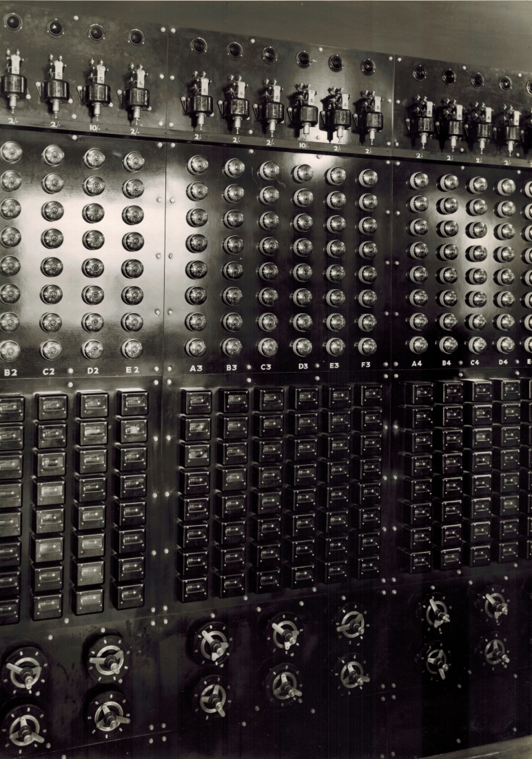
In item 12 in the list above the first sentence reads: There are a pair of Distributors for each Group of Issuers, that is for each Escapement, one for Win and one for Place. These Distributors are the circular devices at the bottom of the Distributor Racks at White City London in the image above, one row for the Win Pool and the other row for the Place Pool. Item 12 also states Each distributor has 8 contact studs and a common contact ring and a contact arm. The common contact ring is the continuous ring around the centre of the scanner and the 8 contact studs can be seen arranged in a circle around the continuous ring. The contact arms shown in the image above are a little different to the simpler straight ones. In many installations there is a single contact arm however in the image above there are three pivoted at the central hub and radiating out separated from each other by 120 degrees. Two of the arms are shorter than the third and are in constant electrical contact with the inner ring as the arm assembly rotates. The third arm is longer and it makes electrical connections with the individual studs in the broken ring as this arm passes over them effectively connecting the continuous ring to the stud as the arm passes over them.
Item 13 in the list above is titled RELAYS ON DISTRIBUTOR BOARD. The first sentence reads: There are a pair of relays, one for Win and one for Place for each Issuer. The relays are seen in banks of equipment above each group of distributors in the image above. Looking at the centre bank consisting of six distributors, three in the top row and three underneath, there is a matrix of six across by eight down relays, located directly above the six distributors. Each column of eight relays provides one relay per stud on one scanner and the six columns are one for each distributor in the group of six.
Following is the continuation of the extracts from the company document titled Automatic Totalisators Limited Description of Electrical Circuit Diagrams. I have left the list illustrating the operation of the Betting Circuit intact to give a clear overview of the whole circuit. The entries in the list that pertain to the Adders are 2) with the mention of No. 3 Win Horse Unit Fuse Board, 3) with the No. 2 Escapement Fuse to No. 2 Escapement, 4) with the No. 2 Escapement, 7) with the No. 2 Escapement on Win Grand Total Unit through No. 2 Escapement fuse, through Escapement Cutout Relay Contacts, Betting Circuit Fuse and Betting Circuit Switch and finally 8) with the mention of Betting Circuit Switch on Win Grand Total Unit. The paragraph following the list, confirms that at the end of the eight steps the example transaction has been registered on the Grand Total Adder as well as the Horse Adder with the words The bet will be registered No. 2 Escapement of the Win Grand Total Unit and No. 3 Win horse Unit :
To illustrate the operation of the Betting Circuit more clearly, assume that No. 22 Issuer is to Issue a 'Win' Ticket on No. 3 horse. The circuit will then be as follows-
- From - pole of Main Betting Circuit Switch on Main Switchboard to common side of Starter Switches on Control Room Switchboard.
- Though No. 3 'Starter' Switch (assuming that No. 3 Horse is a Starter and the switch has been closed) to the Betting Circuit Switch on No. 3 Win Horse Unit Fuse Board.
- Through Betting Circuit Switch, Betting Circuit Fuse, Escapement Cutout Relay Contacts, No. 2 Escapement Fuse to No. 2 Escapement.
- From No. 2 Escapement to No. 3 Contact on the Win Horse Selector Segment of No. 22 Issuer.
- From this contact through Horse Selector Brush (which will be on this Contact if Handle has been depressed in No. 3 Hole in the Selector Plate and with the Handle Knob in the outer or 'Win' position) through Handle lock Switch (which will close when Handle is depressed) through Trip Coil, Trip Switch, Issuer Switch, and through Win-Place Selector Switch to 'Win' Contact (Switch will be in Win Position if selector handle is in Win Position)
- From Win Contact on Issuer through Win Pole of No.22 Issuer Common Switch on Distributor Board through coil of No. 22 Win Relay, to No. 2 Stud of No. 2 Win Distributor.
- From Common ring of No. 2 Win Distributor to No. 2 Escapement on Win Grand Total Unit through No. 2 Escapement fuse, through Escapement Cutout Relay Contacts, Betting Circuit Fuse and Betting Circuit Switch.
- From Betting Circuit Switch on Win Grand Total Unit to Contacts of Win Contactor (which will be closed if Machine is open for betting) and thence to + side of Main Betting Circuit Switch.
When the Issuer Handle is depressed therefore, the circuit is complete except through the Distributor which completes the circuit as soon as it reaches No. 2 stud. No. 22 Win Relay will then instantly close and so maintain the circuit. The bet will be registered No. 2 Escapement of the Win Grand Total Unit and No. 3 Win horse Unit and the Issuer Trip Coil will function to start the Issuer and open the Betting circuit again.
BETTING CIRCUIT/ UTILISING OLD TYPE OF ISSUERS.
Drawing No. 3509 and the attached description covers the Betting Circuit with the latest type of Ticket Issuers.
In the old type of Issuer there is no trip coil and trip switch which starts the issuer after the bet has been registered. The issuer starts to issue the ticket immediately the handle is depressed and a switch is then closed which completes the betting when the distributor reaches the corresponding contact stud and the bet is registered. In series with the escapement magnets there is a magnet on the issuer which trips an arm and permits the ticket to be ejected out of the machine. If the betting circuit is not completed before the issuer completes its cycle, the magnet on the issuer does not trip the arm and the ticket is delivered into a locked box on the issuer.
With this arrangement the distributors must run faster than the Issuers so as to ensure that the bet will be registered and the ticket release arm tripped before the issuer completes its cycle.
This is the only difference in the Betting Circuit with the old type of issuers as compared with the latest type as indicated on Drawing No. 3509.
Webmaster's notes:
I have included the OLD TYPE OF ISSUERS extract above, although it is primarily concerned with the TIMs or issuers as referred to in the old documents, as it equally relates to the Adders in the system through its reference to the escapement magnets and because both are a major part of the Betting Circuit.
The UTILISING OLD TYPE OF ISSUERS segment above reveals something important about the Julius Totes. They did not issue tickets for transactions that had not been recorded due to some fault condition. The first sentence in the second paragraph below the title above In the old type of Issuer there is no trip coil and trip switch which starts the issuer after the bet has been registered, tells us that in the latest Julius Tote TIMs the TIM, or what is referred to as issuer, is not started unless the bet has been registered. This means the TIM does not perform a Print Cycle to print a ticket unless the bet has been recorded. The way this is achieved is that the trip coil mentioned is in series with the Betting Circuit, so that the current that is flowing through the associated Adder's escapement magnets, also opens the Trip Switch in the TIM/issuer which starts the print cycle. In other words, the current that is recording the transaction in the Adder also triggers a print cycle in the TIM. Conversely if no current flows through the Adder's escapement magnet, due to any open circuit fault in the Betting Circuit, then no print cycle takes place.
The second sentence in the second paragraph below the title above also informs us that in the OLD TYPE OF ISSUERS, The issuer starts to issue the ticket immediately the handle is depressed. At the end of the second paragraph below the title above we are also informed that if an unregistered ticket in the OLD TYPE OF ISSUERS is printed the ticket is delivered into a locked box on the issuer. This keeps the ticket out of circulation to keep it from being used fraudulently and will later be destroyed.
ESCAPEMENT ALARM & STARTERS LAMPS/ CIRCUITS / Drawing NO. 3486.
Starters Lamps:
On the Control Room Switchboard there is a bank of switches, one for each horse, for the purpose of cutting out all horse units except for the actual starters in the Race.
Immediately above each of these switches there is a small red light which lights up when the corresponding starters switch is closed thus giving a visual indication as to which starters switches are closed.
On the machine frame immediately above each horse unit there is a white light which lights up when the corresponding starters switch is closed on the Control Room Switchboard and serves to indicate to the mechanics which units are in operation in the race.
Escapement Cutout and Alarm Circuit:
Each horse unit is provided with automatic cutout relays which interrupt the betting circuit and so prevent further betting, if for any reason the adding gear fails to keep pace with the escapements.
At the end of each escapement shaft there are a pair of slip rings with brushes bearing on them. One slip ring is attached to the escapement shaft and moves with it, and the other is attached to the driving gear which drives the escapement shaft by means of a spring and stop pegs. When escapements are tripped the escapement shaft rotates under the action of the spring and the driving gear, which is driven from the motor through a slipping clutch, follows up and rewinds the spring until brought to rest by the stop pegs.
Should the driving gear for any reason fail to follow up the escapement shaft the latter will rotate under the action of the spring for about three quarters of a revolution when a pair of contacts, one on each slip ring, will close together. The closing of these contacts completes the circuit for the trip coil of an escapement alarm relay on the adding unit fuse board. The tripping of this relay interrupts the common feed to all the escapement magnets on the particular escapement shaft concerned, and prevents further betting on these escapements.
There is an escapement cutout relay for each escapement shaft on each adding unit so that if, for example, the drive to No.1 escapement shaft on No.6 Win Horse Unit fails then only No.6 Win Contact on the issuers connected to the escapements on this shaft will be put out of action, thus reducing the amount of shut-down to a minimum.
One side of the trip coils of all the escapement cutout relays are connected to a common return wire which is connected in series with the trip coil of an alarm relay on the main switchboard so that the tripping of any escapement cutout relay also trips the alarm relay which completes the circuit for an alarm bell and so warns the mechanics that the fault has occurred.
When an escapement cutout relay trips it closes another contact which lights a red lamp above the horse unit concerned and so enables the mechanics to locate which unit is at fault without delay.
These relays are hand reset and must only be reset after the fault has been located and rectified.
Webmaster's notes:
In the third paragraph below the subheading above Starters Lamps: the following text appears on the machine frame immediately above each horse unit there is a white light which lights up when the corresponding starters switch is closed on the Control Room Switchboard. These white lights above each horse unit, are inside the top half of each of the white boxes above each adder window in the image above titled Part of a Julius Tote Mainframe. More than just being a white light, in this more modern system shown in the image mentioned, compared to that which is being described, it illuminates a number corresponding to the runner that the adder below the light is summing the transactions for. Additionally, regarding the starters switches being closed on the Control Room Switchboard, this bank of switches can be seen in the Julius Tote Control Room Switchboard image below, at the bottom underneath the corresponding starter lights, where it can be seen that runner 7 has its light extinguished meaning its starter's switch is off.
In the second paragraph below the subheading Escapement Cutout and Alarm Circuit: above, the first sentence reads At the end of each escapement shaft there are a pair of slip rings with brushes bearing on them. These escapement shafts and slip rings can be seen on the left hand side of the blueprint drawing above titled Julius Poole and Gibson blueprint and are described in the third and first paragraphs above that blueprint drawing. Additionally, an escapement shaft, the slip rings, and the brushes bearing on them, can be seen image above titled A Two Shaft Electro Mechanical Shaft Adder and are described in the second paragraph below the image, and can also be seen in the image above titled Rear View of the Two Shaft Adder and are again described in the second paragraph below this second image. The slip rings are easy to see in the image above titled Bob Moran's Tote adder 10 register schematic as described in the paragraph below that image.
Also in the second paragraph below the subheading Escapement Cutout and Alarm Circuit: above, there is the text: When escapements are tripped the escapement shaft rotates under the action of the spring and the driving gear, which is driven from the motor through a slipping clutch. The spring and slipping clutch can be seen in the image above titled A Two Shaft Electro Mechanical Shaft Adder, the clutch at the top right hand end of the adder, as described in the paragraph below the image and the spring seen between the slip rings on the right hand side of the right hand mounting plate below the clutch described in the second paragraph below the image.
In the third paragraph below the subheading Escapement Cutout and Alarm Circuit: above, the first sentence reads Should the driving gear for any reason fail to follow up the escapement shaft the latter will rotate under the action of the spring for about three quarters of a revolution when a pair of contacts, one on each slip ring, will close together. This is described in the second paragraph below the image above titled Rear View of the Two Shaft Adder. The second sentence reads The closing of these contacts completes the circuit for the trip coil of an escapement alarm relay on the adding unit fuse board. This is not the only method of implementing a switch to trip the escapement alarm relay. In the image at the top of this page, a mercury switch is used for this purpose. It can be seen mounted in the bottom right hand corner of the mounting plate of the adder. The mercury switch is a curved glass tube, which has internal conductors separated from each other, which have external connections. The tube is near half filled with mercury, a metallic liquid and with the tube oriented as seen in the three shaft adder image above, the mercury in the tube is at the opposite end of the glass tube, which is out of sight. This mercury switch is mounted on a board which is capable of rotating under the action of a spring. When one of the adding shaft springs that energise the escapement shafts, or what were later called adding shafts unwinds, it is mechanically detected and a lever that normally holds the board against the force of the spring is withdrawn and causes the mercury switch mounting board to rotate clockwise, causing the high side of the tube to become the low side of the tube. The mercury then spills into the side of the tube that is visible in the image at the top of this page, as it is now lower than the left hand side and the mercury engulfs the contacts, and as mercury is metallic, it is a conductor and the switch is closed with current flowing through the mercury energising the escapement alarm relay. The sensing of the adding shaft spring unwinding is described in the second paragraph below the image above titled Some Plastic Moulded ATL connectors as the adder in the image associated with this description above titled Right hand view of Eagle Farm adders, has the same mercury switch arrangement as the three shaft adder shown at the top of this page.
Back to the second paragraph below the subheading Escapement Cutout and Alarm Circuit: above, where the following text appears: When escapements are tripped the escapement shaft rotates under the action of the spring and the driving gear, which is driven from the motor. This motor can also be seen on the left hand side of the blueprint drawing above titled Julius Poole and Gibson blueprint and is identified in the second paragraph above the blueprint drawing.
CAPACITY SIGNAL CIRCUIT./ Drawing NO. 3487
Each adding unit is provided with 3 chain sprockets of different sizes. The chain which controls the movement of the horse slider of the corresponding Odds Unit may be placed on any one of these sprockets and thus the movement of the horse slider in relation to the number of bets registered may be varied. This enables the Odds Unit to cater for the largest race, when the chain is on the small sprocket, without reaching the end of its travel, but by placing the chain on the largest sprocket greater relative movement of the slider can be achieved for small races thus giving greater accuracy of the Odds Unit.
Similarly the rate of travel of the grand total sliders, in relation to the total bets registered on the grand total, can be changed by means of a change speed gear in the gear box unit, the changes being proportionate to the changes provided by the three chain sprockets on the horse units.
To ensure correct indication of the odds on the barometer indicator it is essential that all horse units and the gear box unit be set on the same capacity. The capacity required for a particular race is selected by the Manager who has a capacity selector switch on the Control Room Switchboard. This switch has three positions, namely, Maximum, Mean and Minimum. Alongside this switch are three pairs of red lamps. On the machine room signal board there are a similar set of six lamps connected in series with the corresponding lamps on the Control Room Switchboard. When the manager sets the capacity selector switch to, say Maximum the Left Hand Maximum signal lamp will light on both the Control Room Switchboard and the Machine Room Signal Board, thus notifying the mechanics that the Adding Units are to be set for Maximum capacity.
On each horse unit there is a three position switch which bridges a different pair of contacts in each position. The switch is moved from one position to another when the capacity of the unit is changed by moving the chain from one sprocket to another. There is a similar switch on the gear box controlled by the gear change lever.
The corresponding pairs of contacts on all the switches are connected in series with the corresponding right-hand signal lamps on the Control Room Switchboard and Machine Room Signal Board. Thus the right hand lamps will not light unless all units have been set on the same capacity as the capacity set by the manager on the selector switch. This enables the manager to check that all units have been set according to his instructions.
So ends the CAPACITY SIGNAL CIRCUIT extract. The image below illustrates the following paragraphs.
The first sentence in the CAPACITY SIGNAL CIRCUIT extract above reads: Each adding unit is provided with 3 chain sprockets of different sizes. The three capacity configurations consisting of Max Mean and Min seem to have been for larger systems. The ones I have seen only had Max and Min settings. Two chain sprockets of different sizes can be seen at the top of the adder shown in the image above titled Right hand view of Eagle Farm adders and are described in the paragraph above that image.
There is an adder seen on the left hand side of the drawing above titled Julius Poole and Gibson blueprint and if this was a Horse Unit adder the corresponding pads in the connector shown at the bottom of the box titled Grand Total Fuse board would show connections to the Capacity Selector Switch. As this drawing is of a Grand Total Adder the Capacity Selector Switch is not in the Adder. The capacity setting for the Grand Total part of the odds calculating system is in the Gearbox which removes the commission from the grand total pool to derive the net pool. This capacity switch in the Gearbox can be seen in the blueprint drawing above mentioned, in the bottom right hand corner of the box titled Gear Box in the top right quadrant of the drawing. In the bottom right quadrant of the blueprint drawing above titled Julius Poole and Gibson blueprint is a box titled Gear Box Fuse Board and in the bottom left corner of this box the Capacity Switch Terminals of the connector can be seen. Three pairs of conductors can be seen connected to these pads and exit via the bottom of the board travelling vertically down, they then turn right and pass the right hand bottom corner of the box before turning upwards. All six conductors then rise to a position below the bottom of the box in the right hand top quadrant of the drawing labelled Gear Box. They then turn 90 degrees left for a short distance and then turn back 90 degrees right to continue upwards and enter the Gear Box box from below. After a short distance they then turn 90 degrees right again to enter a box within the Gear Box titled Capacity Switch.
Julius Tote Control Room Switchboard
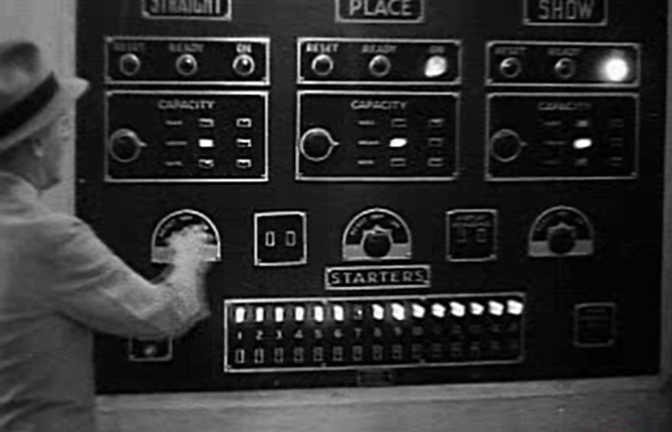
The image above shows a Julius Tote Control Room Switchboard at Hialeah Racecourse Miami, in the United States of America. Although the image above is low resolution, I think it is better than having no image at all. Along the top edge of the image above, there are three signs above the corresponding pool related equipment, that read STRAIGHT, PLACE and SHOW. Below each of these pool names is a panel with three lights labelled RESET, READY and ON. It can be seen that in the left hand panel of this three, there is no light illuminated and the two panels on the right have the ON light illuminated, indicating that the totalisator is on-line or in other words the betting is on for those two pools which are Place and Show.
The next three panels in the Control Room Switchboard shown above, below the last three panels, are the capacity setting indicator panels for each pool, each with the word CAPACITY at the top of them. They consist of two columns of three lights each. The left hand column are the request lights from the Control Room and the right hand column are the response lights from the Machine Room, where the mainframe equipment is located. In each column there will only be one light lit at any time. The three rows of of two lights are labelled on the left hand side, with the words forming the left hand column. At the low resolution of the original of this image the words are not close to being legible however the vertical column lights are the MAX MEAN and MIN lights of the Capacity Circuit described in the paragraphs above titled CAPACITY SIGNAL CIRCUIT./ Drawing NO. 3487.
At the bottom of the control panel the starters lights and switches can be seen. These switches allow the actual runners in the race to be configured. These switches enable the shaft adders, the subject of this page, which are required for the current race, to total investments during the betting period. Conversely the shaft adders which are associated with runner numbers that are higher than the maximum number of runners in the current race, or that have been scratched are disabled by these switches so that no erroneous registrations can be made. From this panel it can be determined that the system has been configured for a field size of fifteen and runner seven has been scratched as the number seven light is extinguished. In other words the adders for runners above fifteen and runner seven have been disabled. This circuitry is described above under the heading ESCAPEMENT ALARM & STARTERS LAMPS/ CIRCUITS / Drawing NO. 3486 and the sub heading Starters Lamps.
The knob the man has his hand on in the image above is the betting control knob, of which there are three one for each pool. The image above is a frame from a film, and in this scene from the film, the man is turning the betting off. As can be seen in the image above, he has already turned it off for the STRAIGHT pool at the beginning of this scene, as its associated ON light is not illuminated, as seen in the second panel above the switch he is holding. This action effectively disables all the Adders associated with the pool that the knob controls, in this case the STRAIGHT pool adders have already been disabled. Watching the video clip from which the above image is extracted, he then proceeds to turn the betting off for the PLACE pool and the SHOW pool by rotating the associated knobs anticlockwise which turns off their associated ON lights, which are illuminated in the image above. As it is not possible to read the writing on the knob positions of which there seem to be four, I suspect the right hand, or furthest clockwise position of the knob, is the ON position. Obviously one of the remaining three positions will be the OFF position and a second could be RESET. As the READY signal comes from the Machine Room, there will be no switch position for that in the Control Room, leaving it unknown what the fourth position of these knobs are.
This film clip can be seen by clicking on the image at the top of this page to return to the Photo Gallery, then scrolling down to the end of the page and selecting the Go to the index button in the Nav Bar at the bottom. Then select the Video clips of a working Julius tote chapter in the Thirdly section of the index. This video clip is titled hialeah1932.wmv (18.3Mb)Opening Day Hialeah Park 1932 and is the last in the index of video clips.
An adder from the Randwick Tote
I have included the image above as an example of an older architecture adder to those discussed above. The major difference between this adder and the previously shown ones is that this one pre-dates George Julius' invention of the first odds calculator in 1927. Prior to displaying odds, the Julius Totes displayed the total investments on each runner on each pool, as well as the pool grand totals. During that period of displaying total investments rather than odds, the runner total or grand total counter wheels, which constituted the public display board, were built into each adder. The Adders of that time were mounted in close proximity to each other, on the side of an outside wall in the machine room, so they could be seen by the punters on the outside. There were slot-like windows in the outside indicator wall of the machine room through which the drum wheel numbers at the front of the drum counter wheels could be seen. The image above shows one of the adders that belonged to what George Julius refers to as the large machine installed at Randwick and the adder he calls a horse counter or numerator. This system was installed at Randwick racecourse in Sydney in 1917 and at that time, the Randwick system was the largest automatic totalisator in the world. The forty sets of escapements and epicyclic gears arranged in four groups of ten, which George mentions in a white paper he presented to the Institution of Engineers Australia in 1920, are clearly visible in this image. Two of these groups of ten adding shafts run along the complete front of the adder at the bottom of the image. Two more of these shafts can be seen one behind the other on the right hand half of the adder towards the rear near the large counter wheel display drum.
Figure 9
Figure 9 above and the following paragraphs are extracts from a white paper presented to the Institution of Engineers Australia on Thursday May 13th 1920 by George Alfred Julius - Member. I will take this opportunity to mention that George was an instrumental founder and President of the Institution of Engineers Australia. I have provided this second copy of Figure 9 in this page as it is pertinent to the extract from the white paper following:
At this point a number of difficulties arise. Firstly, it would be manifestly impossible to accurately rotate these gears by means of the impulses received from the ticket-selling machines. Not only would the power required be excessive and the mechanism very complicated, but the "backlash" in a train of gears such as that described would give rise to endless inaccuracies. "Power" has therefore to be applied to move the gears, and to be so arranged that the issue of tickets on the various ticket issuers controls the extent of the movement.
In the earlier machines the counters or numerators were driven by heavy weights, and these weights also acted upon the train of epicyclic gears, causing these gears to move when they were allowed to do so by the sending of the records through from the ticket issuers. This arrangement, however, gave rise to great difficulties, and was found to be only applicable to relatively small machines. It has, in fact, since been entirely abandoned for all types. It will be remembered that the rate at which the counters would be required to "record" if direct connected to the ticket-selling machine might vary from "nothing" at one instant to a rate of several thousands a minute at the next instant, and it is impracticable to construct counter wheels 2 feet in diameter to stand such treatment.
The epicyclic gears, however, must obviously respond instantly to the records transmitted through them. Thus, if fifty clerks simultaneously issue tickets on the same horse, the records of those sales must instantly be picked up by the epicyclic gears, and as the large counter wheels cannot instantly respond to this demand some form of "storage" gear has to be introduced between the epicyclic gears and the counters to "store" up the records until the counters can he brought up to the necessary speed to record the sales. But this alone would not be sufficient, because if a form of storage gear was put in to merely allow the counter to get up to speed, then if at one instant tickets were passing at the rate of, say, 2,000 a minute on a horse, and at the next instant the issue of tickets ceased, the counters would work up to their speed of 2,000 a minute, and then required to stop dead when running at top speed. Such an arrangement would be obviously impracticable, and the goal has therefore to be so designed as to allow of, firstly, the instantaneous response of the epicyclic gear to the demands made upon it; secondly, the storage of these impulses during such time as the speed of the counters is being brought up to meet the requirements; and, thirdly, the gradual slowing down of the counter as it overtakes the registration of the stored-up records.
In other words, the mechanism that stores up the records has to control a variable speed gear, which will as required gradually speed up or gradually retard the counters, and so avoid all shock to the mechanism.
In the original designs the issue of all tickets of every denomination whether 10s., £1, £5, or £10, were transmitted to the unit wheel of the counters or numerators. This, however necessitated a very high speed of operation for the unit wheel, because although each unit bet only required one-tenth of a revolution of this wheel, each £10 ticket required two complete revolutions and in a machine of this type and of relatively small capacity, the speed of the unit wheel frequently reached speeds as high as 200 revolutions a minute. As it was obvious also that tickets of a denomination higher than £10 would be required, and even possibly as high as £1000 it was apparent that the practice of passing all registrations through the unit wheel would have to be abandoned.
In the latest type, therefore, only the 10s. and £1 registrations pass through the unit wheel. The £5 and £10 registrations are passed direct to the 10's wheels, the £50 and £100 direct to the 100's wheel, and so on. This, again, required some special design, because the 10's wheel had to record not only the 10's carried forward from the additions of records from the 10s. and £1 issuers, but also had to register the direct issue of £5 and £10 tickets, and similarly for the 100's wheel.
It will also be remembered that in describing mechanical systems of numeration, it was pointed out that the only satisfactory form of counter was one in which the various wheels moved instantaneously to the required position. Thus the 10's wheel would be required to move one division at the instant that the, unit wheel moved from 9 to 0.
With counter wheels of 18 inches or 2 feet diameter, and with a unit wheel revolving at a high speed, it is impossible to make the units wheel pick up and move the 10's wheel forward at the right instant without excessive shock, and in all these large high-speed counters, therefore, the 10's wheel has to be operated by, "relay " controlled by the movement of the unit wheel, but so designed that the 10's wheel and the wheels of higher denomination move forward without shock. The foregoing conditions have been met, in the following way :-
The epicyclic gears are made as light as possible, and are urged forward by " coil springs " and not by "weights." This ensured the instantaneous response of the epicyclic gears to the demands of the ticket-sellers. The movement of these gears so obtained is transferred to a " storage " screw which serves two functions, firstly, that when the machine is at rest it locks the driving gear which operates the counter wheels, and, secondly that when issues are to be recorded, it stores-up the records until they are registered by the counters. Immediately the tickets are issued the epicyclic gears instantly operate, being driven by the coil spring, and in so doing they turn the screw which then unlocks the driving gear for the counter, and the counter begins to operate. In so operating, this driving gear also moves a nut, which, acting on the storage screw, tends to bring it back to its normal position of rest, and thus again lock the counter driving mechanism. Thus the epicyclic gears in picking up impulses received from the ticket-sellers move the screw backwards, and the, driving gear of the counter is always trying to overtake this movement and thus return the screw to its normal position.
That is the end of the white paper extract. I have not gone further into these older adders or the "storage" screw George mentions, which is a mechanical form of memory that is a masterpiece of mechanical engineering in itself. For more information on these older adders, the whole transcript of George Julius' white paper that relates to the Julius Tote can be read in the Mechanical Aids to Calculation chapter of this website. To read this, click on the image at the top of this page, scroll down to the bottom of the page and select the Go to the index button in the navigation bar and then select the Mechanical Aids to Calculation chapter in the Firstly section. As George has placed quotation marks around the word storage, I will mention that I have contemplated that his use of the word storage is possibly the first time this word has been used to imply artificial memory!
Longchamps A Large System Adder
On the principle of ending with a bang, I have included the image above of the largest Adder I am aware of. It belonged to the second largest Julius Tote that I know of, which was installed at Longchamps in Paris in 1928. I have included it for visual effect and to convey how large Julius Tote Adders became. The Longchamps Julius Totalisator operated for 45 years before being replaced by a digital computer based totalisator system. Having mentioned above that the Randwick Julius Tote system was the largest automatic totalisator in the world, the Julius Totalisator system in Bombay later took this title and in turn later lost it to the Longchamps Julius Totalisator. As George has referred to the "storage" screw above the image of the Adder above, I will mention that these storage screws are visible in the image above. There are seven tubular devices clearly visible in the adder above, running from the rear of the adder towards the front, underneath the horizontal bridge of equipment above. Another one can be seen horizontally across the top of the Adder, which is sitting on the horizontal bridge and these tubular devices are the Storage Screws. There is another page in the Photo Gallery of this website dedicated to this image and the storage screws are described there amongst other aspects of the adder. To read this, click on the image at the top of this page, scroll up in the Photo Gallery index to the heading starting with the text Longchamps Paris 1928 - The World's Biggest Tote and then select the image thumbnail below with the first sentence of the associated text being One of the many electromechanical shaft adders at Longchamps.
The complete text from the company document titled Automatic Totalisators Limited Description of Electrical Circuit Diagrams can be read in another page in the Photo Gallery of this website. To read this, click on the image at the top of this page, scroll down to the bottom of the page and select the Next page button in the Navigation Bar. Scroll down in the Photo Gallery index to the heading Figures from George Julius' White Paper 1920 and a Julius Tote Engineering Drawing and then select the blue image thumbnail below with the first sentence of the associated text being This is a technical drawing showing Julius Tote interconnections.
- Thanks to Prof Bob Doran, for providing a major source of technical information contained in a collection of images of photographs he took of documents he found at Riccarton Racecourse. Presented in this page are extracts from a document Bob provided titled Automatic Totalisators Limited Description of Electrical Circuit Diagrams along with a blueprint engineering drawing of titled Julius Poole and Gibson blueprint.
- Thanks to Bob Moran for having drawn the 10 register schematic diagram and allowing me to present it in this page.
- Thanks to Neville Mitchell for providing the image of the 3 shaft adder at the top of this page.

Comments and suggestions welcome to totehis@hotmail.com 
The following page accessible via the Next page button below, contains relevant extracts from the company document titled Automatic Totalisators Limited Description of Electrical Circuit Diagrams dated 15/5/1935 related to the Julius Tote front end system, which was based on devices called Scanners or Distributors, which performed Time Division Multiplexing.
The previous page, accessible via the Previous page button below, which contains extracts from the company document titled Automatic Totalisators Limited Description of Electrical Circuit Diagrams dated 15/5/1935, relating to the TIMs (Ticket Issuing Machines.)