More after the Image...
Click on the image to go back to the photo gallery
If you arrived from navigating the website, use the navigation bar at the bottom of this page.
This is an Automatic Totalisators Limited Photograph
Copyright © 2014 Email - totehis@hotmail.com
This image shows the business end of a totalisator system. It is outside the windows where these machines were in operation that the punters queued up to lay their bets on the totalisator.
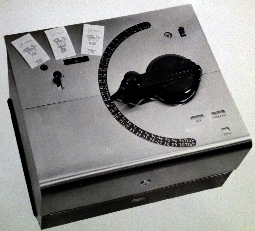
This is an image of a J8 TIM (Ticket Issuing Machine). This is a later model to the ones I am familiar with as it supports the Forecast pool as well as the Win and Place pools. The J8 is a significant machine as it probably had one of the longest lifespans of any of the TIMs manufactured by Automatic Totalisators. I remember them well as my PDP 11 tote systems with their J22 TIMs, replaced the Julius totes on the Brisbane tracks, which were predominantly using the J8 TIMs. Win-Place only versions of this machine were strewn all around the tracks that I worked on. In many locations around the tracks they remained, in no longer required locations, for at least a decade after their last operation, some lingered a lot longer.
More after the Image...
Click on the image to go back to the photo gallery
If you arrived from navigating the website, use the navigation bar at the bottom of this page.
This is an Automatic Totalisators Limited Photograph
Following is a comment made in 1999, from Joe Brandon, who worked for Autotote, which was Automatic Totalisators Limited's American subsidiary, in which he mentions the J8. I started with Autotote in 1974 at Dania Jai Alai. Ted Taylor (from London) was my boss. I cut my teeth on the J8. I'm now the manager at Atlantic City. Additionally Joe made the following observation in January 2015 relating to some tools, which he used to perform maintenance operations on the J8s: While looking at the J8 in the photo Gallery, it occurred to me I still have my latch up wrenches as well as my original ball peen hammer and punch (for replacing platen pins). The wrenches had to be thin to adjust under the halo. The Halo that Joe refers to is an arc of electrical contacts that sits under the graduated arc on top of the machine. The Horse Halo can be seen in the image below titled The bottom of a J7 TIM (Issuer) Showing the Horse Halo. It can also be seen in the circuit diagram in the first image below near the bottom to the right of centre where it is blatantly obvious and is labelled Horse Selector Quadrant.
Additionally, in 2015, Joe related how the J8 featured in his meeting Sue, his wife to be. He wrote The story is kind of legend here especially with old Autotote folks and I agree, it is the stuff of legends. Joe's anecdote:
One story I never told you and it has to do with the J8 and how I met my wife. We were installing Miami Jai Alai in 1974. At that time, we had designed what we called a black box which allowed us to interface the J8 in combination with the J11's to our PDP8 computer system and this was the first time we used the configuration. I rewired the plant with Don Raison's son Geoff. After setting up the line right outside the computer room, I was told opening night I would in fact be running the lines in what was called the TV room which was to the right and behind the court.
Now of course, you know what a J8 looks like and on our stands it sat about 3 1/2 feet high or so. When I walked into the room that night there was a young lady selling at the first machine. Let's say she was well endowed to say the least and those puppies were just resting happily and covering half of the top of the J8. Suffice to say I didn't wander far that night and Sue and I are now married, almost 40 years now. True story! If it wasn't for Autotote, I wouldn't have her, that's for sure.
Joe adds the following regarding his wife Sue, She is part of the history in more ways than one because she ended up being one of the greats, as to TIM technicians we had at the other company. Worked for them for over twenty years with me and actually worked her way up to running the Tote at Freehold when I took over the Atlantic City hub. She is actually in charge of our Maintenance Department here in Las Vegas now.
Joe also mentions a type of J8 that must have looked impressive. I'm trying to locate an old picture of me with a J8 back in "74". I hope I can find it because that particular machine was part of a shipment we received, I believe from South Africa at Ft. Pierce Jai Alai the year it opened. The really interesting part is the frames on those machines were brass instead of cast iron.
Joe also provides an interesting insight into dealing with problems on an electromechanical Julius Tote: One good memory of the electro mechanical system. At Ft. Pierce, the WPS, Quin and Exacta were belt driven with the brushes rotating on the commutator as the wagers came in. If the belt broke, especially at Jai Alai, you didn't stop to change the belt. You used your finger to rotate the brush until wagering stopped then you had about 20 minutes to change the belt. Note: WPS is Win Place and Show pools.
I mentioned Graeme Twycross' observation in the Melbourne Cup chapter of this website, about ATL's obtuse concept of portable, to Joe. Graeme stated that ATL would attach handles to anything regardless of weight, to classify it as portable. I also informed Joe that if I had to move a J22, during the period that I worked with them, mainly during the 1980s, I would get someone else to take the second handle. If I did move one on my own it was only a short distance. Joe replied with the following paragraphs:
Man, those J8s were heavy! 85lbs. if I remember right. But there was a heavier one than that. I believe we put the first computer system into Roosevelt Raceway ("59" I think?). It was DEC's first computer as used by us. Webmaster's Note: ("59" I think?) probably should be 1969 as the first DEC (Digital Equipment Corporation) based tote we developed was in 1968. After that meet, there was litigation of some sort (between DEC and ATL), of which I never knew the details per say. Anyway, I was sent to the Wilmington office in I believe "76" or so, give or take a year and while there, was assigned to help pull out of storage something called the J10. It was like a J8, frame wise, but bigger and had push buttons on the right and telephone relays mounted inside (I think I'm right on this. Memory gets fuzzy sometimes). They had just been released in conjunction with the litigation I mentioned above, I believe because it was proven they were definitely developed by Automatic Totalisators.
We actually converted them to be used on the PDP8 system with the same relays as we used in the J11. Anyway, those things were even heavier than a J8, if one can believe that! Somewhere around 97lbs. or so.
I was actually working in the shop when they pulled out the J10's. Heavy as hell as he stated. One funny thing occurred when one of the techs. I believe it was Sam Abelman opened the first one and a mouse jumped out. Scared the hell out of him. I remember they had a cage or box inside with old telephone relays like what we used in our old lampboxes. If memory serves, we replaced that with a relay rack something like the J11s. I believe these went to a track somewhere in the Caribbean Islands.
When I started in Feb of 74, Ted was the manager at Dania Jai Alai. He also managed Rocky Mountain Dog Track, Sodrac Park and Jefferson dog tracks. At the time Jean Melanson was the manager at Miami Jai Alai and Don Raison was the head of Field ops. We also had a French Canadian named Mel Parsons who ran tracks up in Northern Canada and Burl Knopp who managed the old Key West J8 installation. Ted was already an old timer when I came along.
Finally, a contemporary note from Joe relating what he is up to in 2015:
I'm still in the business. I left Autotote/Sci-Games ten years ago and I'm now running the tote for Las Vegas Dissemination. It's basically the same system I've been working on forever. The company started out as Autotote CBS and then went private. The owner is the son of the owner of a major casino here who actually at one time owned all the Coast properties. Even cooler, I was able to slip right in as we bought the license to 3 systems from Autotote so I'm really at home with it. We also have 4 programmers here who were with the other company to boot.
It is interesting to note that The Royal Turf Club of Thailand continued to use the electromechanical Julius J8s as the on-course ticket issuing machine up until October 1995, 3 decades after the advent of the electronic computer totes. Manufacturing of the J8 started in 1945 at ATL's Chalmers Street Factory and continued at the Meadowbank factory when it opened in 1947. This means the The Royal Turf Club of Thailand was still using this type of TIM half a century after they first went into production. They were a very good design!
I only worked on the electronic generations of totalisators so I have no experience with the electromechanical ones. Despite this, from my experience the J8 is probably the most iconic and famous of all the TIMs. I have had large numbers of tote operations staff work for me and met many others from different states. It is amazing how, when talking to sellers with long service, their face lights up, and they become animated, when recalling their early years working with the J8.
The TIM has an arc on the top, graduated with runner numbers. To select a runner number the handle is rotated to the desired runner number or combination for the Forecast pool and the knob on the handle is moved outwards to select the win pool or inwards to select the Place or Forecast pools. In this inward position another knob on the top of the machine to the left of the arc, labelled P and F selects the Place or Forecast pools. When the selection is complete the knob on the handle is pushed down initiating a transaction cycle and the handle is locked for the duration of the cycle. On completion of the transaction cycle the handle is unlocked so the next customer can be served. At the top right of the machine, there is an on off switch and to the left of that a handle release button. The handle release button is used if, due to some fault condition, the transaction cycle does not complete properly leaving the handle permanently locked. The Handle Release, Double Pole Switch is mentioned in the table below titled Sequence of Operations & Parts Fitted. Three sample tickets are visible on top of the machine, above the ticket chute from whence they were issued. All three tickets are Race 6 costing 5 Shillings with the left one being on the Win pool on runner 13, the middle on the Forecast pool on combination 3 and 4, and the right hand ticket the Place pool on runner 4. Down the bottom right corner of the machine are three ticket counters for Win, Forecast and Total.
Following are some observations regarding the J8 TIM from Chris Robertson, the most informed punter on the subject of totalisator systems I know. He refers to me not having seen a J8 in operation, despite my having worked on the system that replaced them:
You really missed something there! A house full of J8 machines flat out was something to behold - and to hear. The depressing and release of the issue button had a sound of its own (clackety-clack), and when a whole bank was in action there was plenty of sound. Swinging the machine's dial looked a lot more fun than pushing buttons on the J10.
An interesting place to watch the J8 in action was at Ireland's greyhound tracks. The machines were configured to sell win, place and forecast (exacta) at all windows. This could be done because, as in the U.K., Irish greyhound field sizes were limited to six runners. The first six positions on the dial's arc were occupied by the numbers 1 through 6, and the next fifteen by the various possible combinations, starting with 1-2, 1-3, 1-4, 1-5, 1-6, 2-3, 2-4 and so on. If the customer wanted a forecast with the higher number winning, the button was depressed in the 'place' mode. A boxed combination was sold as an 'each way' bet. I saw the J8 at Cork, Waterford and Dublin's Shelbourne Park; while earlier Julius machines were in action at Dublin's Harold's Cross (as at London's White City). This was way back in 1979.
My J8 Ticket Issuing Machine pamphlet gives the following information regarding pools.
POOLS
The different combinations of pools that can be operated from a J8 Ticket Issuing Machine are:--
This section contains extracts from a company document titled Automatic Totalisators Limited Description of Electrical Circuit Diagrams dated 15/5/1935. This document was kindly provided by emeritus Prof. Bob Doran who photographed the document when he was researching the Julius Totalisator, which was still present at Riccarton Racecourse in Christchurch New Zealand. Note that this old document calls the scanners distributors and the TIMs are called Issuers. The complete transcript of this document, from the images of it that Bob sent, can be read in another page in the Photo Gallery of this website. To read this, click on the image at the top of this page, scroll up in the Photo Gallery index to the heading Early Factory Images and then select the blue image thumbnail above with the first sentence of the associated text being This is a technical drawing showing Julius Tote interconnections. Additionally the drawings and lists presented below are extracted from a 55 page Automatic Totalisators Limited document detailing the assembly, wiring and test procedure for J8 Tims for Randall Park in Ohio, which mentions the year 1950. Essentially machines for America differed from those used in Australia in that they supported an additional pool called Show. Also as the Randall Park system installation was in 1950, by then the TIMs had a high or low value selectable on them.
Another significant difference between these J8s is in the runner selection. In the image at the top of this page, the runner selection arc that the runner selection handle sweeps around, is graduated up to runner 30 for the Win and Place Pools. Alternatively it can be used for the Forecast Pool with races having up to 6 runners. This was not the case with the TIMs for Randall Park where the arc was divided up into two halves. As can be seen from the Issuer Specifications presented below, the maximum number of starters supported is 12. This makes it possible to divide the runner selection arc in two. The top part of the arc is used as normal for selecting runners 1 to 12 for the Win and Place pools. This frees up the lower part of the arc for selecting runners 1 to 12 for the additional Show Pool. The Show Pool runners can be seen in the lower half of the arc in the drawing below labelled J8 OPER NO. 34 Randall Park. The word SHOW appears above this group of runners with an arrow pointing down towards the runners. Also the words WIN PLACE are above the word SHOW with an arrow pointing up towards the Win/Place runner selections up to 12.
Following is a collection of extracts of things Neville Mitchell, a long serving ATL Manager and Engineer said about the J8 and Randall Park, extracted from the Memories of the factory continued chapter of this website:
The wonderful J8 machine. I have no idea of how many they manufactured, but it was certainly in the tens of thousands. In late 1945, the company started in earnest to design totalizator equipment for post war use and, at this time, the J8 ticket issuing machine was born. The first batch of J8 Win, Place ticket issuing machines was installed on Randwick Race Course in 1948. The delivery of these ticket issuing machines to Randwick released a quantity of the existing J6 ticket issuing machines for despatch, along with some 2-shaft adding units, to the United States for use at Randall Park Racetrack. This was a stop gap move and in 1950 the company installed new equipment on this racetrack. That same year an associate company, Automatic Totalisators (U.S.A.) Ltd. was formed to purchase equipment from the parent company and lease it to racetrack operations in the U.S.A. This Company became a subsidiary and by 1967 the company had 23 operations in the United States and Canada. Up until October 1995, The Royal Turf Club of Thailand continued to use J8s as the on-course ticket issuing machine.
The drawing shown in the image below titled J8 OPER NO. 7 Randall Park has 7 inside a rectangle in the bottom right corner of the drawing titled OPER NO which is embedded in the name I have attributed to this image and all other similar images. It also has G.A.J. on the PART NO. line. G.A.J are George Alfred Julius' initials. Additionally in this identification rectangle titled AUTOMATIC TOTALISATORS OPERATION SCHEDULE at the bottom right hand side of the drawing, the draughtsman's name Noble can be seen to the right of the word DRAWN. This is Norm Noble, a long serving Automatic Totalisators employee. I remember him very well. He was a very charismatic character and although it was not his responsibility to do so I could always rely on him as a last resort to go to work in Sydney on weekends, public holidays, or otherwise out of hours to send me anything I needed in Brisbane. There is a photo of the ATL drawing office in the "Memories of the Factory" chapter that pre-dates my time which has Norm Noble in it, unfortunately he is facing away from the camera. You may have noticed, however Norm has also checked his own drawing as in the CHECK box below the DRAWN box, are the initials N.N. which belong to Norm Noble!
As these drawings relate to the Randall Park J8 TIMs, I have included the following extract from Rod Richards recollections of working at the Meadowbank Factory. Rod worked for Automatic Totalisators Limited as an apprentice and later an engineer in the late 1940s and early 1950s. Following is the extract:
On my first day at ATL I was introduced to man in charge of the Adders, Fred James an old Tote man whose first words were 'Rod, I do not care how long it takes, but it must be done right' I still remember those words as I still tend not to take short cuts. Although 'take your time' was not quite right as Totes was at the time super busy with a number of jobs in the pipe line and overtime being worked. I recall that towards the end of the year 1949, the Randall Park job in the USA was top priority as it had to be completed before a certain date to meet the racing carnival or severe penalties would apply, I think we even worked Boxing Day and air freight was involved.
The tables and all the drawings below come from a fifty five page Automatic Totalisators Limited document with the following information on the first page.
DATE : 12.9.50.
Note the archaic spelling of issuing above. Additionally, I find it interesting that Automatic Totalisators Limited issued documents to particular staff members. In the above case S. Huss from the Assembly Section. These were usually well presented booklets having a substantial cover, with the employee's name on it. I had an old company manual in one of my desk drawers at work in my office in the Old Main Tote House at Eagle Farm Racecourse for many years, which contained the tote maintenance area, the computer room and offices. The manual provided technical details related to a piece of equipment belonging to the Julius Tote era and was of no further value. The manual related to a product called Visitel, which was an electromechanical device that transferred writing on a transmitter unit which was printed on a receiver unit, both units being connected by electric cables. I kept the manual as I was impressed by the workmanship involved in producing it and that it demonstrated the principle of issuing manuals to specific employees, which I have never seen anywhere else. This manual was dedicated to Frank Ryan, who was the predecessor of the last Chief Engineer of the Brisbane Julius Totes, who I knew well, Charles Barton.
Finally, I find it quite amazing how so much was hand drawn prior to the advent of the CAD/CAM systems and finally the Personal Computer that put an end to the busy Drawing Offices producing all these drawings. I remember the impressive drawing offices at AWA (Amalgamated Wireless Australasia) where I worked in the North Ryde Factory and ATL (Automatic Totalisators Limited) in the Meadowbank Factory where I later worked. Neville Mitchell wrote the following which is set in the 1960s, in his memories of the Meadowbank Factory, which are contained in two chapters of this website: They put it together and they made the first basic computer tote system where they could go around to the people like the Hong Kong Jockey Club and say we are looking at computerised multi pool type systems and at that stage I was elevated to Drawing Office Manager. I was controlling 27 draughtsmen and trying to update the systems that were there so that we could cover larger projects.
On the second page of the General Assembly document, there is a drawing of the final product with the following specifications in the bottom right corner:
Issuer Specifications
Randall Park Installation
J8. Issuer
Two Stake $5 & $2
Three Pool Win. Place Show
Number of Starters-12
30 Horse Quadrant
Maximum No. of Races-10
Variable Code Wheels
Fixed Date
Wiring Diagram W275 & W276
Two Total "Electric" Veeders
Ribbon Colour - Blue
Test Coil Resistance - 58 Ohms
Trip Coil Setting - 1.2 Amp
Condenser 2N.20P.
Horse No. Type Leoo
This document has many pictures drawn of the J8 TIM in progressive stages of assembly starting with just the baseplate with four legs attached to it, to make access to the baseplate easy, raising it off the bench. This baseplate sitting on its legs, with a considerable level of assembly already performed can be seen in the drawing below titled J8 OPER NO. 7 Randall Park.
| 1 Type Wheel Peg & Frame | 23 Other Side of Issuer Wiring Former |
| 2 Type Wheel & Win, Place, Show Arm Assembly | 24 Selector Quadrant & Wiring |
| 3 Locking Rod Assembly & Ribbon Bracket | 25 Win, Place, Show Arm, Anchor & Spring. Show Switch Bumper Assembly. Pool Selection & Bracket. |
| 4 Intermediate Gear Bracket & Gear | 26 Condenser & Clips |
| 5 Handle Assembly. Handle Stop & Brush Holder | 27 Motor & Brushes, Chain & Split Link. |
| 6 Taper Pinning Operation | 28 Ribbon Feeding Operation |
| 7 Platen Assembly | 29 Issuer Box & Hinge &Wiring Clips |
| 8 Win Place, Switch Assembly & Slide Rod | 30 Plastic Issuer Handle , Pin & Circlip |
| 9 Paper Feeding Assembly | 31 Electrical Setting Details |
| 10 Trip Coil Assembly | 32 First Test |
| 11 Ribbon Rewind | 33 Taper Pinning Operation |
| 12 Quadrant Supports, Issuer lifting Handle & Posts & Cover posts | 33A Ticket Issuer Chute |
| 13 Handle Release, Double Pole Switch & posts, Test Switch, Handle Release Lever & Spring | 34 Covers & Horse Number Segments. |
| 14 Test Coils, Wiring Brackets & Cover Catches | 35 Final Test |
| 15 Latch switch & Show switch | 36 Spray Finish issuer Box. |
| 16 Cam operated Counter switch | 37 Attach Nameplate |
| 17 Guillotine Lever, Anchor & Spring Printing Lever, Anchor & Spring | 38 Clean & Inspect Box |
| 18 Value Slide Lever & Spring | |
| 19 Rotary Switch, Retaining Posts & Value Leaf Switch Assembly | |
| 20 Value Release & Spring | |
| 21 Veeder Assembly | |
| 22 Issuer Wiring Former & Brushes |
The image below has a title in the top right hand corner that reads: Internal Wiring for Two Stake Three Pool Issuer (W275). Actually, the title in the drawing has no L on the end of the word Pool, however I have corrected that in the title I have presented because I am sure it is not a Three Poo Issuer! Please excuse the jocularity, sometimes needed to lighten up the laborious task of wading through circuit diagrams and descriptions! This issuer is a Two Stake issuer as it has a value switch that can select one of two values for the transaction. The Rotary Value Switch can be seen in two parts on the left hand side of the drawing below. Up against the left hand edge of the drawing below there are two instances of the label consisting of the words Rotary on top of Value on top of Switch. The top instance of Rotary Value Switch is on the left hand side of the two arms of the switch, the top one labelled W for the Win Pool and the bottom one labelled P for the Place Pool. This part of the switch selects the appropriate connection pins in the 16 Point Plug shown top centre of the drawing below. The bottom instance of Rotary Value Switch is on the left hand side of another two arms of the switch, again the top arm for the Win Pool and the bottom for the Place Pool. This lower part of the switch selects the appropriate pair of contact arms in the semicircular device near the bottom, to the right of centre of the image below labelled Horse Selector Quadrant.
The circuit diagram shown in the image below has little circles I call pads, drawn in the conductor lines to represent joins. These pads all have numbers associated with them. These numbers relate to the wire numbers titled Wire No. in the table below titled General Assembly of Randall Park issuer Wiring Information.
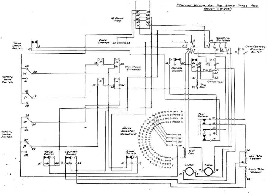
As mentioned, the Randall Park J8s accommodated the Show Pool. This is selected by an additional switch added to the J8. It can be seen in the Circuit Diagram above with the label Show Switch, which can be found to the left of the Horse Halo below the text Horse Selector Quadrant, which is synonymous with Horse Halo. The J8 at the top of this page, as previously mentioned supported an additional pool as well, to the normal Win and Place, only instead for the Show Pool it is the Forecast Pool. The switch seen in the top left quadrant of the J8 in the image at the top of this page, that is marked P at the top end of its travel and F at the bottom end of its travel, changes a Place Pool bet to a Forecast bet, if the switch is in the lower position. The Show Pool switch shown in the Circuit Diagram above, will have been implemented by the same switch as the one just described in the image at the top of the page, except that instead of F for Forecast it will have been marked S for Show.
Below and to the left of the 16 Point Plug in the Circuit Diagram above, is a coil winding with the label to the left of it reading Race on top of the word Change. The number on the left side of the coil reads 35 and on the right 43. This is the Race Change Coil. This coil activates the escapement rocker for the Race Change escapement wheel which rotates the Race Number Stamp to the next race to be run when required, so that the J8 prints the correct race number on the tickets. This Race Change escapement wheel can be seen in the image below titled J8 OPER NO. 7 Randall Park on the left hand side of the assembly labelled SAJ203. The Race Change escapement wheel and rocker is visible in the image near the bottom of this page titled J8 OPER NO. 31 Randall Park in box number 2, which shows the clearance required for the rocker. This sketch in box 2 does not show it, however the Race Change Coils of which there are two with a single winding are installed directly below the rocker in the sketch as the magnetic field the Race Change Coils generate operates the rocker. Following is an extract from a talk Neville Mitchell gave about the Julius Totes, which is presented in the The Premier Tote Operation 1930 + Neville's talk chapter of this website and the barrels he mentions which had 8 or 10 positions, have the race number stamps on them:
The other coil you will notice in the J8 is the race change. This is the same sort of set-up and it had a barrel, most of the barrels had 8 or 10 positions. It was a die cast aluminium barrel which had the numbers 1 to 8 or 1 to 10 on it and there was another barrel associated with that called the code barrel. These codes were kept secret and they were only issued out a few minutes before the first race at any race track and the code barrel was lined up in a special way. The mechanic in charge of the tote house would be given a box with all of the code barrels and race barrels in it. He would then open an envelope when he got to the tote house and it would tell him the code of the day so he knew which code on the barrel to start with. He inserted that and then wound the clockwork mechanism of the race change back to race one. At the end of race one, the race engineer, the person in charge, or the totalisator manager for the day, would call up a race change and a push-button was operated in the main control room, which caused all of the ticket machines to rotate to race two and consequently show not only the race number but the new code word.I think it was Ron Findlay, who was a technician with Automatic Totalisator Limited, who told me that when the current race number was incremented on the RDC (Race Day Control) console all the TIMs received the signal to rotate the race number barrel inside their printers and if you were in a tote house which had a significant number of machines in it, then it was quite impressive to hear them all clank in unison.
Below and to the right of the 16 Point Plug in the Circuit Diagram above, there is a group of three switches labelled Isolating Switches. To the left of these four switches is a fuse with the number 45 on top and the number 7 below. This fuse along with the three switches are located on a board of their own, which is connected to the bottom right hand side of the case on the inside. When the top of the J8 is lifted by the hand-grip at the back, it hinges open on the hinge seen running across the width of the front of the J8 at mid height level. This hinge can be seen in the image at the top of this page. This is the maintenance position of the machine exposing all the component parts and the switch and fuse board mentioned inside the case is easily accessible. The two right hand switches on this board control the power to the clutch and motor seen as two large circles in the bottom right quadrant of the Circuit Diagram above. The motor can be seen as the largest cylindrical object in the image below titled J8 OPER NO. 27 Randall Park . In the J8 in my collection this motor was manufactured by a sizeable Australian company called Airzone founded in 1926. The drive shaft out of the motor on the right hand side connects to the cylindrical magnetic clutch.
In the bottom right corner of the J8 TIM shown at the top of this page three counters can be seen marked WIN and FORECAST side by side, with another marked TOTAL underneath. These counters allowed the operator's takings to be balanced. These counters in the Randall Park J8s were electromechanical counters manufactured by Veeder Root. Veeder Root mechanical counters were also used in the Adders and the Australian J8 I have in my collection also has the mechanical counters. In the bottom right hand corner of the Circuit Diagram above, two windings can be seen, one on top of the other. These are the Veeder Root counter windings. Like the J8 TIM shown at the top of this page these counters total the number of sales on the American version of the J8, however instead of dividing the sales into Win/Place and Forecast pools like the Australian J8 shown at the top of this page, it divides them into high value and low value. The top of both windings, via pad 14, comes from the switch above and to the left of the counter windings with the word Test on top of the word Switch seen on top of the switch. This switch disconnects the counters from the Cam Operated Counter Switch when the Test Switch is activated, as test tickets are not part of the sales. The Cam Operated Counter Switch can be seen in the Circuit Diagram above near the top right hand corner with connecting pads labelled 5 and 13. The words constituting Cam Operated Counter Switch are very difficult to read even in the original document. They look to me like Cam Operated on top of the much clearer two words Counter on top of Switch. A few words are rather bizarre in the Circuit Diagram above, for instance in the word Operated, the "p" has no bottom half the "r" and "t" have no down stroke and the "d" has no upper half. Despite this I feel confident I have interpreted it correctly.
After having indicated my confidence in getting the name Cam Operated Counter Switch right, I have found absolute confirmation that my interpretation is correct. The Cam Operated Counter Switch appears in the list above titled General Assembly of Randall Park issuer in item 16. Additionally the Cam Operated Counter Switch assembly can be seen in a picture drawn inside a circle titled Cam Operated on top of Counter Switch in the image below, titled J8 OPER NO. 22A Randall Park. The bottom ends of each Veeder Root winding at pads 21 and 29, have conductors attached to them both seen descending down to the bottom of the drawing and then travelling left both jumping up a step before travelling further left and finally rising vertically to join the two end pads of three belonging to the switch with a label on top consisting of the word Counter on top of the word Switch. I have called the little circular connection points on these old drawings pads, as this is what they were called on PCBs (Printed Circuit Boards) although the early Julius Totes pre-dated PCBs. This Counter Switch, switches the power supply which arrives at the circuit above via Pin 7 bottom right of the 16 Point Plug seen near the middle of the top of the drawing. From there a conductor is shown travelling right and then down to the bottom end of a fuse between the pads labelled 7 below and 45 above. From the upper pad 45 a conductor can be seen travelling up then left then down and left again and then through two more down and left steps finally connecting to the switch arm of the Counter Switch. Hence this Counter Switch selects either the upper or lower counter to receive power, which is the means of directing the high value transactions to the high value counter and the low value transactions to the low value counter. The labels to the right of the two Veeder Root windings again are hard to read and look like the word Low followed by something indeterminable, on top of Veeder for the upper winding and Highfollowed by something, on top of Veeder for the lower one. Both labels are located close to the right hand edge of the drawing near the bottom of the page. As previously mentioned, the bottom ends of each of the Veeder Root windings are at pads 21 and 29, which are connected to the left and right pads of the Counter Switch. We can now use the table below titled General Assembly of Randall Park issuer Wiring Information to look up what the names of the Veeder Root windings are. For pad 21 the table records the start as the Low Total Veeder and the end as the Low Counter Switch and for pad 29 the start is the High Total Veeder and the end is the High Counter Switch. We now know the names of the two Veeder Root windings in the Circuit Diagram above, which are shown in the diagram with the Low Total Veeder above the High Total Veeder.
Note that the Veeder Assembly is mentioned in the table above titled Sequence of Operations & Parts Fitted in item 21. The Veeders are also mentioned in the table below titled General Assembly of Randall Park issuer Wiring Information in items 14 21 and 29 as well as item T in the First Test listed below.
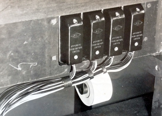
The image below shows the 16 Point Plug shown top centre in the Circuit Diagram above. The ATL diamond logo can be seen on each of these connectors in the image below, as well as the words Automatic on top of Totalisators on top of Limited below the diamond, on each of the connectors. Normally the plugs of this type of connector were connected to the TIMs and the Adders, and the cables emanating from the black plugs seen in the image below probably come from a TIM, as the J8 in my collection has four of these plugs mounted on the back of the case, which is out of view of the image at the top of this page, on the side facing the top left corner of the image. The sockets that the black plugs are plugged into in the image below, which look like they are permanently attached to a wooden cable tray, will have had cables connected to them inside the cable tray, which amongst other connections ran inside the cable tray to the Horse Units/Adders in the Machine Room with the scanners in the machine room providing the activation pulse for transaction cycles. Transaction cycles are performed by mechanical parts that interact with what is called the Betting Circuit. The part of the Betting Circuit that pertains to the TIMs, is described in the company document extracts below. It is interesting to note that the Circuit Diagram above only shows one of these 16 Point Plugs. The other three carry the connections from the contacts in the arcs of the Horse Halo in the Circuit Diagram above to the machine room. A discrepancy exists between my J8 and the Circuit Diagram above in that my J8 does not support two values and supports a maximum field size of 24, which means its Horse Halo has 48 contacts, 24 for the Win Pool and another 24 for the Place and 48 connections can be carried in three 16 pin plugs. This means the image of the plugs below was taken of a system that supported the type of J8 that I have in my collection. The roll of ticket paper seen sitting on a paper dispenser in the image below, confirms that the nearest TIM is not far away, probably on top of the bench vertically above. Below the ticket roll seems to be the floor level, the level at which the operator's feet will rest. Actually, I bet the odd operators foot has rested in the angled wooden support for the cable tray, seen at the right hand lower edge of the image above! The slot below the displayed tickets shown in the image at the top of this page, is where the tickets are ejected which are printed on and cut from the ticket paper like that shown on the roll in the image below.
Some Plastic Moulded ATL connectors
In the extract below titled BETTING CIRCUIT./ Drawing No. 3509., the first paragraph relates to the circuit through each horse unit. The Horse Unit in this old document is what is referred to in the rest of this website as one of the many Shaft Adders in a Julius Tote installation. These are an integral part of the mainframe. The escapements mentioned refer to the escapement shafts containing escapement mechanisms and escapement wheels that record transactions from the TIMs which are summed by epicyclic gears on the adding shafts on the adders. From a simplistic functional perspective, as opposed to implementation, I see the TIMs as the start of the BETTING CIRCUIT, as nothing happens on a Julius Tote except for the rumbling of the mainframe drive motors and scanner drive motors in the machine room, until someone buys a ticket, which is issued from the TIM. In this view, the end of the BETTING CIRCUIT is the Adders where the transaction is recorded and the bit in between is the Scanners/Distributors and associated equipment, which constitutes the front end system that interfaces the TIMs to the Adders.
Following are extracts, pertinent to the TIMs from the Automatic Totalisators Limited Description of Electrical Circuit Diagrams document.
The circuit through each horse unit is then as follows -. Through the Betting Circuit Switch and Fuse and through the normally closed contacts of the Escapement Cutout Relays (the operation and purpose of these relays is described elsewhere) to the common side of the escapement fuses, there being one fuse for each escapement and thence to the escapements.
From the escapements the circuit now proceeds to the corresponding contacts on the Horse Selector Segments of the corresponding issuers, that is the wire from No. 1 escapement on No. 1 Win Horse Unit is looped into the No. 1 Contact on the Win Horse Selector Segments of all issuers in No. 1 Group and so on.
Webmaster's notes
The image below is not part of the Description of Electrical Circuit Diagrams document.In the paragraph above, the Horse Selector Segments are mentioned. Although the following image shows the bottom of a J7 rather than a J8, they look similar. The arc seen with contact studs on it in the image below is the Horse Selector Segments or Horse Halo as it was later called and was used to select the runner number required for the transaction. The arm that sweeps across the arc, or Horse Halo, in the image below is connected to the runner selector handle seen on the top of the J8 in the image at the top of this page.The bottom of a J7 TIM (Issuer) Showing the Horse Halo
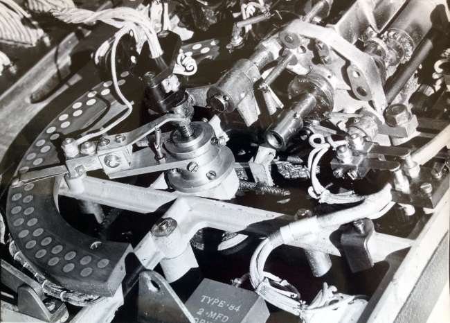
The collecting brush which picks up the contacts on the Horse Selector Segments is mentioned in the first paragraph of the continued document extract below and the collecting brush can be seen in the image above about half way around the horse halo. Here the extension of the runner selection handle, seen anchored in the centre of an imaginary circle created by extending the runner selection arc in the image at the top of this page is two metal strips in the image above each extending to a position above their respective arc of contacts, with a contact at the ends of each of the strips, which are the collecting brushes one for each of the two arcs of contacts. The outer arc of contacts are for the Win Pool and the inner arc of contacts are for the Place Pool. Usually, there are as many studs in each arc as the maximum number of runners in a race plus one for printing test tickets.
These collecting brushes are clearer in the image below as the Horse Halo has not yet been installed. They are described in the paragraph below the image below. There are four collecting brushes in that image as it relates to the American Randall Park J8s which supported two selectable values requiring an extra pair of Horse Halo studded arcs and corresponding brushes/contacts.
The circuit through each Issuer, in the first paragraph following these notes, extracted from the Automatic Totalisators Limited Description of Electrical Circuit Diagrams document, can be seen in the image labelled J8 Circuit Diagram Randall Park, above. When trying to match the technical descriptions in the Description of Electrical Circuit Diagrams document which was written in 1935 for a system in New Zealand, to the Circuit Diagram above, which shows the American J8 diagram of 1950, we have to consider that the fifteen years between them and the fact they are systems with differing requirements, make differences between the documents inevitable. In fact, as Neville Mitchell related, the J8 TIM only came into being in late 1945, so the TIM in use at Riccarton New Zealand being described in the 1935 company document will obviously be a prior model to the J8 TIM. A major difference between the two is that the American J8s supported a selectable value, a feature the New Zealand system TIMs and the J8 I have in my collection and any other Julius Tote TIM I have seen, did not have. As a consequence of differences, the sequence of the components in the description in the extract below does not line up with the Circuit Diagram above however the items in the list do match the items shown in the betting circuit in the Circuit Diagram above, all be it in a different sequence, so I have followed the sequence in the Circuit Diagram for the sake of my explanation. To begin tracing the Betting Circuit through the J8 in the Circuit Diagram above lets begin with the Collecting Brush where the description below begins. The Collecting Brush mentioned below is one of four seen in Diagram above at the tips of the arms radiating from the centre of the semicircle called the Horse Halo or Quadrant. At the centre of these radiating arms, the four conductors connect with four wires numbered 25 27 26 and 28. As mentioned, the description below relates to a system that does not have a selectable value on the J8, so it is describing a system that only has two of these contact arcs and only requires two wires to service the arcs. To emulate the system that is being described, let us just consider wires 25 and 27. These two wires in the drawing travel vertically downwards, represented by a single line that then turns left towards the left hand edge of the drawing then rises and connects with one of the two Rotary Value Switches. As we are only dealing with one pair of conductors coming from the Selection Brushes, these value switches do not exist in the J8 being described and we can accommodate that in this description by imagining that conductor 24 is directly connected to conductor 24 bypassing the switch and similarly conductor 27 is directly connected to conductor 22 again bypassing the switch. wires 27 and 22 now head right then rise to join the Win - Place Selector Switch mentioned in the description. One of these switches marked P on the left and W on the right will depend on which pool W for Win and P for Place by the runner selection handle knob. The Betting Circuit continues on wire 23 connected to the two inner contacts of the switches in the drawing that are shown joined together, heading right crossing several vertical wires finally turning upward to immediately join the Tip Coil mentioned in the description. After passing through the Trip Coil it rises again with wire 33 to join one of the Normally Closed (NC) contacts of the Trip Switch mentioned in the Electrical Circuit Diagrams description below. From there the Betting Circuit passes through the (NC) contacts of the Trip Switch and travels a short distance left with wire 44 to join the Handle Switch, which is called the Handle Lock Switch in the Electrical Circuit Diagrams description below. When the second contact of the Handle Lock Switch closes as well a connection with wire 16 on the left is made, as is the case during a transaction cycle and the Betting Circuit continues down, turns right and descends again to the bottom top contact of the (NC) pair of contacts at the bottom of the Test Switch. Finally, the Betting Circuit then passes through these test switch contacts and joins wire 17 which rises again in the Circuit Diagram above, turns left, crosses a couple of vertical conductors and then rises again past the Handle Switch on the right. It then turns left rises a small step and turns left again joining the left hand contact of a (NC) pair of contacts in the Value Latch Switch. Again, as the J8 being described in the Description of Electrical Circuit Diagrams document does not have the selectable value feature this switch does not exist in the J8 being described in the Electrical Circuit Diagrams document extract below so let us assume that wire 17 is connected to wire 3 which is seen heading right to join the bottom left contact of four in the Issuer Switch/Tumbler Switch mentioned in the Electrical Circuit Diagrams document extract below.
Having mentioned the Handle Lock Switch in the last paragraph, I will mention that this switch is arranged differently to all the others. The other switches that have three arms to them in the J8 Circuit Diagram Randall Park above, all have wires attached to all three arms, whilst the Handle Lock Switch shows no wire connected to its centre arm. All switches with three arms show the (NC) contacts of the switch, not only by showing these contacts in contact with each other, whilst the other pair of contacts are not drawn in contact with each other, but additionally by emphasising the contacts that are touching each other by being represented as filled in black triangles and the ones not touching each other being represented by outline triangles only identifying the Normally Open (NO) contacts. With all the other three arm switches in the Circuit Diagram above, when the switch is activated, the (NO) contacts close and the (NC) contacts open. This is not the case with the Handle Switch. This is the only three arm switch in this drawing that can have both sets of contacts closed at the same time, so when it is active wire 44 on the right is connected to wire 16 on the left through both pairs of closed contacts. This now gives us a switch, which can be closed by one pair of contacts by one source, and opened through the second pair of contacts from a separate source. The Handle Lock Switch can be seen in item number 10 in the image below titled J8 OPER NO. 31 Randall Park. Item 10 relates to two adjustments, the Trip Release Cam and the Safety Cam which relates to the lower sketch. The switch in this lower sketch is the Handle Lock Switch, and the centre arm of this switch is rigid as indicated by the thicker line in the sketch and the other two arms are flexible and are pushed to break contact in the case of the upper contacts and pushed to make contact in the case of the lower contacts. Herein is yet another oddity of this switch in that the end of the centre arm is bent upwards then backwards, making it possible to break the contacts by applying force towards the centre contact rather than making contact as is the case with the lower arm of the switch. A potential problem with this arrangement is that if the upper arm is pushed far enough, it will make contact with the lower arm and the switch will be erroneously closed again. This is the reason for the test in the second part of item 10 which reads: Rest Safety Cam lightly on Top Leaf. Ensure Contacts do not short when fully opened by Cam. Do not short, means that the top arm should not contact the middle arm otherwise a short circuit will be caused across them which is the same as the switch being closed rather than open. The (NC) contacts, which are the upper ones in Item 10 of the Handle Lock Switch are opened by what is referred to as the Safety Cam on the Printer Drive Shaft, which when at rest leaves these contacts closed. This Safety Cam rotates clockwise in the direction of the arrowhead arc in the sketch and when it has rotated approximately 280 degrees it will open the contacts, with the Cam's projection on the right hand side of the fulcrum rather than the left and they remain open for most of the remainder of the Cam's 360 degree cycle with the contacts closing again shortly before the Cam comes to rest. I presume this Cam is called the Safety Cam as opening the Handle Lock Switch is a last ditch effort to break the Transaction Circuit if the normal method fails as this would have the potential to disrupt this TIM's Scanner and consequently all the other TIMs in the same group. The (NO) contacts of the Handle Lock Switch are closed by the knob on top of the runner selection arm. When this knob is pushed down and latched in place, indicating a sale and initiating a transaction cycle when the J8 is scanned, the (NO) contacts of the Handle Lock Switch are closed as well.
The circuit through each Issuer is then as follows. From the collecting brush which picks up the contacts on the Horse Selector Segments through the Handle Lock Switch (closed only when the handle is locked down) through the Trip Coil, through the trip switch (normally closed when the Issuer is stationary), through the Issuer Switch (Tumbler Switch on Issuer Cover Plate) to the Win - Place Selector Switch.
From each Issuer two wires (one for Win and one for Place) are taken from the Contacts of the Win-Place Selector Switch to the Double Pole Issuer Common Switches on the bottom of the Distributor and Relay Switchboard and thence through the coils of the corresponding Relays to the Distributor Contacts. There are a pair of relays (one Win and one Place) for each Issuer and a pair of Distributors (one Win and one Place) for each Group of Issuers and each Distributor has 8 contacts corresponding to the 8 issuers in the group.
Webmaster's note: The following title is a list item extracted from the BETTING CIRCUIT./ Drawing No. 3509 section of the Description of Electrical Circuit Diagrams document.
RELAYS ON DISTRIBUTOR BOARD.
There are a pair of relays, one for Win and one for Place for each Issuer.
These relays serve to provide a definite time for the Issuer Trip Coil to function even if the Issuer Handle is depressed just as the Distributor Contact arm is leaving the Contact Stud corresponding to that Issuer.
The relay coil is connected in series with the Trip Coil and escapement magnets and so is energised when the Betting circuit is completed. The relay contacts are arranged so as to short circuit the distributor when the relay closes. Thus the Betting Circuit is maintained when the Distributor Contact arm leaves the contact stud and is only broken by the Issuer Trip Switch. The relay is very quick in operation and will close and so maintain the circuit if the Issuer Handle is depressed just as the Distributor Contact arm is leaving the contact stud.
As the distributors are an essential part of the Betting Circuit I have included another extract from the company document mentioned that gives an example of the path of the betting circuit which obviously includes the path through the distributors.
To illustrate the operation of the Betting Circuit more clearly, assume that No. 22 Issuer is to Issue a 'Win' Ticket on No. 3 horse. The circuit will then be as follows-
When the Issuer Handle is depressed therefore, the circuit is complete except through the Distributor which completes the circuit as soon as it reaches No. 2 stud. No. 22 Win Relay will then instantly close and so maintain the circuit. The bet will be registered No. 2 Escapement of the Win Grand Total Unit and No. 3 Win horse Unit and the Issuer Trip Coil will function to start the Issuer and open the Betting circuit again.
Here we take a break from the BETTING CIRCUIT./ Drawing No. 3509. extracts
In the image above, at the tip of the runner selection arm referred to above, the Win/Place selection switch activating arm can be seen protruding above the runner selection arm. The circular knob on top of the end of the runner selection arm, as seen in the image at the top of this page, can travel a short distance radially along the runner selection arm. This movement moves the switch arm shown in the image above. At the left hand end of its travel seen above, or outer position, it selects the Win Pool and at the right hand end of its as seen above, or its inner position it selects the Place Pool. The switches that implement this function can be seen in the circuit diagram above titled J8 Circuit Diagram Randall Park as a group of four switches arranged in the shape of a square slightly above and to the left of the centre of the diagram. The box is arranged as two rows of two switches each. The switches have letter between the contacts the top pair being P and W which is repeated for the second row. To the right of this group of switches is the label consisting of the words Win Place above Switches.
In the circuit descriptions above the image above, under the heading RELAYS ON DISTRIBUTOR BOARD extracted from the Description of Electrical Circuit Diagrams document, the Trip Switch and the Trip Coil are repeatedly mentioned. These can be seen in the drawing below inside two circles in the bottom half, Trip Coil Assembly on the left and Trip Coils on the right. The Trip Switch can be seen in the centre of the Trip Coil Assembly below with the springy metal strips containing the switch contacts at their tips, pointing downwards. The mechanism behind these metal strips pushes on the nearest of the metal strips in the switch which acts to close the contacts of the switch. The Trip Coil Assembly can also be seen in the drawing below titled J8 OPER NO. 27 Randall Park. It is located at the left rear of the partially assembled TIM, sitting higher than any other assembly in its vicinity. The Trip Switch breaks the Transaction Circuit at the end of a transaction cycle and starts the print cycle in the J8 to produce a corresponding ticket for the customer. In the J8 in my collection, once the trip coil has activated the solenoid to rotate the associated rocker arm, this action opens the normally closed contacts of the Trip Switch, which are for the Betting Circuit and closes the normally open contacts, which are for the magnetic clutch, activating the clutch which starts the printer drive shaft rotating powered by the motor through the clutch. A spring loaded locking lever which looks like it is called a Blade, latches the Trip Switch in this state, by engaging the rocker arm which keeps it in this position until the print cycle is complete. This activation of the Trip Switch marks the end of the transaction cycle and the beginning of the print cycle. After the best part of a revolution of the printer drive shaft, a cam on the drive shaft comes in contact with a flange on the Blade located at the opposite end of its fulcrum to where it is in contact with the Trip Switch rocker arm. The force applied by the cam rotates the Blade around its fulcrum, against the pressure of its spring holding it in place engaged with the notch in the rocker arm, rotating it away from the Trip Coil Rocker allowing the rocker arm spring to return the rocker arm to its rest position. This deactivation of the Trip Switch disengages the clutch, stopping rotation of the printer drive shaft and restores the betting circuit through the J8 ready for the next transaction when it is scanned again. By the time the Trip Switch is reset by the cam on the printer drive shaft, a similar cam on the same shaft oriented about 135 degrees in front of the first cam in the direction of rotation, has already released the Handle Lock mechanism. The Trip Coil, its Rocker and the Blade can be seen in box 6 of the image below near the bottom of this page titled J8 OPER NO. 31 Randall Park. The Rocker has a hole in its right hand end. This is for the spring that holds the rocker arm in its rest position whilst the Trip Coil is not creating a magnetic field. A small part of the Blade seen top left in box 6 is seen engaged with a notch in the rocker arm. The part of the Blade in view is just the tip of a much larger lever. The rocker arm is just short of 6.5 cm long and the Blade is 10 cm long.
The following table exists in the Randall Park document, however it has no title so I have made the following title up. It clarifies the numbers in this document like the ones seen identifying wires in the image below that have small circles around them and lines pointing to the particular wire in question. For instance, in the previous paragraph, I wrote The Trip Switch can be seen in the centre of the Trip Coil Assembly below. It is intuitive to think the Trip Switch is in the Trip Coil Assembly, however the table below provides proof positive. There is a line pointing to this switch inside the Trip Coil Assembly circle emanating from a position near the bottom left corner of the drawing where there are two small circles containing the numbers 34 and 44. Looking at the wiring table below these two numbers are both identified as the Trip Switch confirming the Trip Switch is part of the Trip Coil Assembly. Furthermore, the table below also informs us that the wire numbered 34 that is connected to the Trip Switch connects the Trip Switch which is in the Start column to the Condenser, which appears in the End column. Nowadays, Condensers are called a Capacitors. Similarly looking up the wire numbered 44 in the table below we find this connection goes from the Trip Switch shown in the Start column to the Handle Switch, which appears in the End column. These connections from the Trip Switch to the Condenser and the Handle Switch can be seen in the Circuit Diagram above labelled J8 Circuit Diagram Randall Park.
The wire numbers 34 and 44 already mentioned in the table below and the Trip Coil Assembly drawing shown bottom left of the drawing below titled J8 OPER NO. 22A Randall Park also apply in the circuit diagram mentioned above. This is because all three of these sources come from the Randall Park documentation. For the sake of this explanation, to pick an easily identifiable location on the circuit to start with, I will begin from another point that will lead us back to the Trip Switch, Handle Switch and the Condenser. We can see from the table below that wire number 31 goes from the Trip Switch to the Clutch. The Clutch is easily identifiable in the Circuit Diagram above titled J8 Circuit Diagram Randall Park. Near the bottom of this Circuit Diagram, there are two large circles drawn side by side, the left hand circle is the clutch. The wire number 31 mentioned is connected to the left side of the Clutch. It descends, travels right and rises vertically, then turning right again for a short distance then returning upwards past the mid height level of the drawing, finally turning left and connecting with pad on the right hand contact of a switch. The pair of contacts in this switch are shown in their open position as seen in the hollow triangles at the top of the switch arms. To the left of this is another switch with its contacts shown closed identified by the filled in black triangles at the top of the switch arms. This is the Trip Switch we are interested in. The left hand arm of this closed switch has two numbers on the right hand side of its connection pad which are 34 and 44, the numbers we were aiming to identify. We previously determined that conductor 34 connects the trip switch to the Condenser. We can now see this in the circuit diagram. Wire number 34 travels down from its connection pad in the left hand arm of the closed contacts of the Trip Switch and then turns right a short distance before descending slightly to join a pad also numbered 34 at the top of the Condenser the destination we were chasing. This condenser bears the conventional capacitor symbol which is two parallel lines that represent the electrodes, at right angles to the leads, although in this drawing the electrodes are shorter to what I am accustomed to. The Capacitor in the Circuit Diagram has the word Condenser underneath it. This wire number 34 in the J8 Circuit Diagram Randall Park drawing above, diagrammatically shows the connection shown in tabular form in the table below titled General Assembly of Randall Park issuer Wiring Information. It is now a simple matter to identify the wire number 44. Returning to the left hand arm of the closed contacts of the Trip Switch in the Circuit Diagram above, from the pad in the left hand arm with 44 to the right and above, this conductor travels left from the pad, which we previously followed the downward path. It travels left a short distance crossing two other vertical conductors and then joining a pad also numbered 44, which is in the right hand arm of another switch. This switch has the name Handle Switch below it.
| Wire No. | Start | End | Wire No. | Start | End |
|---|---|---|---|---|---|
| 1 | Tumbler Switch | Show Switch | 24 | Win Place Switch | Win Value Switch(Betting) |
| 2 | Tumbler Switch | 16 Point Plug | 25 | Low Win Value Switch | Low Win Brush Ring |
| 3 | Tumbler Switch | Value Latch Switch | 26 | High Win Value Switch | High Win Brush Ring |
| 4 | Tumbler Switch | Test Coil | 27 | Low Place Value Switch | Low Place Brush Ring |
| 5 | Tumbler Switch | Cam Op. Counter Switch | 28 | High Place Value Switch | High Place Brush Ring |
| 6 | Tumbler Switch | Trip Switch | 29 | High Total Veeder | High Counter Switch |
| 7 | Isolation Fuse | 16 Point Plug | 30 | Show Switch | Win Place Switch |
| 8 | Isolation Switch | Clutch | 31 | Trip Switch | Clutch |
| 10 | Test Switch | Isolation Switch | 32 | Trip Switch | Condenser |
| 12 | Motor | Isolation Switch | 33 | Trip Switch | Trip Coil |
| 13 | Test Switch | Cam Op. Counter Switch | 34 | Trip Switch | Condenser |
| 14 | Test Switch | Veeders (Common) | 35 | Race Change | 16 Point Plug |
| 15 | Show Value Switch | Show Switch | 36 | Show Value Switch | 16 Point Plug |
| 16 | Test Switch | Handle Switch | 37 | Show Value Switch | 16 Point Plug |
| 17 | Test Switch | Value Latch Switch | 38 | High Place Value Switch | 16 Point Plug |
| 18 | Tumbler Switch | Motor | 39 | Low Place Value Switch | 16 Point Plug |
| 19 | Win Place Switch | Place Value Switch | 40 | Low Win Value Switch | 16 Point Plug |
| 20 | Win Place Switch | Win Value Switch | 41 | High Win Value Switch | 16 Point Plug |
| 21 | Low Total Veeder | Low Counter Switch | 43 | Race Change | 16 Point Plug |
| 22 | Win Place Switch | Place Value Switch(Betting) | 44 | Trip Switch | Handle Switch |
| 23 | Win Place Switch | Trip Coil | 45 | Cam Op. Counter Switch | Isolation Fuse |
The numbers in the Wiring Information table above have far greater significance than ordering the items in the list. They all correspond to the numbers on the pads in the circuit diagram above titled J8 Circuit Diagram Randall Park. When I found this table, I thought I could find out where the middle contact of the Handle Switch shown in the circuit diagram above, is connected to as there is no connection shown in the diagram as previously mentioned. Unfortunately, the table agrees with the diagram, showing the left arm of the Handle Switch connected to the Test Switch and the right arm connected to the Trip Switch only, leaving the connection of the middle contact of the switch a mystery. This does gel with the circuit diagram as the diagram shows no number next to the pad of the centre arm of the Handle Switch implying there is no entry for it in the list above.
In the circle in the top left quadrant of the image below the Cam Operated Counter Switch can be seen. Above and to the right of the large circle is a small circle with the number 5 in it pointing to the switch. This is a good example of how a Cam Operated Switch works. At the tips of the contact arms of the switch there is a cam wheel to the left of top dead centre of the circle. The tip of the bottom arm of the switch rides on the perimeter of the circular part of the cam, which pushes it towards the other arm closing the contacts on each arm near the tips. The cam turns as a result of a machine cycle being triggered by a sale and when the flat part reaches the switch, it will temporarily open, as the arms of the switch are springy and the contacts will open when the arms straighten without the force applied by the high part of the cam. This can be seen in the drawing at the bottom of this page titled J8 OPER NO. 31 Randall Park in box number 15. The text in this box reads: Cam operated Counter Switch has Contacts closed when follower on large 0. & open when on small 0. The terminology Large zero and Small zero are interesting. I think it relates to the symbol inside the circle at the centre of the cam. It seems to consist of two concentric circles, the outer is the Large 0 and the inner the Small 0. The Large 0 has a pair of parallel lines inside it which form chord lines to the large circle. The two areas between the chords and their respective arcs of the circle are filled in black. This seems to indicate that when the follower is on the Large 0 or outer circle the contacts on the switch are closed, however in the chord line sections, translated to the cam as being the flat sections where the follower drops towards the Little 0 the contacts open. In conclusion, the switch is being operated by the rotation of a shaft, which in this case is part of the operating cycle of the TIM, so that the switch activates for each transaction on the TIM and that is counted on either the High Total Veeder or the Low Total Veeder. One of the Veeders will be selected, as determined by the value set by the Value Switch.
In the table above, the Cam Operated Counter Switch is mentioned three times. Firstly, for Wire Number 5 the table records the start as the Tumbler Switch and the end as the Cam Operated Counter Switch. As we know the location of the Cam Operated Counter Switch this easily identifies the Tumbler Switch. In the circuit diagram above titled J8 Circuit Diagram Randall Park the Cam Operated Counter Switch is the closest switch to the right hand edge of the image about a quarter of the way down the image from the top. The pad on the left hand arm of this switch is the one labelled 5 which matches the entry in the list above. From there in the circuit diagram, the wire travels left crossing four vertical wires before rising at 45 degrees to join a pad with 5 connections. This pad with 5 connections is the bottom right pad of four belonging to the Tumbler Switch. I thought this was the Tumbler Switch, however this entry in the Wiring Information table confirms this as this switch is not labelled in the Circuit Diagram. Secondly, wire No. 13 in the Wiring Information table above records the Start as the Test Switch and the end as the Cam Operated Counter Switch. This can be seen in the Circuit Diagram from the right hand arm of the Cam Operated Counter Switch descending to the bottom half of the circuit where it turns left to connect with the top contact of the Test Switch. Finally, Wire No. 45 in the Wiring Information table above records the Start as the Cam Operated Counter Switch and the end as the Isolation Fuse. This is rather curious as the previous two entries for the Cam Operated Counter Switch have already been accounted for in the Circuit Diagram above and there are no more connections shown to this switch in it. So looking for Wire No. 45 in the Circuit Diagram, it can be found at the top of the Isolation Fuse mentioned. To locate this fuse, look at the bottom right contact of the 16 Point Plug at the top centre of the Circuit Diagram. Follow this wire right where it then descends and turns right once more for a short distance, where it joins the bottom of the fuse at pad 7. From the upper pad of the fuse, pad 45 a conductor can be seen travelling up then left then down and left again and then through two more down and left steps finally connecting to the centre switch arm of the Counter Switch. This raises the question, does the Counter Switch have anything to do with the Cam Operated Counter Switch? If yes then the relationship is not clear as they both have different names and they look like two separate switches in the Circuit Diagram. If no then the Wiring Information table seems to be wrong regarding Wire No. 45. Or perhaps I am missing something?
In the circle in the top right quadrant of the image below the Win Place Switch can be seen. This shows another method of activating these switches, to the the Cam Operated Counter Switch described in the previous paragraph. Four switch arms can be seen protruding below the body of the switch, in the centre of the Win Place Switch drawing. On the near side of these arms, a triangular plate can be seen pivoted at the apex of the triangle, around which the plate rotates, as a result of changing between Win and Place Pools by using the runner selection arm knob. When the triangle pivot is in its anticlockwise position a pin extending from the bottom right hand end of the triangle, that is located between the two inner pairs of switch arms, pushes the right hand inner switch arm against the right hand outer switch arm causing an electrical connection between the contacts on the right hand pair of switch arms. Conversely when the triangle pivot is in its clockwise position it pushes the left hand inner switch arm against the left hand outer switch arm causing a connection between this left hand pair of switch arms. Another switch system like the one visible exists behind the visible set in the image below. The tips of the left two switch arms of the inner set can be seen peering below the mid section of the hypotenuse of the triangular plate. The pin in the triangular plate activates both the front and rear set of switch arms. This effectively makes a group of four switches which can be seen in the circuit diagram above titled J8 Circuit Diagram Randall Park. Extending the left side of the 16 Point Plug downwards you come across a name, Win Place on top of Switches. To the left of this name is a group of four switches which are the switches seen in the Win Place Switch drawing below. The two left switches have a P between their contacts and the two right switches have a W between them that stand for Win and Place leading to their name Win Place Switch. As all four switch segments have a single activator they have a singular name.
As previously mentioned, changing between Win and Place Pools is achieved by using the knob on top of the runner selection arm. The way this is implemented, I find is a very interesting aspect of these old systems. I always presumed, when looking at the runner selection arm in these old TIMs, that the knob movement radially along the arm, operated a switch in the arm located underneath the knob and that the operation of the switch was carried by electrical wires out of the arm into the rest of the circuitry. On seeing the size of the Win Place Switch in the drawing below, I realised I was wrong. Obviously the mini and micro switches we are accustomed to today, were not available at the time these machines were manufactured, neither was circuitry requiring lesser currents. The movement of the knob on top of the arm is carried out of the arm assembly by a mechanical cable like the old clutch and brake cables on motorcycles, before they became hydraulic, and the brake cables that are still used on bicycles. These have an inner mechanical cable that moves in and out of an outer tube like housing. Unlike these clutch and brake cables however, where a lever pulls the inner cable out and a spring at the other end pulls the cable back once the lever is released or the pressure is reduced, the knob arrangement on the TIM has a sufficiently rigid inner cable that it can be both pulled and pushed by the knob movement. The knob can be seen in the image at the top of this page near the left hand end of the runner selection arm. With this knob pushed to its extremity towards the tip of the arm, the Win Pool is selected and with it moved to its opposite extremity, towards the pivot point, the Place Pool is selected.
This knob is attached to the mechanical cable mentioned, that runs horizontally along the inside of the arm to the pivot point of the arm and then runs down the centre of the spindle on which the arm rotates, eventually exiting the centre of the spindle inside the J8 case, below the baseplate seen in the drawing above titled J8 OPER NO. 7 Randall Park. In the bottom right quadrant of the baseplate shown in that drawing, three cut-outs can be seen, one wide one, parallel to and close to the bottom edge of the baseplate, with another two above it looking somewhat square like. Looking through the left of the two square like cut-outs, the bottom of the runner selection arm spindle can be seen. It is through the bottom of this spindle that the Win Place selection cable extends. The Win Place Switch, shown below in the top right quadrant, will be mounted underneath the baseplate shown in the J8 OPER NO. 7 Randall Park drawing, near this cable protruding from the bottom of the runner selection handle spindle. As the Win Place Switch is screwed onto the Frame in Operation 8, it is not yet installed in the J8 OPER NO. 7 Randall Park drawing above. Consequently, as the Win Place selection cable has not yet been connected to the Win Place Switch it can still be seen in the OPER NO. 7 drawing above. Again, looking through the left of the two square like cut-outs in the base just mentioned, and looking vertically below the bottom tip of the spindle, you can see a small section of the tip of this Win Place selection cable, protruding downwards into the cut-out below, which is on the left hand side of the wide cut-out parallel to and close to the bottom edge of the baseplate, mentioned before. In the Win Place Switch drawing below, a horizontal lever can be seen attached to the triangular plate, both of which pivot on the same spindle. This lever extends left and disappears off the left hand side of the drawing. At the far left hand end of this lever, the inner cable attached to the runner selection arm knob is clamped. When the Win Pool is selected with the knob, this lever rotates the triangular plate clockwise closing the two Win Pool contact pairs on the left and when the knob is placed in the Place Pool position it rotates the triangular plate anticlockwise closing the two Place Pool contact pairs on the right. Having mentioned that the cable attached to the runner selection arm knob is clamped at the far left hand end of the lever that operates the Win Place Switch, this lever seen disappearing off the left hand side of the drawing top right in the image below, can also be seen top left in the drawing labelled Cam Operated Counter Switch, which fortunately shows the other end of the lever, although it is from the rear side of it which does not really matter, showing the connection between the lever and the Win Place selection cable. It is fortunate that the Cam Operated Counter Switch is located near to the Win Place Switch activation arm. So, on the right hand side of the top left drawing in the image below, a large nut can be seen. This is the securing nut of the runner selection arm pivot and the cable extending from the centre of the pivot, is the Win Place selection cable. A short distance above the nut a clamp can be seen on the cable and this clamp is attached to the tip of the Win Place Switch activation lever, which joins the end of the lever disappearing off the left hand side of the drawing shown top right in the image below.
The HANDLE LOCK SWITCH ON ISSUER, is the title of item 7 in the list below. It can be seen in the drawing inside the bottom left circle of the image above. The two pointers entering this circle from the right near the top are pointing to two wires attached to this switch. The numbers identified by these pointers are 44 and 16 and looking these numbers up in the table above titled General Assembly of Randall Park issuer Wiring Information you can see these cables are attached to what in this table is referred to as the Handle Switch, which is what is referred to in the document extract as the HANDLE LOCK SWITCH. This switch is oriented the same way up as the switch seen on the near side of the assembly, which is the Trip Switch. The Handle Lock mechanism, activates the HANDLE LOCK SWITCH when the knob on top of and at the tip of the runner selection arm, which can be seen in the image below titled J8 OPER NO. 33A Randall Park, is depressed. This knob can also be seen in the image at the top of this page. The knob on the top of the runner selection handle can be moved a short distance radially along the runner selection arm. In the outer position it selects the Win Pool and in the inner position it selects the Place Pool. The slot in which the knob moves radially along the arm can be seen in the image below. This knob, when pressed locks the knob and the runner selector arm on the selected runner and pool closing the HANDLE LOCK SWITCH, to stop the knob and arm moving once a selection is made. This locking is done mechanically with a locking lever engaging with the lever that activates the HANDLE LOCK SWITCH keeping it from returning to its rest position under the action of a spring. This lock holds the selection brushes on top of the selected contacts in the horse halo shown in the image below and the image above titled The bottom of a J7 TIM (Issuer) Showing the Horse Halo. This keeps the contacts in place for the duration of the transaction cycle at the end of which the HANDLE LOCK SWITCH is released. This is performed by a cam on the printer drive shaft so that once the printing of a ticket had sufficiently advanced, a process that takes place after the transaction has been recorded, the cam contacts the locking lever, causing it to rotate against the force of its spring causing it to lose contact with the lever holding the HANDLE LOCK SWITCH on, allowing it to return to its rest position under the action of its spring releasing the knob and the runner selection arm. Another cam on the printer drive shaft, similar to this one only oriented about 135 degrees behind this one in the direction of rotation will reset the Trip Switch when it reaches the Blade holding the Trip Switch rocker arm in place.
The second paragraph in item 8 in the list below titled ISSUER TRIP COIL AND TRIP SWITCH, states the trip coil plunger is arranged so that it is slower in operation than the escapement magnets. The adjustment that achieves this is documented in the image at the bottom of this page titled J8 OPER NO. 31 Randall Park in box number five.
The ISSUER SWITCH ON ISSUER, is the title of item 9 in the list below. The tumbler switch that cuts out the issuer as mentioned in item 9, is the switch near the top right hand corner of the image at the top of this page. This tumbler switch can also be seen in the Circuit Diagram above titled J8 Circuit Diagram Randall Park. It is slightly below and to the right of the 16 Point Plug top centre of the image. This switch has four connections arranged in a square. The top two are labelled 1 and 2, the bottom left 3 and the final terminal has four conductors attached to it labelled 4 18 5 and 6.
 Go back to the index
Go to the bottom of the page
Go back to the index
Go to the bottom of the page
The trip coil plunger is arranged so that it is slower in operation than the escapement magnets so as to ensure that the trip switch is not opened before the escapement magnets have operated.
Webmaster's note:
I have included the following item extracts from this list in the Electrical Circuit Diagrams company document. They do not directly belong to the TIM, but to the Distributors, or what are synonymously called Scanners, instead. They do however make reference to the Trip Coil which is in the TIM.
The eight studs are connected to the 8 issuers in the group and the common ring is connected to the corresponding Grand Total Escapement, so that the distributor serves to connect the 8 issuers in the group to the one escapement magnet in turn, that is the circuit is only completed through one issuer at a time even if the whole 8 issuers have their handles depressed at the same instant. This enables one escapement to record the bets from 8 issuers.
When an issuer handle is depressed, the Betting Circuit is not completed until the Distributor Contact arm reaches the stud corresponding to that issuer. The Issuer Trip Coil plunger is arranged so that it will operate and so open the Betting Circuit again before the Distributor reaches the next Contact stud, thus enabling the escapement to make its return stroke and be ready to record the bet from the next issuer in the group if its handle has been depressed.
These relays serve to provide a definite time for the Issuer Trip Coil to function even if the Issuer Handle is depressed just as the Distributor Contact arm is leaving the Contact Stud corresponding to that Issuer.
The relay coil is connected in series with the Trip Coil and escapement magnets and so is energised when the Betting circuit is completed. The relay contacts are arranged so as to short circuit the distributor when the relay closes. Thus the Betting Circuit is maintained when the Distributor Contact arm leaves the contact stud and is only broken by the Issuer Trip Switch. The relay is very quick in operation and will close and so maintain the circuit if the Issuer Handle is depressed just as the Distributor Contact arm is leaving the contact stud.
so ends the extracts from the BETTING CIRCUIT./ Drawing No. 3509.
In the Sequence of Operations & Parts Fitted list above, Operation Number 24 is listed as 24 Selector Quadrant & Wiring. The Selector Quadrant mentioned is short for the Horse Selector Quadrant which is referred to as the SEGMENT in the text above transcribed from the image above. This is the first time the Horse Selector Quadrant, or the Horse Halo as it was later known, appears in any of these drawings in the GENERAL ASSEMBLY OF TICKET ISSUEING MACHINE, Automatic Totalisators Limited document.
The SPECIAL NOTE in the image above reads: REMOVE CELLULOSE TAPE FROM BRUSH HOLDER & ALLOW BRUSHES TO CONTACT BRUSH RINGS ON SEGMENT. In the J8 I have in my collection, the collecting brushes are not in permanent contact with the contacts, which are arranged in four arcs on the Horse Halo, which have small convex protrusions from the surface of the Horse Halo. When the Horse Selector Handle is moved around the arc to point to the required runner, the collecting brushes move above the surface of the contacts on the Horse Halo and only when the Knob on the Horse Selector Handle is pressed down, after it is placed radially in position to select the Win or Place Pool, and the locating pin engages the appropriate locator hole, do the brushes connect with the contacts on the Horse Halo. When I first read the SPECIAL NOTE I thought those BRUSHES are the Collecting Brushes I have referred to, however it later dawned on me that it refers to the other brushes involved with the runner selection arm.
The key to the resolution of which brushes are being referred to is item E in the list above which refers to WIRE #25 and WIRE #27. In the Issuer Wiring table above titled General Assembly of Randall Park issuer Wiring Information it can be seen that WIRE #25 starts at the Low Win Value Switch and WIRE #27 starts at the Low Place Value Switch. In the Circuit Diagram above titled J8 Circuit Diagram Randall Park the Low Value Win and Place switches are the two bottom switches in the column of four switches labelled Rotary Value Switch, next to the left hand edge of the image. Tracing the connections to these switches down the left hand edge of the image then right where it runs parallel to other conductors and finally turns upward to the horse selector arm associated with the Horse Selector Quadrant. At the top of the vertical line this conductor line splits up into its constituent conductors with their numbers identified as 25 27 26 and 28. To the left of these are a column of small circles representing contact pads, which are respectively attached to a column of four left pointing arrows pointing respectively to another column of contact pads. These left pointing arrows are the BRUSHES referred to in the SPECIAL NOTE. To explain where these brushes are in the image above, the vertical assembly which the runner selection arm sits on top of, rotates with the arm and the Collecting Brushes have a holder that is attached to this rotating assembly. Near the base of the rotating assembly, as seen in the image above, the assembly narrows to a central pillar only, which continues down to its pivot point. Around this rotating pillar are copper ring conductors called BRUSH RINGS in the text above, one for each collecting brush, in this case four. These cannot be seen in the image above. These four additional brushes with connected wiring are mounted on the stationary part of the chassis aligned with the Brush Rings on the central column of the runner selection arm below the height of the Quadrant and out of view in the image above. Each of these additional brushes is in contact with its respective ring and this is the means that the voltages from the Collecting Brushes mounted on the rotating assembly are transmitted to the stationary part of the TIM, where we have already discovered they are connected to the Rotary Value Switches.
Following is another extract from Neville's talk presented in the The Premier Tote Operation 1930 + Neville's talk chapter of this website relating to the J8 and remember the Horse Halo is the same as the Selector Quadrant:
Another major part of the J8 was the Horse Halo assembly. It was always manufactured as a separate part of the machine, even the wiring loom was a separate part. It was wired up in a loom machine and then laced with cotton rayon and later on a nylon lacing to make it neat and tidy. The cabling was always in a 1/.024" tinned copper wire with what they call a Forderson covering which was PVC and then overlaid with a waxed cotton. This seemed funny for something that was often opened and closed so you had the cable form bending but I never ever found a broken wire. The 24 starter Win and Place halo was manufactured from a pressed canvas Bakelite material and all the studding was solid brass and the contacts were always pure silver with Phosphor Bronze contact springs and later it was German Nickel Silver contact springs.
In the image below, the assembly shown in the image above has been turned upside down to work on the opposite side of it. The Paper Chute that looks like a metal slab towering at the right hand rear of the assembly in the image below feeds paper into the Print Platen, the wider sub assembly left rear, slightly higher than and to the left of the horse halo in the image above. The image below shows the bottom side of the J8.
STRIP WIRES # 12 & # 18.In the Sequence of Operations & Parts Fitted list above, Operation Number 27 is listed as 27 Motor & Brushes, Chain & Split Link. In the text above transcribed from the drawing it can be seen that the MOTOR ASSLY or Motor Assembly is being BOLTed to the frame in line two and that the BRUSHES are being FITted in line four. Additionally the CHAIN is being LINKed UP in line three as the list entry in the Sequence of Operations & Parts Fitted indicates.
BOLT MOTOR ASSLY TO FRAME.
LINK UP CHAIN.
FIT BRUSHES INTO BRUSH HOLDER
& RETAIN WITH SCREENS ON
FORMER.
SOLDER WIRES # 12 & # 18 TO
TERMINAL ON MOTOR BASE.
The 120V DC Motor in the image above is easy to find as it is the largest cylindrical object in the image. In normal operation the motor runs permanently when the associated Isolation Switch and the Tumbler Switch are both closed. Consequently a clutch is required to disconnect the motor from the printer when it is not required. A short segment of the drive shaft from the motor can be seen at the right hind side of the motor, which then enters the next cylindrical object on the right, which is a magnetic clutch. The BRUSHES being fitted in the BRUSH HOLDER being retained in the instructions above, are probably the brushes associated with the magnetic clutch. Two conductive rings can be seen on the perimeter of the magnetic clutch. These are slip rings. The brushes make electrical contact with these rings and are the means of providing power to the electromagnet inside the clutch. When magnetised the magnetic force attracts the metallic disk on the right hand side of the clutch creating sufficient friction to turn the drive cog on the right hand side of the metallic disk. This drive cog drives the CHAIN, which is being linked up in the instructions above, via gears. This chain drives the printer drive shaft that runs across the top side of the J8, which is facing the top left corner of the image. The right hand end of this drive shaft is located above the printer and here two paper advance wheels in conjunction with two paper advance cams on the drive shaft propel the ticket paper through the printer when the cams squeeze the ticket paper onto their respective wheels. Remember we are looking at the bottom of the J8 in the image above and the ticket paper enters the printer through the chute sticking up from the top right corner of the J8, it then passes through the printer where the platen in the press imparts the text to the ticket paper, after which the paper passes through the guillotine, where the ticket is cut to the correct length and the ticket is expelled on the underside of the J8 in the image above, which is really the top of the machine, where the ticket or tickets are collected, to be handed to the customer after payment. The two spools seen to the right and above the magnetic clutch are printer ribbon spools. The leftmost spool is full with ribbon with a piece of string or something elastic keeping the ribbon from unravelling from the spool, and the rightmost spool is empty indicating the ribbon has not yet been threaded through the printer.
Following is another extract from Neville's talk presented in the The Premier Tote Operation 1930 + Neville's talk chapter of this website:
The J8 machine ran on 120 volts DC and depending on the model it had a constantly running shunt wired universal motor, which was connected to an electric clutch which was powered at the time, when you initiated a bet and it drove the various mechanical shafts, which progressed the ticket paper, operated the print cam and at the last moment, operated the paper guillotine to sever the ticket and print rollers which ejected the ticket from the machine. Then on that print cam was what was called the home cam position and there the machine rolled into the idle position.From the bottom rear left hand side of the motor in the image above, the arms of a switch can be seen rising at about 45 degrees towards the back of the J8. This is the Cam Controlled Counter Switch seen top left in the image above titled J8 OPER NO. 22A Randall Park. At the tip of this switch there is a cam follower that sits on a cam attached to the left hand end of the Printer Drive Shaft. This can be seen in the image above as well as an exploded view with adjustment details in box 15 in the image below titled J8 OPER NO. 31 Randall Park. The Printer Drive Shaft extends across most of the width of the J8. This drive shaft has several cams on it and is the major sequencer in the TIM. I think of a sequencer as something implemented in an integrated circuit or firmware or software but this Printer Drive Shaft with its cams, is the mechanical means of achieving quite a complex sequence. I find it amazing to see how so many things I presumed were a product of the electronics and computer industries are, not only possible to achieve mechanically or electro-mechanically, but actually in the totalisator industry led to significant manufacturing of such machinery, which was used globally for half a century before computer based totalisator systems started to be introduced, with some of the particular systems installed operating for, or close to, half a century. A more widely known sequencer is the cam shaft in a four stroke engine. Above and to the right of the Cam Operated Switch in the image above, is the Trip Switch with its switch arms pointing downwards. The Blade, which latches the trip switch once it has been activated, is released by a cam on the Printer Drive Shaft to the right of the Cam Operated Switch cam. This second smaller cam, can just be seen below the trip switch coils which are behind the trip switch, on the visible minute section of the Printer Drive Shaft, before it disappears behind the blade. On the left hand edge of the J8 base near the rear, a capacitor can be seen standing, almost as high as the motor. This capacitor can be seen in the circuit diagram above titled J8 Circuit Diagram Randall Park in the top right quadrant, with the label Condenser below it and is drawn vertically between two contact pads labelled 34 and 32, below the label Trip Switch. The markings on this capacitor read:
DUCONAgain, another extract from Neville's talk presented in the The Premier Tote Operation 1930 + Neville's talk chapter. When Neville refers to The print cam he is referring to multiple cams on the printer drive shaft and the drive shaft with all its cams all rotated 360 degrees for each transaction:
2MF
400V DCW
DUCONOL A
2N2OP
+- 10%
The print cam, which rotated through 360 degrees and during that time it performed the functions of print, guillotine and eject and then come back to the home cam position and relatch in the idle state.
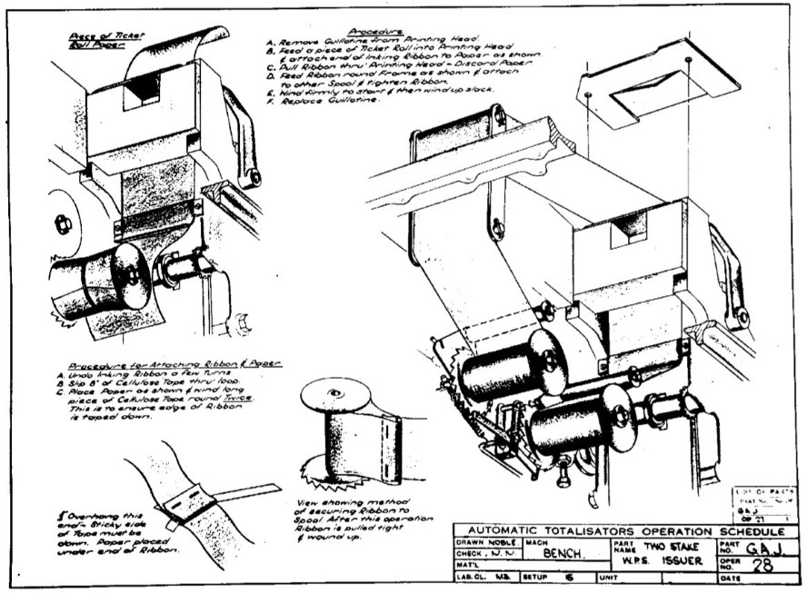
The text in the top left corner reads:
Piece of Ticket
Roll Paper.
The text below the left hand sketch of the printer in the image above reads:
The text in the bottom left corner reads:
Overhang this
end - Sticky side
of Tape must be
down. Paper placed
under end of Ribbon
Finally, the text bottom centre reads:
View showing method
of securing Ribbon to
Spool. After this operation
Ribbon is pulled tight
& wound up.
The boxlike part of the sketch in the top left corner of the image above is the Printing Platen Assembly. This Assembly can be seen being installed in the J8 in the image above titled J8 OPER NO. 7 Randall Park where it is labelled SAJ203. There is a square cut-out in the facing side of SAJ203 and this is where the race number barrel will be installed later in the assembly process, which has the race number type embossed on its perimeter. On the left hand side of SAJ203 an escapement wheel can be seen and this is the race number increment escapement wheel, that rotates the race number barrel one digit at a time, every time the race number is incremented on the Raceday Control Console or the Tote Control-room Switchboard, depending on the installation. Inside box number 2 shown in the image below titled J8 OPER NO. 31 Randall Park there is a sketch of the Race Change Rocker and its escapement wheel, a wheel which I have called the race number increment escapement wheel. Immediately below this Rocker, not seen in the sketch, are the Race Change Coils which activate the Rocker. The text in Box 2 reads Check Race Change Rocker & set the Clearance. The top plate seen on SAJ203, with the two screws protruding from it is the Guillotine. The two screws remain protruding and they both have springs on their shafts and turning the screws changes the pressure applied to the surface the guillotine is attached to by altering the tension of the springs. This guillotine can be seen in the top right corner of the image above, which is shown removed from the printer as suggested in item A of the Procedure list at the top of the image above and reproduced in the text immediately below that image. The two holes seen in the guillotine are where the shafts of the two screws fit through that have the springs on them. It is the pressure between the guillotine and the body of the printer that these screws adjust.
The rest of the printer assembly seen below the guillotine in the sketch on the right hand side of the image above, shows the ribbon path which loops from one ribbon spool to the other. These two ribbon spools operate together to perform the respective functions of Ribbon Supply Spool and Ribbon Take-up Spool, roles that are reversed when the end of the ribbon is reached on the current supply spool. There are two arms across the ribbon path seen in the sketch on the right hand side of the image above, one to the right of the two spools and one to the left, that are part of the ribbon spool assembly and look like ribbon guides, which also perform a sensing function. The left hand guide/sensor is shown with a broken outline as, from the perspective of the sketch, the guide is mostly behind the ribbon and is not visible. The guide/sensor belonging to the spool that is at the time acting as the ribbon supply spool, applies pressure to the ribbon introducing a kink into the ribbon path. When the supply spool comes to the end of the ribbon, it ceases to feed more ribbon out and the kink diminishes as the ribbon path starts to straighten out, this moves the guide/sensor arm out of the way, triggering a spring powered rotation of two triangular and interconnected pivoted plates that these arms are respectively attached to. This rotation, disengages the arm which was kinking the ribbon path and engages the other guide/sensor with its section of the ribbon, kinking that instead. I will call these triangular plates Ribbon Direction Change Plates. Another action resulting from the movement of the Ribbon Direction Change Plates follows: A ratchet wheel can be seen on the left hand side of both ribbon spools. A ratchet lever can be seen engaging a tooth on the left hand ratchet wheel. This lever spans between both ratchet wheels and is pivoted in the centre. The plate rotation also causes this lever to disengage from the left spool ratchet wheel and engage the right hand ratchet wheel instead, to accommodate ribbon motion in the opposite direction, and vice versa when the end of the ribbon is reached in that opposite direction ad infinitum. There is yet one more action relating to the rotation of these Ribbon Direction Change Plates. A wire that I will call a Ribbon Ratchet Reverse Lock is engaged across one of the teeth of the newly selected Ribbon Take-up Spool Ratchet and a similar wire is removed from the other spool, which will now be performing the function of the Ribbon Supply Spool. This wire allows the associated spool ratchet wheel to advance, the wire gently rising and riding over the sloped side of the ratchet tooth against the force of a spring, yet it does not allow the ratchet wheel to reverse, as in this direction the vertical edge of the tooth is blocked by the wire, which cannot rise over it. This ends the description of the ribbon direction change process.
Now we can see how the print ribbon is kept moving during the print cycle, a design to increase ribbon life and the duration between required ribbon re-inking. As can be seen in the sketch above, this ratchet lever pivot is mounted between two metal strips near the lower end of the strips. The strips are joined together at the bottom. At the upper end of the strips, there is another pivot on which the two metal strips themselves rotate. I will call this assembly consisting of the two metal strips and two pivots the Ratchet Lever Pivot Holder. A rod which I will call the Ribbon Advance Rod, which looks like an extension of the ratchet lever pivot, extends a short distance left from the left hand side of the Ratchet Lever Pivot Holder, where it turns ninety degrees heading towards the bottom right hand corner of the image above and after reaching a position near the right hand end of the ratchet lever it just stops. As this end of the rod in the sketch, does not show the two sides of the rod connected to each other, it signifies this is not the end of the rod, just that the rest of it is not pertinent to this drawing. This rod continues in the direction shown until it joins a lever which is driven from the other end, which is a cam follower, following the bottom end of the Print Press Cam. The complete Ribbon Advance Rod rod can be seen in the image above titled J8 OPER NO. 27 Randall Park, extending down the right hand side of the J8 from the top right hand corner of it. At the top right corner the rod is attached to the lever that is activated by the Print Press Cam which is hidden behind the paper chute in the image mentioned. At the bottom end of the rod as seen in the mentioned image, it connects with what looks like the top of the Ratchet Lever Pivot Holder, which actually is the bottom of it, as the mentioned image is a bottom view of the J8. Extending further down in the direction the rod is oriented, from the connection of the rod to the Ratchet Lever Pivot Holder is a strong spring, which is anchored at its other end in a tensioning screw connected to the frame. This is the spring that keeps the cam follower on the lever connected to this rod firmly in contact with the Print Press Cam. As the name implies, the Print Press Cam also activates the Print Press, however that is done by a cam follower on the upper part of this same cam. This means that the same cam, after it has actuated the Print Press to stamp the ticket paper, it activates the Ribbon Advance Rod to advance the ribbon take-up spool and hence the ribbon, to ensure that the press does not continually use the same part of the ribbon. Powered by this cam, the Ribbon Advance Rod causes the Ratchet Lever to push against the tooth it is engaged with on the left spool ratchet, seen in the image above, advancing it a tooth. The Ratchet Lever does not move around its own pivot, but moves as a result of the Ratchet Lever Pivot Holder moving around its own pivot near its upper end. The Ribbon Ratchet Reverse Lock wire holds the ratchet in place as the Ratchet Lever Pivot Holder returns to its centralised rest position with the tip of the Ratchet Lever riding over the tooth of the ratchet onto the next tooth. The ribbon can be seen doing a U turn around the ribbon guide rollers underneath the Procedure list top centre in the image above, and the section of ribbon running right to the body of the printer can also be seen in the image below bottom left where it rises around the upper ribbon guide, passes under the P.W.S bracket/arm and enters the printer's body below the ticket exit chute.
The ticket paper path through the printer is vertically up in this sketch above. At the bottom of the sketch the paper input chute can be seen disappearing off the bottom of the sketch. This ticket paper chute can also be seen in the top right corner of the bottom of the TIM shown in the image above titled J8 OPER NO. 27 Randall Park. Further down the right hand side of the J8 in that image the two ribbon spools can be seen. The paper then passes up through the body of the printer in the image above, through the guillotine and enters a short plastic chute, shown in the image below identified by an arrow and the name of the part SAJ96, where it exits the J8 from the slot on the top of this part. This slot can also be seen below the two right hand tickets on top of the J8, which came out of this slot in the image at the top of this page.
The square cut out in the top of the facing side of the body of the printer in the image above, as previously mentioned is to house the race number barrel. This facing side however is not the side of the printer where the printing takes place, rather it is on the opposite side. There is a press on the opposite side that pushes the platen onto the ticket type. This produces the type of tickets shown on top of the J8 in the image at the top of this page. The arm seen on the right hand side of the body of the printer in the image above is one of two, the other being on the opposite side of the body of the printer, that operate the guillotine. They are operated by the Guillotine Cam on the Printer Drive Shaft. The Guillotine Cam is used in the following emulation of a J8 machine cycle.
In box number 9 in the image below titled J8 OPER NO. 31 Randall Park, there is an alignment procedure and sketch associated with the Printer Guillotine Cam. It states With Guillotine Cam on peak position, set Trip Release Cam vertical. This Cam to have minimum end play. Note that above and below the Guillotine Cam hub in this sketch, peaking out above is a broken line outline of the bottom of the Trip Release Cam and similarly below the hub is the outline of the top of the Trip Release Cam, showing the Trip Release Cam in the correct correlation to the position of the Guillotine Cam. I have checked the J8 in my collection, which has not operated in 39 years and the Trip Release Cam is vertical a little early. The Trip Release Cam is also used in the following emulation of a J8 machine cycle.
As mentioned previously, the printer drive shaft is the main sequencer in the J8 and of course other electromechanical models of Julius Tote TIMs. It has eight cams mounted on it to perform the required sequence functions. I have discovered a way to manually emulate a machine cycle in the J8. This demonstrates the sequence of events implemented by the printer drive shaft so I have documented it here. First as a prerequisite to the Print Cycle, let's set the conditions for the Transaction Cycle which is the first part of two, constituting the machine cycle. The runner and pool are selected with the runner selection arm pointing to a runner and the runner selection arm knob pushed to the Win or Place position. If both are correctly selected the interlocks will allow the runner selection handle to be depressed. When depressed, the Handle Locking Latch will engage through the action of a spring. The TIM now has a bet pending and is waiting for the distributor/scanner to scan it. As it is not attached to a working Julius Tote and the Tim has no power source, we have to emulate this. Normally the betting circuit current builds up tripping the associated escapement wheel in the Horse Adder and the Grand Total Adder and finally the Trip Switch in the TIM. To emulate the tripping of the Trip Switch I push the Trip Switch Rocker towards the Trip Switch Coils, which would normally be done by the magnetic field, and the Trip Switch Rocker is latched by the Blade powered by a spring. This activates the Trip Switch, which breaks the Transaction Circuit and activates the magnetic clutch circuit, causing the continuously running drive motor to drive the Printer Drive Shaft. As the TIM has no power, the clutch does not engage and the motor is not running anyway. We are now however in the emulation of the Print Cycle and as the clutch is disengaged it is easy to hand crank the Printer Drive Shaft drive cog.
Rotating this cog in a direction that turns the drive shaft anticlockwise when viewed from the left hand end, the first things that happen is that the Guillotine Cam, which is at the left hand end of the drive shaft as described, starts raising the guillotine, which disengages it. Simultaneously, the next cam on the shaft, the Print Press Cam pushes the Platen onto the ribbon and the type to be printed on the ticket. Next this cam starts to raise the Platen again. Whilst the print platen continues to be raised, the two Paper Advance Cams push the ticket paper onto the two rubber rimmed independently driven Paper Advance Rollers advancing the ticket paper up the paper entry chute. One of the Paper Advance Rollers can be seen in the sketch above mounted on a shaft across the paper entry chute, seen extending to the right from behind the top of the right hand ribbon spool.The roller visible can be seen contacting the paper through a slot in the paper chute. When the ticket is about half way out of the machine, which is not happening as there is no paper in the machine, continuing to manually crank the drive gear, the Handle Lock Release Cam comes in contact with a flange on the handle locking lever, pushing it away from the Handle Lock Switch activating arm, allowing it to release the switch and the handle to pop back up, powered by a spring. Just prior to reaching 135 degrees of drive shaft rotation since the Handle Lock was released, the Paper Advance Cam ceases to feed the ticket paper up the paper chute and the Guillotine Cam reaches a point where the radius declines rapidly, where it will apply the guillotine when the cam follower rides down the slope of the cam's declining radius, to cut the ticket off from the continuous paper supply. Shortly after that the Trip Switch Cam comes in contact with a flange on the Trip Switch Blade, disengaging it from the Trip Switch Rocker allowing the Trip Switch to reset powered by a spring. The deactivating of the Trip Switch removes power from the magnetic clutch ceasing the rotation of the Printer Drive Shaft, as the Printer Press Cam Follower stops in a dip in the Print Press Cam, which is the rest position for the shaft. So ends the emulated machine cycle.
My emulation has utilised six of the eight cams on the Printer Drive Shaft. One of the cams not referred to is the Cam Operated Switch Cam which operates the two Veeder Root Counters already described. The other cam that is not mentioned in my emulation is the Safety Cam, which operates one half of the Handle Lock Switch which has been previously described.
Following is an extract relating to the J8 printers from a talk Neville Mitchell gave on the Julius Totalisators, which is presented in the The Premier Tote Operation 1930 + Neville's talk of this website:
Under ideal conditions and with a properly maintained and nicely tuned mainframe adder, the J8 could produce 90 tickets per minute which was the mean average they could do and this dependent on a fair few things as well as the skill of the operator. I noticed in Melbourne in the 1960s and later that competition between the ticket sellers especially in the smaller totes like in the Owners and Trainers and Bookmakers Tote area and places like that.
Before leaving the subject of the J8 printer, I will mention that the J8 had an extendible paper holder inside the bottom rear of the case. This was permanently attached to the base of the case and could be pulled out of the case through a square hole and slit in the bottom of the case. In its retracted and extended positions the extension arm would have resistance to movement which had to be overcome to get it moving, so that it would remain in the position it was last left in. The paper roll would be placed on the horizontal arm of the holder which kept it in a convenient proximity to the paper entry chute on the J8.
The image below has instructions in the bottom left corner and the final line contains an item of importance. It reads:
SELECT SUITABLE HORSESwarf disposal was very important, not only in the machinery but on the factory floor and tables as well. Following is an extract from the Memories of the final factory chapter of this website that relates to what Neville Mitchell has to say about Swarf and the Meadowbank factory:
NUMBER AND PLUG IN.
DRILL HOLE THROUGH TYPE
WHEEL CASTING (PILOT
HOLE IS IN GEAR) USE #3;
DRILL.
TAPER REAM TO SUIT TAPER PIN.
DRIVE IN PIN FIRMLY & ENSURE
HEAD CLEARS W.P.S. ARM
SCREW TICKET CHUTE TO PLATEN
ASSEMBLY.
REMOVE ALL SWARF. THIS IS MOST IMPORTANT.
The organisation was impressive and there was a lot of very impressive people involved in the place. The first thing that struck you was the cleanliness, the building was sparkling. You could walk around the machine shop in bare feet and you wouldn't tread in machine swarf nor would you get grease or oil on you. The organisation of the place stemmed from most of the people having served in the forces during world war 2, so they brought with them the disciplines of the Navy, the Air Force and the Army. Most of the guys leading the place such as foremen, production managers and the like which I had contact with initially, were very very strict. You had to be in the right place at the right time and you had to have the right piece of paper accompanying the work that you were doing. Everything was run by bells and whistles, there was a clock on system and a bell that went to start work and a bell that said it was morning tea and a bell that said it was lunch and a bell that said it was afternoon tea and the one in the afternoon which was the knock off bell which resulted in pandemonium. At peak times when we would have something like between 250 to 280 women working in the wiring department alone, who all wanted to get home, it was a stampede for the doors and the bundy clocks to clock off.The note on the right hand side of the image below clarifies the drill mentioned in line five of the list above and specifies the Taper Reamer to use and reads:
USE No 3; DRILL &The W.P.S. ARM mentioned in line nine of the list above the two line list, is what is called the Win Place Show Arm. This seems to be marked P.W.S. on the metal object that looks like a bracket to the left of the centre of the Horse Halo in the image below. This could be the arm mentioned. Below this bracket/arm there is a strip that looks like ticket paper that runs from a guide at the near side of the TIM to the printer above the P.W.S. bracket/arm. Above the rear side of the TIM there is a drawing identifier SAJ96 which points to the ticket exit chute on top of the printer. The strip that I likened to ticket paper, is not ticket paper but an ink ribbon for the printer. The ticket paper is fed from below.
No 000 TAPER REAMER.
In the Sequence of Operations & Parts Fitted list above, Operation Number 33 is listed as 33 Taper Pinning Operation and 33A, which is the drawing below, is listed as 33A Ticket Issuer Chute. It can be seen in the text from this drawing above that the Ticket Issuer Chute or TICKET CHUTE in line 10 is being screwed to the PLATEN which is already on the TIM in this step.
The image below shows the final touches being applied to the TIM as shown in the the bottom left hand corner of the drawing and in the transcription text below. In the Sequence of Operations & Parts Fitted list above, Operation Number 34 is listed as 34 Covers & Horse Number Segments. The covers are mentioned in the text below and the NUMBER STRIPS mentioned in line 13 being stuck on, are the Horse Number Segments mentioned in the Sequence of Operations & Parts Fitted list.
CHECK HEIGHT FROM TOP OF
COVERS TO RUNNERS.
SET WITH TWO SCREWS IN BOX
TO CORRECT HEIGHT.
CHECK COVERS FOR FLATNESS.
CHECK FRONT OF BOX & COVER
FOR .010' PROTRUSION.
CHECK HANDLE CASTING FOR FOULING.
CHECK COVER JOIN DOWN CENTRE
OF BOX.
ENSURE COVERS ARE EASY TO
REMOVE & REPLACE.
STICK NUMBER STRIPS DOWN WITH CEMENT
AFTER DRILLING.
SPOT THROUGH STRIP INTO COVERS AFTER
CHECKING SELECTION.
RIVET STRIPS TO COVERS.
FINALLY TEST ALL NUMBER SELECTION.
The following First Test Check List below is mentioned in the Sequence of Operations & Parts Fitted page shown above, which is part of the General Assembly of Ticket Issueing Machine document. Item 32 of the Sequence of Operations & Parts Fitted page, calls upon this test to be performed with the words First Test. The page containing the checklist items below has Operation 32 in the bottom right corner with George Julius' initials GAJ above. This identifies this "First Test" shown below as Operation 32.
I note that in the original document the list appears without any "I" entry and the list jumps from H to J. I have presented the list below the same way so it is true to the original.
First Test
note especially all adjustment Locknuts for tightness.
Type Wheel, Win, Place & Show. Check settings of these
adjust if necessary
in Horse Quadrant
'Test.' 'Central' & 'No. 1'
The following Final Test Check List below is also mentioned in the Sequence of Operations & Parts Fitted page shown above in Item 35 the entry for which is Final Test. Similar to the First Test page, the page containing the checklist items below has Operation 35 in the bottom right corner with George's initials GAJ above. Item 35 in the Sequence of Operations & Parts Fitted list above is Spray Finish Issuer Box and the detials for this are shown below.
Final Test
all Horses and Test.
set of Tickets.
Cellulose Tool Place Tickets in bottom of Issuer
between the Former and the Case.
Pinning Operations Particularly inspect
Ink Ribbon on this point.
Bench Top.
The following Spray Polish issuer Box Check List below is also mentioned in the Sequence of Operations & Parts Fitted page shown above in Item 36 the entry for which is Final Test. Similar to the First Test page, the page containing the checklist items below has Operation 36 in the bottom right corner with George's initials GAJ above.
Spray Polish issuer Box
Masking Tape
On the subject of Polish, the finish of the machine was very important. The following is an extract from part of an email presented at the bottom of this page, sent from Rod Richards who worked for Automatic Totalisators Limited, during the period of J8 production:
One thing that intrigued me with the issuer assembly was the preparation of the two issuer covers. These were made of stainless steel in the sheet metal section of the factory. Great care was used to promote the appearance of these covers with two men dedicated to polishing the covers with oiled Emery cloth on a block, rubbing back and forth to produce a fine finish along the length of the covers.The two issuer covers Rod mentions can easily be seen in the image at the top of this page with the horizontal join of the two covers spanning the width of the J8 half way between the edges and passing underneath the runner number arc and the runner selection arm.
Finally a copy of the Operation Number 31 drawing which in the Sequence of Operations & Parts Fitted is called 31 Electrical Setting Details. This is where all the tuning is done or what in the electronics era would be called an alignment procedure. Item one is worthy of a special note:
It reads Check wiring of issuer to Wiring Diagrams W275 & W276. Use a 'Bell Set' & ring each wire through. In my time, I would have used a multimeter, or in my early period an AVO meter to measure the resistance of connections. AVO stands for Amps, Voltage, Ohms, the three electrical measurements the meter can perform. Prior to my time, although I have seen them used, a simpler device was used to prove connectivity called a Bell Set. This basically was a power source and a bell with leads attached to them, which when shorted out rings the bell. In this way it is possible to determine that two points in a circuit, that are supposed to be connected together by a wire or other conductor, are actually connected, by placing a lead of the Bell Set to each of the two test points of the circuit being tested, then if the bell rings the wire is present and this is what item one in the image below refers to as ring each wire through. "Each wire" refers to all the wires in the Wiring Diagrams mentioned and the information in the General Assembly of Randall Park issuer Wiring Information table above, and above that the J8 Circuit Diagram Randall Park, can also be used for that purpose. The bell often was a tone generator, the point being something that makes a noise if the contact points the leads are connected to, are electrically connected to each other. This way wire connections between contact points can be established by a threshold level of noise. It is 2018 and I note that there are still modern versions of this device available. These are good for a single person to find wire pairs somewhere removed from the location of the Bell Set, which is attached to the pair of wires wishing to be located at the other end so long as the bell set can be heard from the other end. Then it is only a matter of shorting out pairs of wires at the other end until the Bell Set is heard, confirming that the pair has been found.
Another interesting aspect of this old machinery, is that gaps are often measured by the diameter of a drill instead of using a feeler gauge. I can remember using feeler gauges, primarily to set the ignition points gap in the distributor, when car and motorcycle engines had these mechanical devices. The other item I have often used a feeler gauge for is setting the spark gap in the spark plugs of reciprocating engines, a need that outlived that of the points in the distributor. If you have a readily available drill of the right diameter however, I can see no reason why not to use that as a gauge for setting a gap. Having mentioned distributors in engines, the car distributors share their name with the Time Division Multiplexers in the Julius Tote which were initially called Distributors and later seemed to be called Scanners. I can see the similarity between an ignition distributor in a car and the Julius Tote Time Division Multiplexers (TDMs). The former triggers a spark in a sequence to multiple spark plugs and the latter creates an enabling pulse for a group of TIMs in sequence, a process reminiscent of the later protocol concept of polling. As an example of a drill being used to set a gap, item four in the drawing below has the following text associated with it: Check Trip Coil Rocker & Set clearance using a No. 50 Drill on top, with the following text on the left hand side: .07 Drill must pass thru. The enlarged view circle inside the number four box, shows the end view of the drill as a small filled black circle between the rocker arm and the top of the coil. The upside down screw inside a threaded holder, shown in the number four box, with its tip in contact with the rocker arm on the right hand side of the rocker arm fulcrum, is the means of adjusting this gap.
As previously described, the Trip Coil is a critical part of the Betting Circuit and terminates the transaction cycle. This trip coil is the one that is arranged so that it is slower in operation than those in the escapement magnets in the Horse Adder and the Grand Total Adder, to ensure that the trip switch is not opened before the bet is recorded which would prematurely terminate the transaction cycle, as previously described in this page in the extract from the company document titled Automatic Totalisators Limited Description of Electrical Circuit Diagrams under the heading titled BETTING CIRCUIT./ Drawing No. 3509. This timing is adjusted in item five in the drawing below which has the following text: Set Trip Coil Rocker Spring Tension To Trip Rocker at 1.2 to 1.3 Amps.
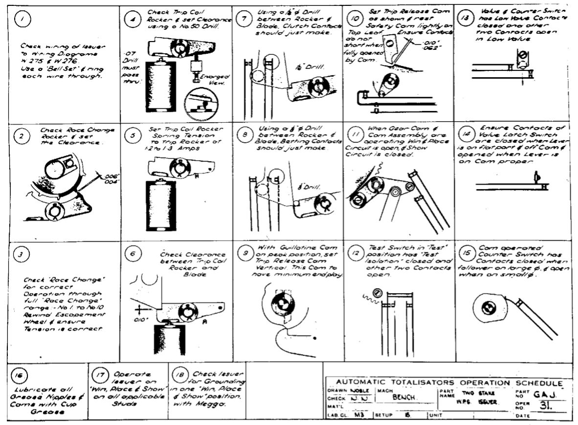
Finally, on the subject of the Trip Coil, following is another extract from the company document titled Automatic Totalisators Limited Description of Electrical Circuit Diagrams:
In the old type of Issuer there is no trip coil and trip switch which starts the issuer after the bet has been registered. The issuer starts to issue the ticket immediately the handle is depressed and a switch is then closed which completes the betting when the distributor reaches the corresponding contact stud and the bet is registered. In series with the escapement magnets there is a magnet on the issuer which trips an arm and permits the ticket to be ejected out of the machine. If the betting circuit is not completed before the issuer completes its cycle, the magnet on the issuer does not trip the arm and the ticket is delivered into a locked box on the issuer.
With this arrangement the distributors must run faster than the Issuers so as to ensure that the bet will be registered and the ticket release arm tripped before the issuer completes its cycle.
This is the only difference in the Betting Circuit with the old type of issuers as compared with the latest type as indicated on Drawing No. 3509.
Webmaster's notes:
The above entry relating to the OLD TYPE OF ISSUERS reveals something important about the Julius Totes. They did not issue tickets for transactions that had not been recorded due to some fault condition. The first sentence in the second paragraph below the title above In the old type of Issuer there is no trip coil and trip switch which starts the issuer after the bet has been registered, tells us that in the latest Julius Tote TIMs the TIM, or what is referred to as issuer, is not started unless the bet has been registered. This means the TIM does not perform a Print Cycle to print a ticket unless the bet has been recorded. The way this is achieved is that the trip coil mentioned is in series with the Betting Circuit, so that the current that is flowing through the associated Adder's escapement magnets, also opens the Trip Switch in the TIM/issuer which starts the print cycle. In other words, the current that is recording the transaction in the Adder also triggers a print cycle in the TIM. Conversely if no current flows through the Adder's escapement magnet, due to any open circuit fault in the Betting Circuit, then no print cycle takes place.The second sentence in the second paragraph below the title above also informs us that in the OLD TYPE OF ISSUERS, The issuer starts to issue the ticket immediately the handle is depressed. At the end of the second paragraph below the title above we are also informed that if an unregistered ticket in the OLD TYPE OF ISSUERS is printed the ticket is delivered into a locked box on the issuer. This keeps the ticket out of circulation to keep it from being used fraudulently and will later be destroyed.
![]()
What I find amazing about all this is what I call Engineering Artwork. All the drawings above are 1950 engineering drawings. This sort of engineering documentation heavily oriented around drawings, go back to the origins of Automatic Totalisators Limited in 1917. I can remember enjoying an Engineering subject called Technical Drawing. I can remember at the time thinking it was quite artistic, although it did not involve anything more than the good old tools one had at school in the Geometry Sets, which were usually supplied in a metal tin. These generally included a ruler, set square, compass and a pair of dividers. There was nothing in this subject that required freehand drawing however. I am astounded at what drawings were made like the ones above in Engineering Companies prior to the advent of CAD/CAM systems. I wonder how long it would have taken to produce some of these drawings. George Julius' engineering consulting company Julius Poole & Gibson, published a book called Julius Poole & Gibson The First Eighty Years. This book had a subtitle From Tote To CAD. This subtitle seems particularly pertinent when thinking about the drawings produced. I remember the Drawing Offices producing these drawings that used to be sizeable departments, which used to be a hive of activity. I believe Art definitely exists in Engineering and that this is particularly the case with Engineering Drawing/ Technical Drawing. As previously mentioned, the personal computer and the readily available CAD/CAM software put an end to the need for Drawing Offices.
On the subject of Engineering Drawings, it reminds me of an Anecdote from Jim Loveday, who was a Partner of Julius Poole & Gibson, which is extracted from the book Julius Poole & Gibson The First Eighty Years:
Jim Loveday had a cheery and affable personality. He loved to tell a story of the early days when he was working under the usually strict and demanding eye of George Julius. The following anecdote took place at Culwulla Chambers.Sir George had a buzzer installed which he used to summon us to show the progress of our work. One day the drawing I had just finished blew out of the window and floated down Castlereagh Street where it was run over by a tram. I rushed down stairs, retrieved the remains of the drawing and got back just in time to hear the buzzer sound twice which was the signal for me to present my work.
Sir George slowly eyed the mutilated drawing in my hands and simply remarked dead pan "You've made quite a mess of this drawing, Loveday, I expect to see some improvement in future".
After all this latest investigation, resulting from incorporating Bob Doran's Riccarton Automatic Totalisators Limited documents and Garry Elliot's J8 assembly company document into this and other pertinent pages of this website in September/October 2018, I now find myself in the peculiar situation of feeling confident I could get a job anywhere in the world as a Julius Tote Engineer. As Maxwell Smart from the TV show Get Smart would have said, it was a great plan with one minor flaw! I am retired and thoroughly enjoying it and I am at least half a century too late!
![]()
Following are some extracts of emails from ex Automatic Totalisators Limited staff in January 2019, after they read this page of the Totalisator History website, with its latest additions. The first is an extract of an email from Bill Johnson. Bill was a long serving Engineer and Manager with Automatic Totalisators Limited, spending much of his time with the company working overseas. Interestingly, Bill's father, another William Johnson also was a long serving engineer and manager with Automatic Totalisators Limited who spent much of his time working overseas:
Bill's mention of shovelling snow led me to wonder where Randall Park was located. North Randall seems to be a suburb of Cleveland Ohio and Randall Park was close to Jack Thistledown Racino. I am quite accustomed to finding that many of the tracks where Julius Totes operated no longer exist. Therefore, it was no surprise to find that Randall Park Shopping Mall had been built on top of it, a fate shared with the Harringay Dog track in London. What did surprise me regarding Randall Park, is that time has also dispensed with the Randall Park Mall era and that it had become the object of those who examine abandoned places in America. Randall Park Mall closed in 2009 with demolition starting in 2014. Having mentioned Jack Thistledown Racino, it is interesting to note that an American subsidiary company of Automatic Totalisators Limited installed a computer totalisator at Thistledown Race Track Ohio.Wow!!! Great article. Brings back a lot of memories. From electrical inspection one of my jobs was to fix electrical faults on J8 issuers on the production line. Learnt a lot of mechanical work from Pat Britain? As apprentices we rarely saw any of the mentioned drawings and instructions, 1954 to 1956 for me. Most instruction came from working with different tradesmen weeks or months at a time.
My father was in charge under Spencer Grace at this time at Randall Park. I remember Don Raison, Fred James, Alan Lakeman, plus others I have forgotten. (We arrived months after my father in Las Vegas in February, 1951. I think the first Atom bomb had been dropped 80 miles away, exploding at 300 feet, dropped from a bomber two weeks previously). Dad had been in the USA for six months earlier then returned late 1950. At times they had to shovel snow away from the door to enter while working on the indicator.
Neville Mitchell added the following comment on reading this page:
One slack time in the Drawing office my boss Alf Lesions was aghast when I suggested that I write a description and service manual for the J10 . Some 55 pages and drawing later I presented it to Alf.I hope that this page has more readers than Neville's J10 description and service manual!I do not think he actually read it and it eventually got "Lost" in a clean up of the document store.
Following is an extract of an email from Peter Collier who was a long serving Engineer and Manager with Automatic Totalisators Limited. He was in charge of engineering in the Melbourne Branch of the company and I was his counterpart in Brisbane. Peter was a highly accomplished computer engineer with the company by the time I started. Like Bill Johnson, Peter's father also worked for Automatic Totalisators Limited.
I enjoyed the J8 information, it was the first TIM I ever worked on, along with the original J10. We did carry these by ourselves, I often think about how often we did this and thought nothing of it, I know I couldn't do that now. We were a lot fitter in those days ( and younger ).Peter suggested that I check with Neville Mitchell to see if he remembers S. Huss, the Riley and his visiting Melbourne in 1965. An extract from Neville's reply reads:The General Assembly document that was issued to S Huss was interesting. I think that I met him in Melbourne in 1965. Everyone called him Snowy Huss and he drove an old Riley which he was quite obsessed with.
Yes that is correct Snow Huss did have a Riley and a Jaguar, he mostly drove the green Riley he kept the Jaguar for impressing his dates, it was a yellow sports model. Also at about that time Don Hardy had a Singer 10 sports car.MMRC stands for Melbourne Metropolitan Racing Clubs.I seem to remember Huss did visit MMRC for a day or so.
A comment made about the Randall Park project before the existence of this page was made by an ex Automatic Totalisators Limited engineer Rod Richards, who worked on this project. He made the following comment about the project relating to his working on it in the Meadowbank factory:
This must have been 1950 as we worked on the Randall Park job in the factory as a matter of urgency, during the Xmas/New year period, to have the machine finished in time for the Randall Park Carnival racing period. From memory we worked a lot of overtime to get the job finished and I believe air freight was involved. I think Alan Lakeman and Jim Macintyre were just two of the Meadowbank engineers that worked on the installation at Randall Park.On reading this page Rod Richards added the following which is an extract of an email he sent in January 2019.
Following is Neville's comments about Rod's email. A major improvement on polishing the J8 top covers two decades later and an observation that the lot of apprentices significantly improved from 1949 to 1962. Autotote that Neville mentions was the Automatic Totalisators Limited subsidiary company in the United States.I certainly remember Snowy Huss, both when I worked at ATL in 1949 and again when I re-joined ATL in 1960.
In 1949 modes of transport were very much the topic of the day as most of us apprentices at ATL had a push bike and rode to work, the factory even provided a special covered bike rack at the back of the factory in front of the fitters maintenance shop. A few lucky ones had a motor bike, which created a lot wishful thinking. Very few people at ATL had cars, as at that time, new cars had a long waiting list to purchase and second hand cars were expensive and also hard to come by.
Snowy Huss had a post war RM Riley, which must have been relatively new at the time (1949) as RM Rileys only started to be produced and exported in late 1946. I think Snow's car was a RMA 1½ litre as these were the first made and were the most plentiful; the RMB 2½ litre followed later in late 1946 or 1947. Both the RMA and RMB were 4 door sedans and very popular - My Roadster is a RMC 2½ litre and was built in early 1949 arriving in Australia in April of that year and is one of the 507 Roadsters manufactured, mainly for the American market - which did not work out and Australia got a fair share of the US market cars. Today Roadsters are few in number and sort after. Bruce and I are planning to go to the Riley National Rally in May - this year it is at McLaren Vale in SA.
It is interesting that Peter Collier mentions that in 1965 Snowy was still driving an old Riley, maybe the same car that I knew he had.
You have a great deal of information on the J8 Issuer (TIM). My experience with the J8 does not go to anywhere near that you have put in the Totalisator History. In the factory in those days, with the Randall Park job and others, I was confined to the Adders. The Issuers were a separate assembly section and I never had the opportunity to work in that section. One thing that intrigued me with the issuer assembly was the preparation of the two issuer covers. These were made of stainless steel in the sheet metal section of the factory. Great care was used to promote the appearance of these covers with two men dedicated to polishing the covers with oiled Emery cloth on a block, rubbing back and forth to produce a fine finish along the length of the covers.
Once in the field, all that changed with the general maintenance and running of the totalisator taking place. The J8 from my experience was a very solid machine requiring little attention apart from the occasional paper jam on race day and other scheduled jobs, like inking ribbons - an irksome messy job. When I was based in Adelaide (1952-55) race meetings were held mainly at Victoria Park racecourse on the outskirts of the city, with a number of meetings held at Morphettville racecourse. Both these racecourses shared the J8 Issuers which were boxed and transported to each racecourse between meetings. Our job was to pack and unpack the issuers in the metal carry boxes, install them and run tests - I can believe that they weighed 85lbs, as Joe Brandon mentions in his article on the J8.
Rod mentions the two parts of the J8 top covers and their finishing. David McFarland the then circa 1970 production manager, arranged the purchase and installation of a large belt type sander to finish the J8, J10 J11 J18 top covers. The cover was loaded onto a rack that traversed the rolling sanding belt, an operator moved the cover under the belt thus obtaining a linear brushed finish. The machine was 4 metres long and was sited in the Transport area.
There was a fair number of employee cars in 1962 the car park was extended over time to take the expanding car ownership. The Company cars were FE Holdens 3 speed gear box column shift and there was not too many of them. Ron Hood was astounded when he went to Autotote in 1968 to find the apprentices all drove Mustangs and earned $5 an hour. The Mustang base price was $2200. Strangely the apprentices at Meadowbank all drove good cars one even bought an MD's car it was some type of 1950s Chevrolet? They all earned good money with overtime in the factory then compulsory attendance at the Sydney races trots & greyhounds, where they got wages travel and meal money.
| Acknowledgements |
Comments and suggestions welcome to totehis@hotmail.com 
The following page accessible via the Next page button below, contains relevant extracts from the company document titled Automatic Totalisators Limited Description of Electrical Circuit Diagrams dated 15/5/1935 related to the Julius Tote Adders, or Adding Units as referred to in the 1935 document.
The previous page, accessible via the Previous page button below, contains the complete text from the company document titled Automatic Totalisators Limited Description of Electrical Circuit Diagrams dated 15/5/1935, as well as two blueprint drawings relating to the second Julius Totalisator that was installed at Riccarton Racecourse in 1935. The first Julius Totalisator was installed at Riccarton in 1921.
| Previous page | Go to the index | Top of the page | Next page |