This technology history page, significant in the history of computing that contains a photograph, which is one of several belonging to the photo gallery pages, which are part of several pages relating to the invention of the world's first automatic totalizator in 1913 and Automatic Totalisators Limited, the Australian company founded by George Julius in 1917, to develop manufacture and export these systems.
Copyright © 2018 Email - totehis@hotmail.com
Historic Technical Drawing Blueprint
In 2007, I visited Riccarton Racecourse whilst in Christchurch and was very surprised to find a Julius Tote Barometer Indicator in excellent condition on the side of a building on the racecourse. I was further amazed to find that the Julius Tote mainframe that drove this indicator was still present in the building. I informed Professor Bob Doran from Auckland University of this and he organised a visit to see this system and identify what was still present and examine research and document it. As a result of this, Bob sent me many photographs of the equipment and some of the documents he found there. I never cease to be amazed how Bob, so entrenched in the future, having been Principal Computer Architect at Amdahl Corporation, designing tomorrow's computer systems and later a Professor working on educating the next generation of computer engineers, could be so passionate about the past and the path taken to arrive at the present state of computer technology. One of the documents he sent me is titled Automatic Totalisators Limited Description of Electrical Circuit Diagrams. In this there is a page titled LIST OF CIRCUIT DIAGRAMS DATED 15/5/1935. There are several circuits described in this document and I have included all the text from it in this page. Two Julius Totalisator installations were performed in Riccarton, the first in 1921 and the second in 1935 to which the company document describing the Electrical Circuit Diagrams belongs. The two Automatic Totalisators Limited Blueprint Drawings presented in this page, starting with the one immediately below, also belong to Prof Bob Doran's collection, relating to the 1935 Riccarton Julius Totalisator.
Click on the image to go back to the Photo Gallery
If you arrived from navigating the website, use the navigation bar at the bottom of this page.
The Blueprint Drawing above was produced by Julius Poole & Gibson, George Julius' engineering consulting company.
I find the blueprint drawing above and the one further down this page of particular interest for two reasons. Firstly the fact that they are blueprints. I recall there being a proliferation of blueprints in the AWA Print Room located at the North Ryde factory in Sydney in the early 1970s. This was a once common means of reproducing engineering drawings. Despite Blueprints becoming so common that the word became part of the English language, they now seem to have disappeared into antiquity as I have not seen any blueprints in decades. Secondly, the drawing below titled Julius Poole and Gibson blueprint, as well as the one above, were produced by Awdry Julius, George Julius' son, who was working for his father's other company Julius Poole and Gibson. I determined this from the drawing identification box in the bottom left corner of the drawing below as well as the identification box of the original image of the drawing shown above. I have not presented the whole original image above, because of the damage to the drawing and I have performed repair of the original image in what is presented above. This identification box in the Julius Poole and Gibson blueprint drawing below also has a creation date, which like a lot of the writing in this image of the blueprint drawing is blurred, however I am quite confident it reads 29 4 34 which is 29th April 1934.
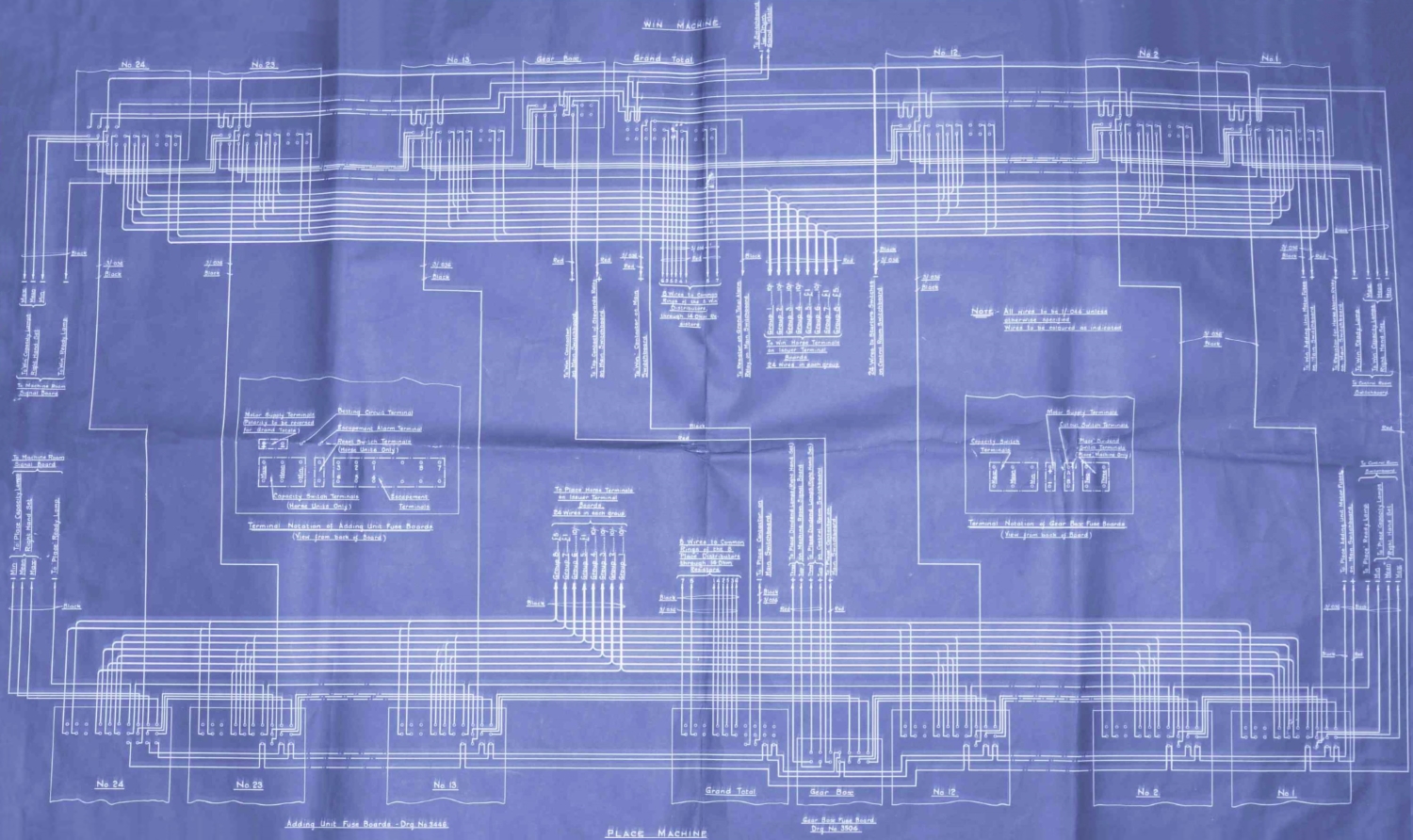
The image above is one of a collection of photographs of Julius Tote Blueprints that Bob sent me. It is a simplified interconnect diagram of a Julius Totalisator and the original drawing is titled WIRING TO ADDING UNIT FUSE BOARDS, not shown in the image above and bears the drawing designation that looks like 3500 - 713 however the lower part of 713 is obscured. Top centre of the image above are the words WIN MACHINE and bottom centre PLACE MACHINE. The drawing makes reference to two other drawings, the Adding Unit Fuse Boards Drg. No. 3446 bottom left and the Gear Box Fuse Board Drg. No. 3504 bottom to the right of the words PLACE MACHINE. I have not included these drawings in this page, however the Adding Unit Fuse Board is very similar to the Grand Total Fuse Board on the left hand side of the blueprint drawing several images below, titled Julius Poole and Gibson blueprint , and the Gear Box Fuse Board drawing is the same as the one shown in the bottom right quadrant of the same blueprint drawing below.
Every box in the drawing above, has a squiggly line either on the top or the bottom. I take this to be indicative of the fact that these boxes are not complete and are only representative of the equipment contained in them, which would be available if the part beyond the squiggly line was visible. Additionally every box in the drawing above contains a drawing representing an electrical connector or connectors. In all boxes except the ones labelled Gear Box the connectors are the same. They consist of two parallel rows of ten contacts or connection points each, with a third parallel row of four contacts, all of which look like little circles. I will refer to these contacts as pads, as this is what they are called on PCBs (Printed Circuit Boards.) Having mentioned PCBs, I must point out that the early Julius Totes pre-dated PCBs. These connectors are not the traditional connectors we think of in the electronics industry today. They are not self contained units arranged as plugs and sockets. They have connection points which I have called pads, which I suspect are solder joints. I will have a close look the next time I am near an old Julius Mainframe. In mainframe pictures of this Julius Tote era, these connection points are visible, without any detail, arranged exactly as seen in the drawing above, with two parallel rows of ten contacts and a third short parallel row of four contacts. The old text refers to these contacts/connection points as terminals. This can be confusing in the computer era as the TIMs (Ticket Issuing Machines), or in this old text what are called Issuers, can be thought of as terminals. The extra row of four contacts is flush with one end of the other two rows of contacts. It is interesting to note that the boxes seen in the row across the top of the drawing above, have been rotated around 180 degrees in the row across the bottom of the drawing. This is why the short row of four contacts move from being at the top left end of the connector in the top row boxes to the bottom right end of the connector in the bottom row boxes. This arrangement of connector is also seen in the blueprint drawing below titled Julius Poole and Gibson blueprint at the bottom of the box titled Grand Total Fuse Board on the left hand side of the drawing.
There are two boxes, which I call detail boxes, in the drawing above that are larger than any of the other boxes, one in the middle of the left hand half of the drawing and the other in the middle of the right hand half of the drawing. The left hand box has a label below it with Terminal Notation of Adding Unit Fuse Boards in the top line and View from back of Board below. The contents of this box shows the signal names for the conductors attached to all the connectors inside the Adding Unit Fuse Boards which are the ones titled No 1, No 2, No 12, No 13, No 23 and No 24. Although I have named these boxes detail boxes because they provide details about the use of each pertinent contact pad, it is obvious they do not provide any details of the component parts of the box which requires reference to additional detail drawings as seen in the blueprint drawing below.
A horizontal pair of contacts/pads in this Terminal Notation of Adding Unit Fuse Boards detail box, can be seen top left in the detail box, with a squat rectangle around them. This rectangle is labelled Motor Supply Terminals with the line (Polarity to be reversed below that, with for Grand Totals) in the third row. All three lines are underlined with the lowest underline extending to an arrow pointing back to the rectangle. Below the left pad is a + sign and below the right hand pad is a - sign. This is the direct current supply for the Adder's motor. To the right of the rectangle, is a single pad with a bent arrow pointing to it, which has the text Betting Circuit Terminal on the horizontal part of the arrow. The Betting Circuit is a rather complex circuit used to record tote transactions on the appropriate Adders. More on this later. To the right of that again, is another single pad with a bent arrow pointing to it, which has the text Escapement Alarm Terminal on the horizontal part of the arrow. The escapement alarm, signals the failure of the drive to an adding shaft in a particular adder. Below this Escapement Alarm Terminal line of text, there are another two separate lines, which read Reset Switch Terminals on top with the text (Horse Units Only) below, with an arrow on the left side of the text pointing down to the middle of three differently shaped rectangles. This middle rectangle is the thinnest of the three, containing two pads one on top of the other. The Reset Switches are a part of a signalling method described under the heading below 'RESET', 'READY' and 'ON' SIGNAL LAMP CIRCUITS./ Drawing NO. 3488. To the left of this middle rectangle is a wider rectangle containing three pairs of vertically separated pads arranged side by side, with an arrow pointing to it from below, with associated text reading Capacity Switch Terminals with a line below that reading (Horse Units Only). The three pairs of vertically separated pads have words between each pair of pads, that are rotated anticlockwise 90 degrees, so they sit vertical between the pairs of pads, that read Max between the first pair and Mean between the second pair and Min between the final pair in this rectangle. Max Mean and Min are capacity configurations for the expected turnover of a race used by the odds calculating system. Finally, to the right of the middle rectangle of three at the bottom of the Terminal Notation of Adding Unit Fuse Boards box, is the widest rectangle, containing six pairs of vertically separated pads sitting side by side, with an arrow pointing to the rectangle from below, with associated text reading Escapement above the word Terminals. The first three pairs of pads on the left hand side of this rectangle have numbers between each pair of pads with 3 below the first top pad, 2 below the second top pad 1 below the third top pad and similarly 6, 5, 4 above the first, second and third bottom pads respectively. Of the remaining three pairs of pads on the right hand side of this rectangle labelled Escapement Terminals, only two have associated numbers. They are the top right hand two labelled 8 on the left and 7 on the right. These pads are the means of connecting the electrical bus lines consisting of eight conductors, spanning most of the width along the top and the bottom of the blueprint drawing above.
The second of the two detail boxes previously mentioned, which is in the middle of the right hand half of the drawing above, has a label below it with Terminal Notation of Gear Box Fuse Boards in the top line and View from back of Board below. The contents of this box shows the signal names for the conductors attached to the connectors inside the two Gear Box Fuse Boards, one for the Win pool in the top row of units to the left of the Grand Total Unit labelled Gear Box and the other one for the Place pool in the bottom row of units to the right of the Grand Total Unit also labelled Gear Box. This detail box contains four rectangles in a row. The first rectangle on the left side of the box, is the same as the left hand one of three in a row in the previous detail box, containing three pairs of vertically separated pads arranged side by side with an arrow pointing to it from above, with associated text reading Capacity Switch above the word Terminals. To the right of this are two thin rectangles containing only two pads each, one on top of the other. The first rectangle has an angled arrow pointing to it from high above, with the words Motor Supply Terminals on top of the horizontal part of the arrow. The upper pad has a + sign underneath it the lower pad has a - sign above it. The second thin rectangle also has an angled arrow pointing to it from above with the words Cutout Switch Terminals on top of the horizontal part of the arrow, sitting below the Motor Supply Terminals label. The upper pad of this pair has an A below it and the lower pad has a B above it. This cut-out switch on the Gear Box unit is automatically opened if the Gear Box Unit fails to keep pace with the Grand Total Adding Unit. The final rectangle to the right is a box shape containing two pairs of vertically separated pads side by side. This box also has an angled arrow pointing to it from above. There are three lines of text above the horizontal part of this arrow which is close to the top of the box and reads Place Dividend on top and Switch Terminals below with (Place Machine Only) at the bottom. Both pairs of pads have vertically oriented words between each pair of pads, the left one reads "Two" and the right one reads "Three." The Julius Tote Place Pool Machine has to be configured for either a Two Place Dividend or a Three Place Dividend. More on this later.
On the subject of connectors, during much of the Julius Tote era there was no well established electronics industry, so the plethora of connectors that became available when the electronics industry was well established, were not available and Automatic Totalisators Limited had to manufacture their own connectors. The image below shows four connectors that so far as I can tell were ubiquitous amongst Julius Totalisators. Even during my tenure with the company, which started in the late 1970s when I was working on a project utilising the the J22 terminals, these connectors were still in use. The J22 was the first microprocessor controlled TIM that Automatic Totalisators Limited developed and these J22 TIMs still had these connectors. This was probably for compatibility with existing installations to make upgrades easier. These connector plugs had two parallel rows of flat pins on them with eight pins in each row. Prior to the electronic/computer era these connectors were used to connect Julius Tote adders and TIMs to the rest of the electromechanical totalisator system.
Some Plastic Moulded ATL connectors
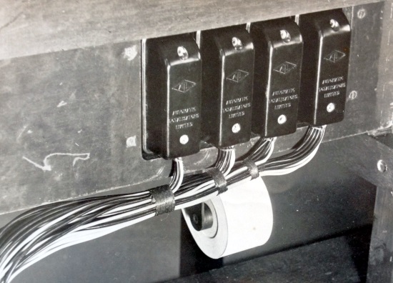
The ATL diamond logo can be seen embossed on each of the covers of these connectors in the image above, as well as the words Automatic on top of Totalisators on top of Limited below each diamond. I think the type of connectors shown in the blueprint drawing at the top of this page, arranged in two parallel rows of ten pads and a third short row or four, in the Adding Unit Fuse Boards and Grand Total Unit Fuse Boards, will have groups of wires attached to them creating leads, with a socket of the type shown in the image immediately above at the other end for each lead, for connection to the associated Grand Total Unit or Horse Adding Unit, which will be nearby. An example can be seen in the image below titled Image of part of the Harringay Julius Tote in Museum Storage. Six Adding Unit Fuse Boards can be seen with their white porcelain fuses along the bottom of the image, with their corresponding Horse Adding Units above them. Normally the plugs of the type shown above, in the image titled Some Plastic Moulded ATL connectors, connected to the TIMs and the Adders, and the cables emanating from the black plugs seen in the image above, probably come from TIMs. The sockets that the black plugs are plugged into, which look like they are permanently attached to a wooden cable tray, will have had cables connected to them inside the cable tray, that ran inside the cable tray to the Horse Units/Adders in the Machine Room with the scanners in the machine room providing the activation pulse for transaction cycles. Transaction cycles are performed by mechanical parts that interact with what is called the Betting Circuit as described in the company document text included below. These connections between the TIMs in the selling houses and the Horse Units in the machine room are described in the next paragraph. The roll of ticket paper seen sitting on a paper dispenser in the image above, confirms that the nearest TIM is not far away, probably on top of the bench vertically above. Below the ticket roll seems to be the floor level, the level at which the operator's feet will rest. Actually, I bet the odd operators foot has rested on the angled wooden support for the cable tray, seen at the right hand lower edge of the image above! An example of a TIM, the J7 is shown in the two images below titled The bottom of a J7 TIM (Issuer) Showing the Horse Halo and Top view of a J7 TIM (Issuer). The slot on the right hand side of the elevated section of the top of the J7 shown in the second mentioned image below, is where the tickets are ejected which requires the paper on the paper roll shown in the image above. The adder in the image below titled A Two Shaft Electro Mechanical Shaft Adder has one of these plugs mounted on the lower rear end of the left hand mounting plate, which is out of view of that image.
The electrical bus consisting of eight conductors, spanning most of the width along the top of the drawing at the top of this page, is attached to the Adding Unit Fuse Boards, labelled from right to left No 1, No 2, No 12, No 13, No 23 and No 24. These Adding Unit Fuse Boards are associated with the Adders which are part of the mainframe in the Machine Room. These eight bus signal conductors are shown exiting the drawing to the right of centre of the horizontal component of the bus where it descends vertically. These culminate in the drawing above, in a down bracket that points to the text To Win Horse Terminals followed by the line on Issuer Terminal followed by Boards and below that 24 Wires in each group. These Issuer Terminal Boards are associated with the TIMs that are in the Selling/Tote Houses. Above the down bracket the conductors are labelled according to the escapement wheel on the Adding Shafts (called Escapement Shafts in the old company document text presented later) in the Adding Units (called Horse Units in the old text) that they connect to. These labels are written vertically below the ends of the related conductors that are shown descending down the page, which terminate in downward pointing arrowheads pointing to the names. They read from left to right, Group 1 ----- 10/- followed by Group 2 ----- 10/- then Group 3 ----- 10/- then Group 4 ----- 10/- then Group 5 ----- 1£ then Group 6 ----- 10/- then Group 7 ----- 1£ and finally Group 8 ----- 5£. The values specified are determined by the number of teeth on the respective escapement wheels of the shaft adders. The more teeth the lesser value recorded as angular displacement on each activation. In the image below titled Julius Poole and Gibson blueprint a drawing of a Grand Total Unit, or what later was called a Grand Total Adder, can be seen to the left of centre in a tall rectangle with the label Grand Total Unit underneath it. I have been told that these Grand Total Units could be used as the Horse Units or Horse Adders, which summed the transactions for a particular runner. I have discovered there are some minor differences between them. If the Grand Total Unit in the blueprint drawing below were used as a Horse Unit, many of these adders would be plugged into the Adding Unit Fuse Boards, labelled from right to left No 1, No 2, No 12, No 13, No 23 and No 24 in the blueprint drawing at the top of this page, as well as all the other implied adder positions between 1 and 24 which are not included in the simplified representative examples, 1, 2, 12, 13, 23 and 24. These Fuse Boards are also shown in detail in the image below titled Julius Poole and Gibson blueprint inside the box on the left hand side with the label Grand Total Fuse Board below it. All this equipment is for the Win Pool and is repeated for the Place Pool as shown in the lower half of the Blueprint Drawing at the top of this page.
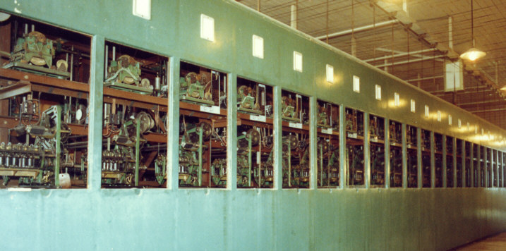
To emphasise what I have just written about the Horse Units and Grand Total Units, when looking at the two electrical buses spanning the width across the top and bottom of the image at the top of this page, keep in mind that this is only representative of a complete Julius Tote. The Julius Totes that I have seen, instead of having the representative six Horse Adders and a Grand Total Adder per pool, or what in the drawing are called Adding Units, they had twenty four Horse Adders plus a Grand Total Adder per pool. The image below shows part of the Place Pool processing equipment of a Julius Tote with the equipment in view repeated on the opposite side of the frame for the Win pool. Each window in the frame has a shaft adder like the one shown below in the image titled A Two Shaft Electro Mechanical Shaft Adder, although that adder is older than the ones in this image immediately below. Additionally there is display generating and driving equipment in each window, part of which is visible above each adder, with more associated equipment not visible in the image below obscured deeper inside the frame. The Adding Unit Fuse Boards mentioned in the previous paragraph are located inside the frame out of sight in the image below, one underneath every adder in each window. These Julius Totalisators were behemoth machines. The medium sized Julius Tote Mainframe in the image below is taller than I am. Let's have a quick look at the mass involved. The shaft adder in the image mentioned, titled A Two Shaft Electro Mechanical Shaft Adder weighs 26Kg. Each adder in the mainframe shown below will have a similar weight and there are 25 adders for the Place Pool on the near side of that mainframe and another 25 on the opposite side each weighing approximately 26Kg giving a total of 1,300Kg. The most highly produced Julius Tote TIM was the J8 and these were the most common TIM attached to the mainframe below and were distributed around the track. Assuming the different models of TIMs on this system weighed approximately the same as the J8, which is 34Kg, then fully populated with the maximum number of TIMs the mainframe below could support that is 128, the TIMs would weigh approximately 4,352 Kg giving a total of 5,652 Kg. This does not include the fuse boards that are associated with each adder, the odds calculating and indicator drive systems that are also associated with each adder, the gear boxes, the indicators, the heavy main drive electric motors for each pool along with the associated drive shafts and pulleys, the reciprocating engine driven generator and its standby generator set that produced the 120V DC supply and other ancillary equipment as well as the miles of cable. Having mentioned the miles of cable, Jack Bell in his Miami Herald article describing the Hialeah Julius tote, wrote that the amount of cable in that Julius Tote system was calculated to be 195 miles! Jack's Miami Herald article can be read in the Automatic Totalisators In America chapter of this website under the subheading Hialeah Park's Australian totalizator, by selecting the Go to the index button in the Navigation Bar at the bottom of this page and then selecting the quoted chapter in the Secondly part of the Index. I well remember being very impressed by the large lead encased power grade cables, running up a wall inside the old Main Tote House at Eagle Farm Racecourse, rising high from ground level disappearing into the very high ceiling in excess of two normal stories to enter the Julius Tote Machine Room on the first floor, that connected the TIMs in all the Tote Houses on the track to the Distributors/Scanners in the front end system in the machine room. Another significant weight that is not included is the Julius Tote front end system, which is out of sight in the image below standing along the right hand wall, includes three tall racks containing the Distributors/Scanners with ancillary equipment which had its own drive motors, part of which can be seen in the image below titled A small section of the Distributor and Relay Switchboard at White City London. Also not included, standing with the three Distributor racks mentioned, are two additional racks of equipment containing what is collectively described as the Main Switchboard in the machine room, in the old company document extract presented below under the heading CONTACTOR CONTROL CIRCUIT/ Drawing No. 3484. As what has not been included in my weight calculation is assuredly heavier than what has, I feel confident to ask the question have you ever heard of a calculator/computer that weighs over 10 Mega grams? Well they used to be prolific around the planet, however they were also clandestine, hidden in machine rooms and tote houses, so it is no surprise if you haven't heard of them, but now you are on the road to find out.
Part of a Julius Tote Mainframe.
The tall rectangle labelled Grand Total Unit to the right of the Grand Total Fuse Board rectangle in the image below titled Julius Poole and Gibson blueprint below, previously mentioned, is an electrical view of the Grand Total Unit or Adder. This electrical view of the Adder in the blueprint drawing below, shows the solenoids that trip the escapement mechanisms allowing the escapement wheels in the adding shafts (escapement shafts in the old text) to rotate and record bets. This is described in the third paragraph above the drawing below titled Julius Poole and Gibson blueprint. Everything relating to the electrical bus at the top of the blueprint drawing at the top of this page for the Win pool, also relates to the similar bus shown at the bottom of the drawing, except it relates to the Place pool and instead of the conductors shown descending to exit the drawing, they rise from the left of centre of the horizontal lower bus. Similarly, they culminate in the blueprint drawing above, in an up bracket that points to the text To Place Horse Terminals on Issuer Terminal Boards 24 Wires in each group only laid out as for the Win bus. These rising conductors are similarly labelled with vertical writing as before except instead of being ordered from left to right, they are ordered from right to left, and read from left to right: Group 8 ----- 5£ followed by Group 7 ----- 1£ then Group 6 ----- 10/- then Group 5 ----- 1£ then Group 4 ----- 10/- then Group 3 ----- 10/- then Group 2 ----- 10/- and finally Group 1 ----- 10/-. The lower bus related Adding Unit Fuse Boards are labelled as before, except they refer to Horse Units that are processing Place pool bets rather than Win pool bets.
I have included a transcription of the 1935 company document titled Automatic Totalisators Limited Description of Electrical Circuit Diagrams below. I have only provided two of the many blueprint images that Prof Bob Doran sent with this description document, as an example of what the Description of Electrical Circuit Diagrams document is describing. Generally, interconnect diagrams like the one at the top of this page provide a high level overview, with a multitude of other drawings providing details of what is contained in each of the different boxes in the interconnect diagram. As an example, as previously mentioned, the interconnect diagram shown at the top of this page makes mention of the Gear Box and a drawing Gear Box Fuse Board Drg. No. 3504. The blueprint drawing below titled Julius Poole and Gibson blueprint, has a number shown in the box at the bottom right corner which is 3503. I note that this blueprint drawing below contains two drawings the first on the left hand side bearing the labels Grand Total Fuse Board and Grand Total Unit, which is consistent with the name of this drawing shown at the bottom edge of the drawing Wiring To Grand Total Units. However, the second drawing on the right hand side bearing the labels Gear Box Fuse Board and Gear Box in the Blueprint drawing below is not mentioned in the title of the drawing and I suspect this is drawing number 3504. It is this drawing that provides the detail of the two boxes labelled Gear Box in the blueprint drawing at the top of this page. Similarly, the left hand drawing bearing the labels Grand Total Fuse Board and Grand Total Unit, of the two in the image below titled Julius Poole and Gibson blueprint, shows the detail of the two boxes labelled Grand Total in the blueprint drawing at the top of this page.
There is no drawing number on the image at the top of this page, however there are distinct similarities between it and drawing number 3509, to which the BETTING CIRCUIT description below, extracted from Automatic Totalisators Limited Description of Electrical Circuit Diagrams, applies. The Adding Unit Fuse Boards, mentioned in the first paragraph of the document extract below, are shown in the blueprint diagram at the top of this page in two rows numbered No 1, No 2, No 12, No 13, No 23 No 24, one across the top of the drawing for the Win Pool and the other across the bottom of the drawing for the Place Pool as described in the second paragraph above and one below, the image above titled Part of a Julius Tote Mainframe. Similarly the Issuer Terminal Boards, also mentioned in the first paragraph of the document extract below, are mentioned in the blueprint diagram at the top of this page in the text To Win Horse Terminals on Issuer Terminal Boards 24 Wires in each group, as well as, To Place Horse Terminals on Issuer Terminal Boards 24 Wires in each group, as identified in the two paragraphs already mentioned in the last sentence.
In the second paragraph of the BETTING CIRCUIT description below it mentions the diagram showing a Win and Place Machine which also applies to the blueprint diagram at the top of this page, the top half being the Win Machine and the bottom half the Place machine. Additionally in this paragraph below, it mentions The Grand Total Unit and three horse units are shown for each machine, which is more than covered by the blueprint drawing at the top of this page. The Grand Total Units are attached to Grand Total Unit Fuse Boards, and one of these Fuse Boards, which is for the Win pool, is represented by the box top centre in the blueprint drawing at the top of this page, below the heading WIN MACHINE with the label Grand Total above it. Another one of these Fuse Boards, which is for the Place pool, is represented by the box bottom centre in the blueprint drawing at the top of this page, above and to the right of the label PLACE MACHINE at the bottom edge of the drawing, with the label Grand Total inside the box. Regarding the three horse units are shown for each machine however, the blueprint drawing at the top of this page differs from drawing 3509 being described below, as it shows six horse units for each machine labelled No 1, No 2, No 12, No 13, No 23 and No 24, instead of three in drawing 3509. A second discrepancy in this second paragraph below the next heading, lies in the statement these units are shown with two escapement shafts and twelve escapements. Both the drawing above and the description below refer to Two Shaft Adders, or Units as referred to here, meaning they both have two escapement shafts, however the the ones in the drawing above have six escapements on one shaft and two on the second whilst the description below refers to Horse Adders/Horse Units with six escapements on both shafts. The fact that the drawing above relates to eight escapements and not twelve can be determined from the electrical bus cables grouped together under the labels To Win Horse Terminals on Issuer Terminal Boards 24 Wires in each group and To Place Horse Terminals on Issuer Terminal Boards 24 Wires in each group and individually identified as Group 1 through Group 8. Each of these eight Group Lines relates to an escapement wheel on every one of the respective Shaft Adders, or Horse Units as they are referred to in this text, in a specific installation. The use of the word Group in these escapement wheel bus lines relates to the fact that each escapement wheel in a shaft adder caters to a group of TIMs or Ticket Issuing Machines, which in the above drawing are called Issuer Terminals or just Issuers, which contain Issuer Terminal Boards as referred to in the drawing above in the text To Win Horse Terminals on Issuer Terminal Boards 24 Wires in each group. A group of TIMs were multiplexed by the Julius Tote Front End System containing devices called Distributors or in latter years Scanners. I have seen Distributors cater for up to sixteen TIMs on a single escapement. The number of TIMs/Issuers supported is dependent on the era that the Julius Tote was manufactured and the requirements of the specific system.
The third paragraph below the next heading mentions Three groups of Issuers and the corresponding Distributors and Relays that appear in Drawing No. 3509 and this level of detail is not shown in the Drawing at the top of this page. There is however, a reference to the Distributors in the blueprint drawing at the top of this page that reads 8 Wires to common Rings of the 8 Win Distributors through 14 Ohm Resistors. In the image below titled Julius Poole and Gibson blueprint a drawing of a Grand Total Unit, or what later was called a Grand Total Adder, can be seen to the left of centre in a tall rectangle with the label Grand Total Unit underneath it. If the Grand Total Unit in this blueprint drawing below were used as a Grand Total Unit as the name implies, and not as a Horse Unit, as previously suggested is possible, then two of the Grand Total Horse Units in the blueprint drawing below would be utilised. The first is used to calculate the Win Pool grand total and would be plugged into the Grand Total Unit Fuse Board, represented by the box top centre in the blueprint drawing at the top of this page, below the heading WIN MACHINE as mentioned in the previous paragraph. Eight conductors can be seen drawn descending from this Grand Total Unit Fuse Board culminating in a down bracket pointing to the previously mentioned text 8 Wires to common Rings of the 8 Win Distributors through 14 Ohm Resistors below. The second is used to calculate the Place Pool grand total and would be plugged into the Grand Total Unit Fuse Board, represented by the box bottom centre in the blueprint drawing at the top of this page, above and to the right of the label PLACE MACHINE at the bottom edge of the drawing which is also mentioned in the previous paragraph. Similar to the Win pool Grand Total Unit, there is a group of eight conductors rising from this Place pool Grand Total Unit box, from pads belonging to a connector represented inside the box, which terminate in an upward pointing bracket pointing to the text 8 Wires to common Rings of the 8 Place Distributors through 14 Ohm Resistors.
The sixth paragraph below the next heading mentions the Control Room Switchboard. There is an image of such a switch board at the bottom of this page. This switchboard was located at Hialeah racecourse, which is in Miami in the United States.
Following is the transcription of the company document titled Automatic Totalisators Limited Description of Electrical Circuit Diagrams:
BETTING CIRCUIT./ Drawing No. 3509.
This drawing shows the Betting Circuit in a diagrammatic form. To simplify the diagram the Issuer Terminal Boards and Adding Unit Fuse boards have been omitted although certain pieces of the equipment on the latter have been shown.
The diagram shows a Win and Place Machine. The Grand Total Unit and three horse units are shown for each machine and these units are shown with two escapement shafts and twelve escapements.
Three groups of issuers, each group containing two issuers are shown together with the corresponding Distributors and Relays.
A group of issuers may consist of any number of issuers up to a maximum of eight, all of which sell tickets of the same value and which are connected together to one escapement on the adding units. For convenience the issuers are usually numbered to correspond with the escapement to which they are connected, that is issuers connected to escapement No. 2 are numbered 21 to 28, issuers connected to Escapement no. 4 are numbered 41 to 48 and issuers connected to Escapement No. 12 are numbered 121 to 128 and so on.
The diagram my be extended to cover any number of horse units each of which may have any number of escapements and escapement shafts, the principle being identical in all cases.
On the Main Switchboard there is a Main Betting Circuit switch and fuses. From the - side of this switch a common feed is taken to the common side of a bank of 'Starters' switches on the Control Room Switchboard in the Manager's Office, there being one switch for each horse unit.
From the other side of each of these switches a lead is taken to the "Betting Circuit" switch on the corresponding Win and Place Horse Unit Fuse Boards.
The circuit through each horse unit is then as follows -. Through the Betting Circuit Switch and Fuse and through the normally closed contacts of the Escapement Cutout Relays (the operation and purpose of these relays is described elsewhere) to the common side of the escapement fuses, there being one fuse for each escapement and thence to the escapements.
From the escapements the circuit now proceeds to the corresponding contacts on the Horse Selector Segments of the corresponding issuers, that is the wire from No. 1 escapement on No. 1 Win Horse Unit is looped into the No. 1 Contact on the Win Horse Selector Segments of all issuers in No. 1 Group and so on.
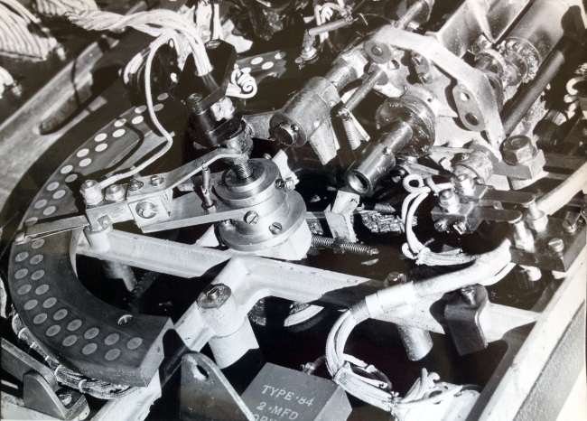
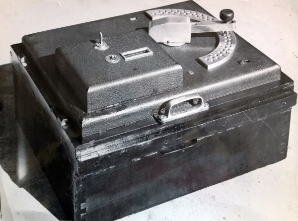
I have included the following image as an example of the 'Horse Selector Segments' mentioned above which in later years was called the Horse Halo. The arc seen with contact studs on it in the image below, was used to select the runner number required for the transaction. The TIMs (Ticket Issuing Machines) is what are called Issuers in the paragraph from the Description of Electrical Circuit Diagrams document above.
The bottom of a J7 TIM (Issuer) Showing the Horse Halo
Webmaster's notes
I have also included the image below to show what the top side of the J7 TIM looks like. The images above and below are not part of the Description of Electrical Circuit Diagrams document. These images show the business end of a totalisator system, where the totalisator tickets are sold. The largest Julius Totalisator I am aware of was installed in White City London commencing operation in 1933 which had 320 TIMs and the second largest was in Longchamps Paris commencing in 1928 with 273 terminals. The arm that sweeps across the arc, or Horse Halo, in the image above is connected to the runner selector handle seen on the top of the J7 on the right hand side in the image below.
The next paragraph in the continuation of the extract from the Description of Electrical Circuit Diagrams company document, which follows these notes, mentions the collecting brush which picks up the contacts on the Horse Selector Segments. The collecting brush can be seen in the image above about half way around the Horse Halo. The spindle the runner selection handle is anchored on in the image below, is at the centre of the runner selection semicircular plate with the runner locating holes in it and is the same spindle seen in the image above, which is a bottom view of the spindle. In the image above the end of the arm attached to this spindle has two metal strips attached, each extending to a position above their respective arc of contact pads. Each strip has a protruding electrical contact at its end, which makes contact with a selected contact pad on the associated arc of pads. These metal strips with the electrical contacts at their tips are the collecting brushes, one for each of the two arcs of contact pads. The outer arc of contact pads are for the Win Pool and the inner arc of contacts are for the Place Pool and these pads correspond with the locating holes in the runner selection semicircular plate on the top of the J7 shown in the image below. The Win or Place pool is selected by the knob on top of the runner selection arm in the image below, depending on whether the knob is pushed longitudinally along the arm to its outer or inner limit. Usually, there are as many studs in each arc as the maximum possible number of runners in a race plus one for printing test tickets.
The HANDLE LOCK SWITCH ON ISSUER, is the title of item 7 in the list of 14 items below, extracted from the company document titled Description of Electrical Circuit Diagrams. The HANDLE LOCK mechanism can be seen in the image below. It involves the knob on top of and at the right hand end of the runner selector arm, which when pressed pushes a pin into a locating hole to lock the handle on the selected runner and pool closing the HANDLE LOCK SWITCH, to stop the knob moving once a selection is made. This holds the brush on top of the contact in the horse halo shown in the image above and keeps the contacts in place for the duration of the transaction cycle at the end of which the HANDLE LOCK SWITCH is opened and the knob pops back out restoring the pool selection knob and runner selection arm movement. The knob on the top of the runner selection handle can be moved a short distance radially along the runner selection arm. In the outer position it selects the Win Pool and in the inner position it selects the Place Pool. The slot in which the knob moves radially along the arm can be seen in the image below to the right of the knob.
The ISSUER TRIP COIL AND TRIP SWITCH is the title of item 8 in the list of 14 items below, extracted from the company document. There is a switch near the right hand edge of the image above at about mid height level. At or just below mid height level, touching the right hand edge of the image above, is the corner of what looks like a square black Lego piece. Being black it contrasts with the bright coloured frame of the J7 to which it is attached. The demarcation line between the two can be seen descending to the left from the right hand edge of the image above, just below mid height level, black on top bright grey almost white below. Like a Lego piece, the black piece in the image above is probably an insulator as it holds electrical connections. Instead of the four raised cylindrical connector sections on top of a Lego piece, there are four screws in similar positions instead. The two pan heads of the right hand pair of screws can be seen flush with the surface of what I will call the square insulator instead of relating it to a Lego piece. These screws secure the square insulator to the frame. The threaded section of the two left hand screws can be seen rising above the square insulator and nuts can be seen on the threaded shaft section of the screws, which are in contact with the square insulator securing the screws to the insulator. Above the top of these two screws are the tips of two metal strips, which are not in contact with the screws below, extending from two separate anchor points at the left hand ends of the strips. These anchor points are on top of a similar looking square insulator, except that there are only two screws on the top surface, each passing through its own rectangular metal strip with a nut on each screw clamping the respective rectangular strips and their protruding metal strips underneath, to the square insulator. On top of each of these nuts on each screw are a pair of washers with another nut on top of each pair of washers clamping the washers together. A conductor is clamped between each of the pairs of washers. The outer insulation of these conductors can be seen on the left hand side of each of the pairs of nuts on each screw. This left hand upper square insulator is capable of being rotated clockwise, such that after rotating, the protruding metal strips make contact with their respective screw shafts beneath them and this action is the closing of a two pole single throw switch. I think this is the TRIP SWITCH mentioned in item 8 of the list. From another image I have not included, taken from a perspective top right hand corner of the image above looking back at the Trip Switch, the pivot for this rotation of the top contacts of the switch can be seen. Additionally in this other perspective, an activating rod for this rotation can be seen attached to a plate, which is attached to the side of the square insulator, on the opposite side to the side visible in the image above. Below the first described square insulator, which is at the right hand edge of the image above, is a coil behind the downward extension of the bottom left screw, which can be seen extending below this insulator. It is not possible to clearly see this coil at the resolution and size of the image above however it can just be made out by enlarging the above image. It is very clear in a high resolution version of this image. I think this coil is part of the solenoid mentioned in item 8, the plunger of which is probably attached to the activating rod just mentioned that controls the Trip Switch. Additionally in the image not included here showing the different perspective, a large coil can be seen, which is located off the right hand side of the image above close to the top of the image. A shadow can be seen on the side of the motor near the top right corner of the image above and this I think is cast by this large coil and I think this is the Trip Coil mentioned in item 8.
The ISSUER SWITCH ON ISSUER, is the title of item 9 in the list of 14 items below, extracted from the company document. There are two switches seen on the top of the J7 shown in the image below. I think the switch that cuts out the issuer as mentioned in item 9, is the switch at the bottom right hand corner of the J7 in the image below. There is however, a second switch on the J7 that can be seen on the raised section of the top of the machine, to the left of the ticket issue slot. The key seen behind this second switch is probably the key that locks the lid of the machine down so that removing the top cover of the machine can be restricted to technical staff only, which were called mechanics or engineers at the time of the Julius Totalisators or technicians or engineers in the electronic/computer era.
Following is the continuation of the transcription of Automatic Totalisators Limited Description of Electrical Circuit Diagrams:
Top view of a J7 TIM (Issuer)
The circuit through each Issuer is then as follows. From the collecting brush which picks up the contacts on the Horse Selector Segments through the Handle Lock Switch (closed only when the handle is locked down) through the Trip Coil, through the trip switch (normally closed when the Issuer is stationary), through the Issuer Switch (Tumbler Switch on Issuer Cover Plate) to the Win - Place Selector Switch.
From each Issuer two wires (one for Win and one for Place) are taken from the Contacts of the Win-Place Selector Switch to the Double Pole Issuer Common Switches on the bottom of the Distributor and Relay Switchboard and thence through the coils of the corresponding Relays to the Distributor Contacts. There are a pair of relays (one Win and one Place) for each Issuer and a pair of Distributors (one Win and one Place) for each Group of Issuers and each Distributor has 8 contacts corresponding to the 8 issuers in the group.
From the Common ring of each distributor, leads are taken to the corresponding escapement magnets on the two Grand Total Units.
The circuit through the Grand Total Units is as follows. Through Escapement magnet and corresponding escapement fuse, through contacts of Escapement Cutout Relay and through Betting Circuit Fuse and Switch.
From the Betting Circuit Switch of each Grand Total Fuse Board a lead is taken to the contacts of the Win and Place Contactors on the Main Switchboard and thence through those contacts to the + side of the Main Betting Circuit Switch and Fuse.
Webmaster's notes:
In the second paragraph below the image above, it mentions Issuer Common Switches on the bottom of the Distributor and Relay Switchboard. These Switches Distributors and Relays can be seen in the image below, although the White City Distributor and Relay Switchboard seen in that image, was laid out a little differently to the one being described in the old company document extract above. The Issuer Common Switches are not at the bottom of the distributor switchboard panels shown below, the distributors are at the bottom instead. The equipment shown in the image below is arranged into repeated columns and in that image only the centre column is completely in view. Across the top of the image below are a row of cut out relays or what today would be called circuit breakers and there are six of them in the central column. Below this in the central column, is a matrix of switches six across and eight down and these are the Issuer Common Switches.
The Grand Total Fuse Board, mentioned in the last paragraph before these notes, can be seen in the tall oblong rectangle, with an underlined label below it of the same name, next to the left hand side of the blueprint drawing below titled Julius Poole and Gibson blueprint. The third paragraph below the image above, relating to the Betting Circuit, mentions leads are taken to the corresponding escapement magnets on the two Grand Total Units. This connection marks the beginning of the path through the Grand Total Fuse Boards and the Grand Total Units, which can be traced through the drawing on the left hand side of the Julius Poole and Gibson blueprint below. I have chosen to trace the path relating to escapement number 7 in the Grand Total Unit, as it is easier to describe that path through the drawings. One of the leads mentioned which corresponds with escapement number 7, enters the Grand Total Fuse Board shown in the tall rectangle nearest the left hand edge of the Julius Poole and Gibson blueprint below, via a connector shown at the bottom of this rectangle with the underlined label text Escapement Terminals below it at the very bottom of the rectangle, which is hard to read without enlarging the image. The obvious part of this connector appears as two rows of ten small circles one on top of the other, across the bottom of the rectangle. These small circles represent electrical connections between the external wiring and the internal wiring of the Grand Total Fuse Board. The right hand small circle of ten in the top row, has the number 7 below it indicating it belongs to escapement number 7. The connection then travels right in the drawing and exits the Grand Total Fuse Board rectangle and then rises to a position higher than the top of the Grand Total Fuse Board rectangle where it turns right to enter the second rectangle in this drawing. This second rectangle is taller than the first, in this drawing on the left hand side of the Julius Poole and Gibson blueprint below and is labelled Grand Total Unit below the rectangle. From here the conductor continues right near the top of the Grand Total Unit rectangle to about half way across it and then descends a short distance to join the right hand coil of two, which constitute the number 7 escapement electromagnet, represented as two medium sized circles in the blueprint drawing below. The fourth paragraph below the image above starts with The circuit through the Grand Total Units is as follows. Through Escapement magnet and ... We have just arrived in this example at the Escapement magnet mentioned in the company document extract above. Following the circuit in the Blueprint Drawing below, the two coils are shown electrically connected together by a wire joining the bottom of the two circles representing the coils. It is through this wire that we manage to pass Through Escapement magnet as mentioned in the fourth paragraph below the image above. The circuit continues up out of the left hand coil and turns left immediately below the top of the Grand Total Unit rectangle, continuing left across the top and exiting the rectangle on the left hand side, then descending before turning left again to re-enter the Grand Total Fuse Board rectangle in the top right quadrant. Here it continues left a short distance and then descends to join the left hand side of a fuse labelled 7-£1, specifying this as the fuse for escapement 7, which registers £1 bets for every activation of the associated escapement wheel, which is advanced a tooth by the electromagnet the Betting Circuit has just been through, by activating its associated escapement mechanism. There is a label in the blueprint drawing below, above this fuse that reads: Escapement Fuses. We have now reached the point in the circuit description text in the fourth paragraph below the image above, that states ... and corresponding escapement fuse. The Betting Circuit continues through the fuse and then from the right hand end of the fuse downwards, passing through a small connection circle with another fuse, continuing downwards then turns left for a short distance and joins another small circle indicating a connection with a switch. Here the betting circuit does not descend further with the continuous line but travels from the small connection circle down the arm of the switch represented by a descending broken line leaning slightly left of vertical. We have just passed through the Escapement Cutout Relay mentioned in the fourth paragraph below the image above. In the blueprint drawing below this is labelled Alarm Relay, which is difficult to read. It is called the Alarm Relay as an Escapement Cutout raises an alarm. In other words, both names refer to the same relay. This broken line switch arm belonging to this relay now joins another connection circle in the blueprint drawing below, which is also the switch arm pivot point, where the Betting Circuit leaves the switch heading right a short distance then up before turning left a short distance, descends and turns left again to meet a connection with another arm of a similar switch. The circuit continues left past the connector, not entering this second switch, rises, turns left, rises again and turns left then rises again a final time and turns left joining the top of another fuse. This is the Betting Circuit Fuse mentioned near the end of the fourth paragraph beneath the image above. The Betting Circuit passes down through this fuse continues down then turns right and down again a short distance and joins another connection circle. This has a horizontal broken line joining another connection circle to the left of the first. This broken line represents the Betting Circuit Switch and has the label Betting Circuit Switch below it and is the end of the description in the fourth paragraph below the image above, which reads ... and through Betting Circuit Fuse and Switch. From the left hand end of the switch the betting circuit continues downwards joining another connection circle which is part of the original connector we started with. This connector was described at the beginning of this paragraph as the obvious part of this connector appears as two rows of ten small circles. There is another, not so obvious, row of four small circles above the two rows described. It is the third connection circle in this upper short row of the connector that the Betting Circuit exits the Grand Total Fuse Board on, which is identified in the Blueprint drawing below with the words Betting Circuit on top of the word Terminal and an arrow pointing down to the right from this word to the identified connector terminal in this connector. As stated in the last paragraph before these notes, from this connector contact, which is attached to the Betting Circuit Switch the betting circuit extends further through the following means: a lead is taken to the contacts of the Win and Place Contactors on the Main Switchboard.
Item 3 in the list below, is the BETTING CIRCUIT SWITCH ON HORSE UNIT FUSE BOARDS. The Horse Units are almost the same as the Grand Total Units, and the Betting Circuit Switch mentioned in my last paragraph above relating to the Grand Total Fuse Board is the same as the one in the Horse Unit Fuse Boards mentioned below. N.B. The name Horse Unit in these old documents is synonymous with the name Adding Unit.
Following is the continuation of the transcription of Automatic Totalisators Limited Description of Electrical Circuit Diagrams:
The function and operation of the various switches, relays etc. in the circuit are as follows.
- MAIN BETTING CIRCUIT SWITCH AND FUSES ON MAIN SWITCHBOARD.
This switch controls the whole of the betting circuits on both poles. This switch is closed at the beginning of the day and is kept closed during the whole of the day.
- STARTERS SWITCHES ON CONTROL ROOM SWITCHBOARD.
These switches control the negative supply to each horse unit and enable the Manager to cutout all units except those for the actual 'Starters' in the Race. This prevents tickets being sold on Scratched horses. These switches are operated by the Manager before each race.
- BETTING CIRCUIT SWITCH ON HORSE UNIT FUSE BOARDS.
This switch controls the negative supply to the corresponding horse unit and enables the Mechanic to cutout a Horse Unit if any trouble occurs and so prevent further betting on that Horse until the trouble has been fixed. These switches are left closed for the whole of the day.
- ESCAPEMENT CUTOUT RELAYS ON ADDING UNIT FUSE BOARDS.
These relays automatically trip and interrupt the Betting Circuit if the driving gear to the adding unit fails. The operation of these Relays is described elsewhere.
- ESCAPEMENT MAGNETS ON HORSE UNITS.
These magnets operate the adding escapements which record each bet on the appropriate horse and Grand Total Unit.
- HORSE SELECTOR SEGMENT ON ISSUER.
These selector segments operate with a moving contact arm which is controlled by the Selector Handle of the Issuer and so connect the Issuer to the Horse Unit corresponding to the Horse for which the Ticket is to be issued.
- HANDLE LOCK SWITCH ON ISSUER.
This switch is only closed when the Selector Handle has been pressed and locked into the hole on the Selector Plate corresponding to the Horse for which the ticket is to be issued. This switch remains closed and the handle is locked down until the cycle of the Issuer has been practically completed.
- ISSUER TRIP COIL AND TRIP SWITCH.
This Trip Coil is in series with the escapement magnets. When the Betting Circuit is completed the appropriate Horse and Grand Total Escapement Magnets and the Issuer Trip Coil are all energised at the one time. The Trip Coil operates a solenoid plunger which at the end of its stroke, opens the Issuer Trip Switch and so interrupts the Betting Circuit and at the same time the plunger releases a mechanical latch on the Issuer and closes the circuit for the magnetic clutch and the Issuer then prints and issues the ticket.
The trip coil plunger is arranged so that it is slower in operation than the escapement magnets so as to ensure that the trip switch is not opened before the escapement magnets have operated.
- ISSUER SWITCH ON ISSUER.
This is a tumbler switch on the Issuer Cover and enables the Seller to cutout the issuer when she leaves it unattended.
- WIN-PLACE SELECTOR SWITCH ON ISSUER.
This switch is operated by the Issuer Selector Handle and serves to connect the Issuer to either the Win or Place Adding units as required.
- ISSUER COMMON SWITCHES ON DISTRIBUTOR SWITCHBOARD.
There is one of these switches for each Issuer and they enable any issuer to be cut out from the Machine Room when it is not in use and so prevent the unauthorised use of the issuers.
- DISTRIBUTORS.
There are a pair of Distributors for each Group of Issuers, that is for each Escapement, one for Win and one for Place. Each distributor has 8 contact studs and a common contact ring and a contact arm is continually rotated thus connecting the ring to each stud in turn. The distributors are driven at a speed of about 90 revolutions per minute by means of a motor and suitable gearing.
The eight studs are connected to the 8 issuers in the group and the common ring is connected to the corresponding Grand Total Escapement, so that the distributor serves to connect the 8 issuers in the group to the one escapement magnet in turn, that is the circuit is only completed through one issuer at a time even if the whole 8 issuers have their handles depressed at the same instant. This enables one escapement to record the bets from 8 issuers.
When an issuer handle is depressed, the Betting Circuit is not completed until the Distributor Contact arm reaches the stud corresponding to that issuer. The Issuer Trip Coil plunger is arranged so that it will operate and so open the Betting Circuit again before the Distributor reaches the next Contact stud, thus enabling the escapement to make its return stroke and be ready to record the bet from the next issuer in the group if its handle has been depressed.
- RELAYS ON DISTRIBUTOR BOARD.
There are a pair of relays, one for Win and one for Place for each Issuer.
These relays serve to provide a definite time for the Issuer Trip Coil to function even if the Issuer Handle is depressed just as the Distributor Contact arm is leaving the Contact Stud corresponding to that Issuer.
The relay coil is connected in series with the Trip Coil and escapement magnets and so is energised when the Betting circuit is completed. The relay contacts are arranged so as to short circuit the distributor when the relay closes. Thus the Betting Circuit is maintained when the Distributor Contact arm leaves the contact stud and is only broken by the Issuer Trip Switch. The relay is very quick in operation and will close and so maintain the circuit if the Issuer Handle is depressed just as the Distributor Contact arm is leaving the contact stud.
- WIN AND PLACE CONTACTORS ON MAIN SWITCHBOARD.
These Contactors control the positive supply to the two Grand Total units and thus no betting can occur when they are open.
They are magnetically operated and only close when the Managers and Mechanics Control Switches are closed. They are also automatically opened by the operation of the Stewards switch. The circuit controlling these Contactors is described elsewhere.
Webmaster's notes:
In item 2 in the list above the Starters Switches, which control the negative supply to each horse unit are mentioned. These negative supply conductors are shown in the drawing at the top of this page. They are easy to locate as they are represented by the highest horizontal line spanning most of the width of the drawing running across the top of the top row of boxes. These conductors can be seen exiting the drawing represented by a vertical line, an extension of the horizontal line, passing down the left hand side of the top row box labelled No 12. This has two lines of text, rotated anticlockwise 90 degrees to orient them vertically, at the bottom of the vertical line that reads 24 Wires to Starters Switches on the left and on Control Room Switchboard to the right. The horizontal component of these lines can be seen passing through the Gear Box and Grand Total boxes, amongst the top row of boxes, without any connection. However, there are connections in each of the sample Horse Units labelled No 13, No 23 and No 24 to the left of the vertical component of the line representing these conductors and No 1, No 2 and No 12 to the right. As the highest Horse Unit number in the drawing at the top of this page is 24, amongst the six sample Horse Unit numbers shown for the Win Pool in the drawing, we can deduce that this is the highest Horse Unit number. Additionally, 24 was a common maximum field size for races, certainly in my time, although much higher field sizes were prevalent in the earlier Julius Totalisators. This maximum field size of 24 is consistent with the labelling for these conductors in the drawing above, the first line of text reading 24 Wires to Starters Switches, which is one for each of the Horse Units.
As item 2 in the list above refers to scratchings, which I will add includes runners in excess of the highest numbered horse in a race, it is clear that if a horse is a non runner, then there should be no sales on either the Win pool or the Place pool on these runners. This can be seen facilitated in the drawing at the top of this page. For every connection of these conductors from the Starters Switches, that connect to a terminal in each of the Win pool Horse Units, the connection is shown for each Win pool Horse Unit, extending further down the drawing to a similar connection in the counterpart Horse Unit belonging to the group of Place pool Horse Units. These Place pool Horse Units are represented by the boxes labelled No 1, No 2, No 12, No 13, No 23 and No 24 from right to left across the bottom of the drawing above. In other words for any of the 24 starters switches that are left open, the Win pool and Place pool corresponding adders for that runner will be disabled.
Item 4 in the list above is titled ESCAPEMENT CUTOUT RELAYS ON ADDING UNIT FUSE BOARDS. As these boards are almost identical to the Grand Total Fuse Board the Escapement Cutout Relay mentioned can be seen in the blueprint drawing below, only it is labelled Alarm Relay as described in the paragraph above the blueprint drawing below titled Julius Poole and Gibson blueprint.
Item 5 in the list above is titled ESCAPEMENT MAGNETS ON HORSE UNITS. These Escapement Magnets mentioned, which are electromagnets, are part of what today is called a solenoid. the escapement trip mechanisms are activated by solenoids as a result of pulses from the TIMs sequenced by the Distributors. These Escapement Magnets/solenoids, are described in the third paragraph above the image below titled Julius Poole and Gibson blueprint.
Item 12 in the list above is titled DISTRIBUTORS. I have included the image below that shows these distributors:
A small section of the Distributor and Relay Switchboard at White City London
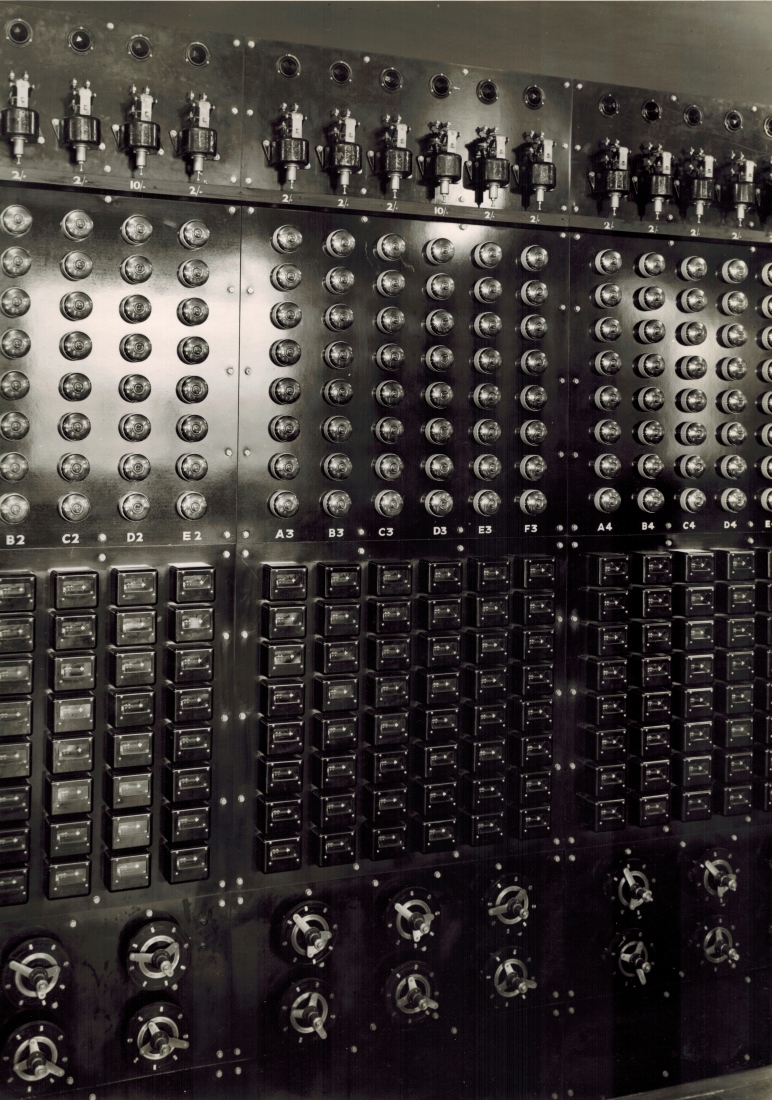
In item 12 of the list above, the first sentence reads: There are a pair of Distributors for each Group of Issuers, that is for each Escapement, one for Win and one for Place. The image above only shows a small section of the Distributor and Relay Switchboard, so that the detail can be seen. To see the complete Switchboard, click on the image at the top of this page, scroll up to the heading in the Photo Gallery index starting with White City Stadium London 1933 - then scroll down and select the thumbnail with the associated text starting The main switch board.... Back to the image above, these Distributors are the circular devices at the bottom of that image, one row for the Win Pool and the other row for the Place Pool. Item 12 also states Each distributor has 8 contact studs and a common contact ring and a contact arm. The common contact ring is the continuous ring around the centre of the scanner and the 8 contact studs can be seen arranged in a circle around the continuous ring. The contact arm is a little different in the image above. In many installations, like the one being described, there is a single long contact arm spanning the diameter of the outer ring of the distributor, rotating about its centre. However in the image above there are three contact arms, pivoted at the central hub and radiating out separated from each other by 120 degrees. Two of the arms are shorter than the third and are in contact with the inner ring as the arm assembly rotates. These arms have surfaces that make electrical contact with the continuous ring. The third arm is longer and it makes electrical connections with the individual studs in the broken ring as this arm passes over them effectively connecting the continuous ring to the stud as the arm passes over them.
Item 13 in the list above is titled RELAYS ON DISTRIBUTOR BOARD. The first sentence reads: There are a pair of relays, one for Win and one for Place for each Issuer. The relays are seen in banks of equipment above each group of distributors. Looking at the centre bank of six distributors, three in the top row and three underneath, there is a matrix of six across by eight down relays, located directly above the six distributors. Each column of eight relays provides one relay per stud on the column associated distributor and the six columns of relays are one for each distributor in the group of six.
Item 14 in the list above is titled WIN AND PLACE CONTACTORS ON MAIN SWITCHBOARD. The wires from these contactors can be seen in the drawing at the top of this page. In the Grand Total box in the middle of the top row of boxes, attached to the third pad from the left in the top row of four pads in the connector shown at the bottom of this box, there is a conductor seen descending through the bottom of the box and crossing the horizontal bus of eight conductors and terminating in a + sign. Below this sign there is the vertically oriented text associated with this conductor, which reads To Win Contactor on Main on the left with Switchboard on the right. Similarly, in the Grand Total box near the middle of the bottom row of boxes, attached to the third pad from the right in the bottom row of pads, in the connector shown at the top of this box, there is a conductor seen rising through the top of the box and crossing the horizontal bus of eight conductors and terminating in a - sign. Above this sign there is the vertically oriented text associated with this conductor which reads To Place Contactor on on the left with Main Switchboard on the right. These are the two wires that implement the statement These Contactors control the positive supply to the two Grand Total units ... in item 14 in the list above. Another such connection to these contactors can be seen in the Gear Box box in the top row of boxes, attached to the third pad from the right in the bottom row of pads, in the connector shown in this box. There is a conductor seen descending through the bottom of the box and crossing the horizontal bus of eight conductors and terminating in a + sign. Below this sign there is the vertically oriented text associated with this conductor which reads To Win Contactor on the left with on Main Switchboard on the right. Similarly, in the Gear Box box in the bottom row of boxes, attached to the third pad from the left in the top row of pads of the connector shown at the top of this box, there is a conductor seen rising through the top of the box and crossing the horizontal bus of eight conductors and terminating in a + sign. Above this sign there is the vertically oriented text associated with this conductor which reads To Place Contactor on on the left with Main Switchboard on the right.
Following is the continuation of the transcription of Automatic Totalisators Limited Description of Electrical Circuit Diagrams:
To illustrate the operation of the Betting Circuit more clearly, assume that No. 22 Issuer is to Issue a 'Win' Ticket on No. 3 horse. The circuit will then be as follows-
- From - pole of Main Betting Circuit Switch on Main Switchboard to common side of Starter Switches on Control Room Switchboard.
- Though No. 3 'Starter' Switch (assuming that No. 3 Horse is a Starter and the switch has been closed) to the Betting Circuit Switch on No. 3 Win Horse Unit Fuse Board.
- Through Betting Circuit Switch, Betting Circuit Fuse, Escapement Cutout Relay Contacts, No. 2 Escapement Fuse to No. 2 Escapement.
- From No. 2 Escapement to No. 3 Contact on the Win Horse Selector Segment of No. 22 Issuer.
- From this contact through Horse Selector Brush (which will be on this Contact if Handle has been depressed in No. 3 Hole in the Selector Plate and with the Handle Knob in the outer or 'Win' position) through Handle lock Switch (which will close when Handle is depressed) through Trip Coil, Trip Switch, Issuer Switch, and through Win-Place Selector Switch to 'Win' Contact (Switch will be in Win Position if selector handle is in Win Position)
- From Win Contact on Issuer through Win Pole of No.22 Issuer Common Switch on Distributor Board through coil of No. 22 Win Relay, to No. 2 Stud of No. 2 Win Distributor.
- From Common ring of No. 2 Win Distributor to No. 2 Escapement on Win Grand Total Unit through No. 2 Escapement fuse, through Escapement Cutout Relay Contacts, Betting Circuit Fuse and Betting Circuit Switch.
- From Betting Circuit Switch on Win Grand Total Unit to Contacts of Win Contactor (which will be closed if Machine is open for betting) and thence to + side of Main Betting Circuit Switch.
When the Issuer Handle is depressed therefore, the circuit is complete except through the Distributor which completes the circuit as soon as it reaches No. 2 stud. No. 22 Win Relay will then instantly close and so maintain the circuit. The bet will be registered No. 2 Escapement of the Win Grand Total Unit and No. 3 Win horse Unit and the Issuer Trip Coil will function to start the Issuer and open the Betting circuit again.
So ends the Betting Circuit Drawing No. 3509 extract.
The Common ring, mentioned in item seven in the list of eight items above and prior, is also mentioned in the drawing at the top of this page. In that drawing, below the underlined title WIN MACHINE top centre, is a box labelled Grand Total. Eight wires can be seen descending from this box numbered 6 3 5 2 4 1 8 7. They are grouped together in a downward pointing bracket to the text 8 Wires to common on top of Rings of the 8 Win on top of Distributors above through 14 Ohm Re- above sistors, which put together reads 8 Wires to common Rings of the 8 Win Distributors through 14 Ohm Resistors. Below this in the blueprint drawing at the top of this page, is a similar box labelled Grand Total above the words PLACE MACHINE with Eight wires rising from this box numbered 7 8 1 4 2 5 3 6 which are grouped together with an upward pointing bracket to the text 8 Wires to common Rings of the 8 Place Distributors through 14 Ohm Resistors. These boxes labelled Grand Total in the image at the top of this page, represent the Grand Total Fuse Boards, shown in the blueprint drawing below titled Julius Poole and Gibson blueprint, for the Win and Place pools. There is a detailed drawing of a Grand Total Unit and a Grand Total Fuse Board, on the left hand side of the image below labelled Julius Poole and Gibson blueprint, which can perform the function of either the Win or the Place Grand Total Unit. The 8 wires from the common rings, are connected to the 8 pads in the connector above the label Escapement Terminals at the bottom of the box labelled Grand Total Fuse Board in the blueprint drawing below. The Grand Total Units with their associated Fuse Boards, like the one shown in the blueprint drawing image below are wired to the common ring of the distributors as the Grand Total Unit for a particular Pool must count all transactions for that pool, no matter which runner has been selected by the TIM, which is presently being scanned by the distributor arm passing over the stud the TIM is connected to. This is discussed further in the paragraph after the next. The Grand Total Unit in my time was called a Grand Total Adder.
As a reminder, the left hand side of the blueprint drawing below titled Julius Poole and Gibson blueprint, which is drawing number 3503, shows detail of the Grand Total Fuse Board and the Grand Total Unit. The right hand side of the blueprint drawing below shows the Gear Box Fuse Board and the Gear Box. The Gear Box Fuse Board for the Place pool is represented in the image at the top of this page as a box to the right of the bottom Grand Total box for the Place pool labelled Gear Box. Below this box in the image at the top of this page, is the text Gear Box Fuse Board Drg. No. 3504, just above the bottom edge of the image, which is shown in the bottom right hand quadrant of the image below titled Julius Poole and Gibson blueprint. I presume the right hand side of drawing 3503 below became drawing 3504, alternatively drawing 3504 may have been later included in drawing 3503. The Win pool Gear Box in the blueprint drawing at the top of this page is shown to the left of the top Grand Total box for the Win pool labelled Gear Box, in the top row of boxes, left of centre of the drawing. When I first read the names Grand Total Fuse Boards and Horse Unit Fuse Boards, it conjured up images of boards with the more common electronic glass tube fuses with metal caps. I have seen images of Julius Tote Mainframes relating to the vintage of the blueprint drawings presented in this page as well as the Automatic Totalisators Limited Description of Electrical Circuit Diagrams document and, although I could have guessed it, I was surprised to find that these were not the fuses implemented in these boards. Instead they look like the type using porcelain fuse wire holders that plug into the porcelain sockets mounted on the board which are common in 240V home Fuse Boxes. This can be seen in the image below and is not surprising as the Julius Tote is powered by 120V DC.
Image of part of the Harringay Julius Tote in Museum Storage
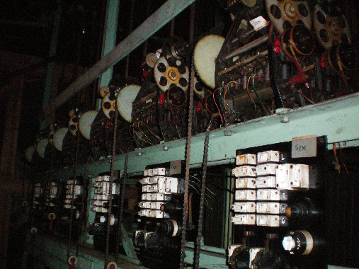
The image above shows part of the Harringay Julius Tote that is now in the London Science Museum's backup store at Wroughton. This system last operated at Harringay in 1987. The white porcelain fuse holders I mentioned, stand out brilliantly against the darkness, in the six fuse boards seen across the bottom of the image above. These are Horse Unit Fuse Boards and not Grand Total Unit Fuse Boards as they total the investments on individual runners and not the pool grand total. Remember, the Horse Units are almost the same as the Grand Total Units. The Fuse Boards have labels in the top right hand corner and the nearest one has the word SIX clearly visible on it. Five is just legible in the Fuse Board to the left, if the image is expanded. This identifies the nearest Fuse Board as belonging to the adder totalling the investments on runner number six. The five fuse boards to the left of this one relate to runner numbers one to five. Above each of the six Fuse Boards, are their associated Horse Units, or what were later called Shaft Adders. There is a tall rectangle drawn on the left hand side of the left hand drawing in the blueprint drawing below, which has the following two lines written below it Grand Total Fuse Board on top of View from back of board. There is a clear correlation between the Grand Total Fuse Board drawing in the blueprint image below and the Horse Unit Fuse Boards in the image above. I think this correlation would have been exact if we compared the specified drawings with systems of the same era. In the middle of the upper half of the Grand Total Fuse Board in the blueprint drawing below, there is a vertical column of horizontally oriented fuses labelled 1 to 6 with their associated values, which are identified by vertically oriented writing on their left hand side as Escapement Fuses. This corresponds to the central column of six white porcelain fuses in the Horse Unit Fuse Boards in the image above. To the right of this column of fuses in the blueprint drawing below are two more horizontally oriented fuses labelled 7 and 8 with their associated values, identified above by the horizontal underlined writing Escapement Fuses above 5 Amp. These are the two white porcelain fuses to the right of the column of six mentioned in the image above. On the left hand side of the column of six fuses in the Grand Total Fuse Board in the blueprint drawing below, there is a row of three vertically oriented fuses near the top of the associated rectangle, which has a second row of three vertically oriented fuses below. These are the left hand column of six porcelain fuses in the Fuse Boards in the image above.
Now something happens that needs a little explanation. So far all the comparisons have been made with the positions of the fuses in the Grand Total Fuse Board in the blueprint drawing below, directly relating to the general positions of the fuses in the Fuse Boards in the image above. Now however the text that appears below the name Grand Total Fuse Board in the blueprint drawing below, which is View from back of board, as mentioned in the previous paragraph, comes into play for some reason. Why this applies to the bottom of the drawing and not the top is only open to speculation. Perhaps it is because we are comparing images of Horse Unit Fuse Boards above with a drawing of a Grand Total Fuse Board below. Alternatively we could be seeing changes with time, however the drawing below has a creation date in 1934 and the first installation at Harringay took place in 1930 with an upgrade recorded in 1935 which is not a large time difference. A final thought is that for some reason the Julius Totes manufactured in the UK had minor differences to the ones manufactured in Australia, however I cannot imagine why that would be the case. Accepting that for whatever reason, what we see in the Grand Total Fuse Board in the blueprint drawing below, is now the View from back of board, we now have to transpose left and right as what is viewed on the left from the rear appears on the right from the front and vice versa. Below the central column of six fuses in the blueprint drawing below is an Alarm Relay consisting of a broken line leaning left of vertical representing the switch arm, and a medium sized broken circle below with the words Alarm above Relay inside, representing the activator of the relay, which has a second such relay on the right hand side. At the resolution of the image below it is difficult to recognise these words. Each of these two relays have an associated fuse seen on their right hand sides in the blueprint drawing below. These relays and fuses can be seen in the nearest fuse board in the image above one set below each of the two columns of six fuses. The Relays are dark and block part of the white from their associated porcelain fuses behind them. These fuses appear on the left hand side of the associated relays which is transposed from that in the blueprint drawing below where they are on the right, because we are looking at the front of the board in the image above as previously mentioned. The arms of the switches in the relays can be seen rising above the bodies of the relays in the image above. To the left of the Alarm Relays in the blueprint drawing below, there are two switches, the Motor Switch on the left and the Betting Circuit Switch on the right. In the nearest Fuse Board in the image above there are two circular switches seen one on top of the other on the bottom right hand side of the Fuse Board. Again in the image above these switches are on the right hand side of the board, whilst in the blueprint drawing below they are transposed on the left hand side. In the image above, the bottom switch has a white knob with a white band around the black body and the top one has an orange knob on top of a black body. Failing any concrete evidence one way or the other, I guess that the lower switch controls the motor. Finally, at the bottom of the second Fuse Board from the right in the image above, as the bottom of the first board is out of view, some of the pads in the three horizontal rows belonging to the connector can be seen with difficulty. They appear as well spaced faint copper coloured dots aligned in rows on the very dark background of the board. They are easier to see on a brighter screen and when the image is enlarged. This is the connector at the bottom of the Grand Total Fuse Board in the blueprint drawing below, where it is arranged as two parallel rows of 10 pads with a shorter row above these two with four pads. In the blueprint drawing below, the short row of pads is on the left hand end of the two ten pad rows. This is transposed in the image above as previously mentioned, where the short row of four is at the right hand end and actually extends further right than the right hand end of the two rows of ten pads and the row of four pads can be seen below the bottom switch in the second Fuse Board from the right in the image above. Part of the two rows of ten pads can also be seen in that Fuse Board above, at the bottom of the board passing below the two relays. Actually I think there are fewer pads in the two long rows in the image above, I can only identify six in each row. I think these Fuse Boards can accommodate different Horse Adding Units built with a larger number of escapements and even escapement shafts, to meet the requirements of larger installations. As can be seen in the blueprint drawing below, there are many pads in the two rows of 10 pads at the bottom of the Grand Total Fuse Board that seem to be spare as they show no connection.
 Go back to the index
Go to the bottom of the page
Go back to the index
Go to the bottom of the page
A group of six horizontal conductors can be seen below the bottom right hand corner of the Grand Total Fuse Board rectangle, on the left hand side of the blueprint drawing below. These plus two other conductors identified later, carry the Betting Circuits described in the Automatic Totalisators Limited Description of Electrical Circuit Diagrams document, which implement the primary function of the Julius Totalisator of recording the total value of transactions on each runner in a race per pool, as well as the grand total for each pool. This information is required to calculate the dividends for each race, which was done manually after reading the information from the Horse Units corresponding to the winning horse and the Grand Total Units, for each pool. These figures would then be applied to circular slide rules, which were manufactured to minimise the time taken to calculate dividends. The summation of transactions was performed mechanically, by the Escapement Shafts as the tickets were sold, which were activated by the solenoids shown in the blueprint drawing below. The six conductors mentioned, originate from inside the Grand Total Fuse Board rectangle. Near the point that these conductors descend out of the bottom of the rectangle and turn right, there is a label across them reading Escapement Terminals. This name refers to the fact that these conductors carry the pulses that activate the solenoids, shown in the Grand Total Fuse Board in the blueprint drawing below, that allow their respective Escapement Wheels to rotate a tooth for each activation. Inside the rectangle they attach to a representation of a connector previously described, and are labelled 3, 2, 1, in the top row and 6, 5, 4, in the bottom row. Outside the rectangle, the conductors travel right and then rise vertically along the left hand side of a second taller rectangle, which has the following two lines written below it Grand Total Unit on top of View from back. The group of six conductors rise on the left side of the Grand Total Unit or Adder, and three of the conductors peel off to the right and the other three continue up and eventually turn right, all six entering the Grand Total Unit rectangle. Each conductor in both groups of three, connects to one side of respective devices represented by pairs of medium sized circles grouped in two rows of three. Between these two rows is the label Bottom Escapement Shaft. These mentioned devices are the pairs of electromagnets that make up the escapement solenoids. These solenoids are activated by pulses from the TIMs (Ticket Issuing Machines) that are sequenced by the distributors, which in turn activate the escapement mechanisms, which allow the escapement wheels to rotate one tooth at a time, thus recording a bet for each activation. The escapement shaft, mentioned in the blueprint drawing below in the label Bottom Escapement Shaft, is a shaft that has the escapement wheels mounted on it, as well as the epicyclic gears that perform the adding functions. This Grand Total Unit shown to the left of centre in the blueprint drawing below, is what is called a Two Shaft Adder, as it has two escapement shafts or what were later called adding shafts. These six solenoids trip six escapements, as and when required by the TIMs and Distributors, on what is called the Bottom Escapement Shaft. Another two solenoids can be seen in the drawing below, above the Bottom Escapement Shaft. These two solenoids have the label Top Escapement Shaft to the right of them. These escapement shafts are mentioned throughout the 1935 Electrical Circuit Diagrams document. Like the six conductors that came from the connector above the Escapement Terminals label at the bottom of the Grand Total Fuse Board for the Bottom Escapement Shaft, the two conductors for the Top Escapement Shaft come from the same connector, pads labelled 7 and 8, which are the two right hand pads in the top row of ten in the connector. Each solenoid is labelled with a number and a value. The top solenoid is labelled 7 with a value of 1£ beneath and the one below is 8 with 5£ beneath. The next row of solenoids are labelled 5 1£, 3 10/- and 1 10/- and the bottom row 6 10/-, 4 10/- and 2 10/-. The escapement wheels can have differing numbers of teeth in them, the fewer the teeth in an escapement wheel the larger the bet recorded on each activation of the wheel. This completes the description of the group of six conductors that traverse between the Grand Total Fuse Board and the Grand Total Unit via the lower route in the drawing below. The continuation of the circuits provided by the six conductors just described, from the opposite side of each of the respective Escapement Solenoids back to the Grand Total Fuse Board, via the upper path in the blueprint drawing below, is described in the first paragraph below the blueprint drawing below.
The large circular device with a smaller concentric circle inside seen below these escapement shafts, at the bottom of the Grand Total Unit rectangle on the left side of the centre of the blueprint drawing below is a motor. The inner concentric circle has two tangential arms on its perimeter that represent the brushes and the top brush can be seen connected to a coil like winding also inside the motor's outer circle. The two conductors attached to the motor, travel down the drawing exiting the Grand Total Unit rectangle bottom centre, then turn left and extend to the left hand edge of the drawing where they turn upwards to the upper half left hand side of the Grand Total Fuse Board, where they turn right to enter the Fuse Board and each conductor connects to a pad. Each pad is connected to the top end of a fuse. The top fuse has a - sign on the left hand side of it and the bottom fuse a + sign. The bottom end of both fuses have pads with respective conductors connected to each pad, that travel down inside the left hand side of the Grand Total Fuse Board rectangle and connect to the right hand pair of pads in a group of four pads arranged in the shape of a square with the word Motor above the word Switch, located inside the square. I have never seen switches represented as they are in these old drawings and the following description of this switch is consistent with other switches in similar drawings of this equipment. This is a double pole switch. The upper two pads are one pole with a broken line between them showing the switch arm in the closed position. The switches in drawings I am accustomed to, have an unbroken line showing the switch arm, one end connected to the middle of its contact pad indicating the pivot end of the arm and the other end, if the switch is shown in the closed position as in this example, sits on top of its associated contact pad indicating the moving end of the switch arm. In this example, this upper pole carries the + motor supply voltage and the lower pole with its two bottom contact pads, again with the switch arm represented by a broken line, in the Motor Switch shown in the blueprint drawing below, carries the - connection. This type of switch is called a Double Pole Single Throw switch. The conductors then travel from the left hand pair of pads of the switch down the drawing and connect to the - and + pads, which are the first two pads in the short row of pads, at the top of the connector at the bottom of the Grand Total Fuse Board rectangle. The motor has a label on its right hand side that reads 1/50th H.P. with the word Motor below. The motor provides energy for motivating the escapement shafts via springs and clutches for each escapement shaft. The clutches disengage when their respective springs are fully wound.
The two pairs of vertical objects drawn on the left hand side of each of the escapement shafts, in the Grand Total Unit rectangle on the left hand side of the centre of the blueprint drawing below, which look like old fashioned fountain pens with their caps on, are Escapement Alarm Slip Rings labelled Escapement on top of Alarm Slip and below that Rings. These are mentioned in another extract from Automatic Totalisators Limited Description of Electrical Circuit Diagrams under the heading ESCAPEMENT ALARM & STARTERS LAMPS/ CIRCUITS, which is the fourth heading under the image below titled Bob Moran's Tote adder 10 register schematic. The right hand slip rings in each pair connect to one of two Alarm Relays, previously identified and shown near the bottom of the Grand Total Fuse Board rectangle, near the left hand side of the blueprint drawing below. These Alarm Relays are used to indicate that the associated escapement shaft spring has unwound, meaning the associated shaft has ceased recording bets, a fault condition requiring attention. The left hand slip rings in each pair are electrically connected by the vertical conductor drawn between them, which descends further exiting the Grand Total Unit rectangle, turning left for some distance and then rising to enter the Grand Total Fuse Board rectangle and connecting to the Escapement Alarm Terminal in the plug labelled Escapement Terminals. As previously mentioned, these alarm relays in the Grand Total Fuse Board rectangle below are represented by two small circular broken lines with the words Alarm with Relay below, inside each of them which are the actuators of the relays. There are two windings drawn for each Alarm Relay. The first extends horizontally left from each of the broken circles and both connect to the bottom of respective vertically oriented fuses on the right hand side, via conductors that pass under each broken circle. The windings seen rising at 45 degrees to the left of the broken circles is attached to their respective right hand Escapement Alarm Slip Rings as already described in the opposite direction. Above each of the Alarm Relay broken circles a long broken line can be seen rising from a contact pad at about ten degrees to the left and reaches a position to the left of another contact pad. These long dotted lines represent the switch arms of the relays. When either relay is activated this arm moves left and contacts the more distant contact pad to the left of the arm. It can be seen by following the conductor that joins these two left contact pads of each Alarm Relay together, that if either Alarm Relay activates, the large lamp visible near the top left corner of the image below is illuminated. This lamp has the following four line annotation Signal Lamp at above the line top of frame above the line Red Lamp above (Escapement Alarm), which put together reads: Signal Lamp at top of frame Red Lamp (Escapement Alarm). These red lamps are mentioned in the Circuit Diagrams document under the subheading Escapement Cutout and Alarm Circuit, below the heading ESCAPEMENT ALARM & STARTERS LAMPS/ CIRCUITS, many paragraphs below and relates to the Horse Units as well as the Grand Total Units. There is an image of a Horse Unit below titled A Two Shaft Electro Mechanical Shaft Adder, which later became known as a Shaft Adder, in which an Escapement Shaft can be seen, which later became known as an Adding Shaft and a pair of Escapement Alarm Slip Rings can also be seen, and are referred to in multiple paragraphs below that image and described in the second paragraph above the following image titled Bob Moran's Tote adder 10 register schematic. The Escapement Alarm Signal Lamps, which are at the top of the frame as mentioned in the text from the blueprint drawing below Signal Lamp at top of frame, are inside the bottom half of each of the white boxes above each adder window in the image above titled Part of a Julius Tote Mainframe, and each window in that image contains a Horse Adding Unit like the Grand Total Unit shown in the blueprint drawing below.
Julius Poole and Gibson blueprint
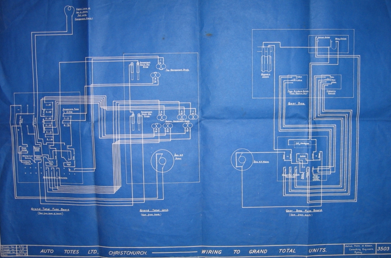
This is the completion of the description of the circuit that connects the escapement solenoids in the Grand Total Unit to the Grand Total Fuse Board seen in the blueprint drawing above, which began in the third paragraph above the blueprint drawing above. As the name Grand Total Fuse Board implies, the rectangle bearing this label seen near the left hand edge of the blueprint drawing above, contains amongst other things, fuses. The largest group of fuses can be seen in two columns. The first column is central in the upper half of the rectangle labelled Grand Total Fuse Board and is associated with the group of six conductors entering this rectangle horizontally, just below the top right corner of the rectangle. The second column consists of only two fuses with their associated conductors seen below the group of six horizontal conductors inside the Grand Total Fuse Board rectangle, which turn upwards and cross the group of six conductors to the right of the Grand Total Fuse Board rectangle. As already described, the lower group of six conductors are each connected to one side of their respective escapement mechanism solenoids, labelled Bottom Escapement Shaft in the blueprint drawing above, inside the rectangle labelled Grand Total Unit, to the right of the Grand Total Fuse Board rectangle. These six circuits continue from the opposite side of each respective escapement mechanism solenoid back to the Grand Total Fuse Board. Starting at the opposite end of these connecting conductors carrying these six circuits, inside the Grand Total Fuse Board rectangle, these six conductors are respectively connected to six contact pads on the left hand side of the column of six fuses. To the right of this column of contact pads are the fuses, which respectively connect to a corresponding second column of six contact pads, which are all shown connected together by a vertical conductor. The fuses are shown in the diagram as two dotted lines that cross each other at a very small angle, such that the one dotted line connects the top of the left hand contact pad to the bottom of the right hand contact pad and the second line connects the bottom of the left hand contact pad to the top of the right hand contact pad. This is not clear in the resolution of the image above, however the dotted nature of the lines is visible. These fuses have labels beneath them starting at the top with 1 - 10/- then 2 - 10/- below then 3 - 10/- then 4 - 10/- followed with 5 - 1£ and finally 6 - 10/-. The second column of fuses to the right consisting of two fuses for the Top Escapement Shaft are labelled 7 - 1£ and 8 - 5£. It is not possible to discern much of the text at the resolution of the image above but it is possible to follow the layout of the drawing. The left hand column of six fuses has the following text oriented 90 degrees anticlockwise so it stands vertically on the left side, and reads Escapement Fuse followed by - 5 Amp. The right hand column of two fuses has the text across the top Escapement Fuses with 5 Amp below.
The gearbox drawn in the right hand half of the blueprint drawing above, is used to extract the commission from the pool grand total to arrive at the net pool total for the calculation of odds. There is a box in the lower part of the Gearbox drawing, bottom right in the blueprint drawing above, which is labelled Gear Box Fuse Board with the line View from back below. Above this is a rectangle labelled Gear Box. At the bottom of this Gear Box rectangle two switches are drawn, each inside a smaller rectangle.
The left switch is labelled Place Dividend Switch, which has two settings labelled 2 Divs and 3 Divs, with the line Place Machine Only below the line Place Dividend Switch below the left hand smaller rectangle. This is used by the chief mechanic in the Machine Room, to respond to the request from the Tote Manager at the Race Day Control Console (RDC) in the Control Room, for a 2 dividend or 3 dividend place pool configuration, confirming that the system has been configured for either a two dividend or three dividend place pool. The means of signalling this communication between the machine room and the control room is via signal lights as can be seen in the drawing at the top of this page. It can be seen in the connector at the bottom of the Gear Box Fuse Board in the image above that the 3 Div position of the switch, connects the right hand two vertically separated pads of the connector together and the pair of pads to the left of these are connected through the switch when it is in the 2 Div position. Below these two pairs of contacts in the connector are the words Place on top of Dividend on top of Switch on top of Terminals. Now looking at the same connector in the drawing at the top of this page, which is in the box which has the name Gear Box inside, to the right of the middle of the bottom row of boxes, with the underlined text Gear Box Fuse Board underneath it. When the discontinuity squiggly line side of the box is on the bottom, instead of the top as in the top row of boxes in the image at the top of this page, it means this box is upside down. Consequently, the connector inside the box is shown at the top of the Fuse Box in the blueprint drawing at the top of this page and at the bottom in the blueprint drawing immediately above. Additionally as mentioned in the previous paragraph, the Gear Box Fuse Board label in the image above, has the line View from back below it. Consequently, as the Gear Box Fuse Board shown in the image at the top of this page is a front view, the four pads which were on the right hand side of the connector shown in the drawing above, are now on the left hand side in the drawing at the top of this page. This means that the 3 Div position of the Place Dividend Switch connects the leftmost pair of vertically separated contact pads together in this orientation of the connector and the 2 Div position of the switch connects the pair of pads to the right of these first pads together. Looking at the 3 Div position first bridging the leftmost vertical pair of pads of the connector in the lower Gear Box box in the image at the top of this page, it can be seen that the upper pad of this pair of pads has a conductor rising vertically and exiting the top of the box, then crossing a group of three horizontal conductors, then a single conductor and finally the bus of eight conductors at right angles, terminating in a + sign with the vertically oriented word Three on top of it. The lower pad of the first vertical pair of pads, exits the box on the left hand side and then rises vertically between the Grand Total and Gear Box box, crossing the same multitude of horizontal conductors and also terminating in a + sign with the vertically oriented word Three on top of it. The pair of pads to the right of this first pair on the left of the connector at the top of the Gear Box Fuse Board in the blueprint drawing at the top of this page, corresponding to the 2 Div position of the Place Dividend Switch and have conductors attached to them. These follow similar paths to the first pair ending up in respective positions with + signs directly to the right of the previously described + signs, only above these two latest described + signs, are the two vertically oriented words Two. We now have the four vertically oriented words three two three two respectively sitting above the four + signs. Both of the three two pairs have up pointing brackets above them. The left bracket points upwards to two lines of vertical text To Place Dividend Lamps (Right Hand Set) on the left with Machine Room Signal Board on the right. The right bracket points upwards to two lines of vertical text To Place Dividend Lamps (Right Hand Set) on the left with On Control Room Switchboard on the right. Now we have the means of communication mentioned. We now know there is a pair of lights signifying 3 Div and 2 Div in both the Machine Room Signal Board and the Control Room Switchboard and they are both labelled Right Hand Set. There is another pair of similar lights called 3 Div and 2 Div that belong to the Left Hand Set. Instead of being controlled by the Place Dividend Switch in the Gear Box in the Machine Room it has another similar switch located in the Control Room. This switch controls the Left Hand Set lights. So the Tote Manager in the Control room used to set his 2 Div/3 Div switch to the selection required for the race. This accordingly lit either the 2 Div or the 3 Div light depending on the switch position, in the Left Hand Set, which the manager could see in the Control Room and the mechanic/engineer could also see in the Machine Room. The mechanic/engineer in the Machine Room would then make the adjustments to comply with this request and then set his Place Dividend Switch illuminating the right hand 2 Div or 3 Div light, to confirm the requested setting from the Control Room. Now these sets of lights should line up in both indicators in the Machine Room and the Control Room and either indicate 2 Div, 2 Div or 3 Div, 3 Div. Any other indication is a no-go condition. This two dividend or three dividend configuration requires the selection of the correct gear ratios for the odds calculation system.
The switch to the right of the Place Dividend Switch in the upper right quadrant of the blueprint drawing above, is labelled Capacity Switch, which has three settings. Each setting has a pair of contacts, the first horizontally separated and the other two deviating somewhat from horizontal, aligned in a column inside the Capacity Switch rectangle, which is bottom right in the Gear Box rectangle. The top pair of contacts are labelled Min , the middle Mean and the lowest Max. These settings relate to the expected turnover of the race, which requires the odds calculation system to be configured accordingly. The settings are described in the 1935 Electrical Circuit Diagrams document below, under the heading CAPACITY SIGNAL CIRCUIT./ Drawing NO. 3487. The stubby cylindrical looking object, drawn with two slip rings and two brush arms in contact with the slip rings, on the left hand side of the box labelled Gear Box, in the top right quadrant of the blueprint drawing above, is labelled Magnetic Clutch. This clutch allows the constant drive from the drive motor, shown below and to the left of the clutch, outside the left hand side of the Gear Box Fuse Board rectangle, to be electrically controlled engaging the drive when required and disengaging it when not.
This drive motor shown outside the left hand side of the Gear Box Fuse Board rectangle in the lower right quadrant of the blueprint drawing above, has connections to the tops of two fuses located on the left and right hand sides inside the Gear Box Fuse Board rectangle, at mid height level. Both these fuses have the vertically oriented word Motor appropriately standing on their left hand sides, which is not legible at the resolution of the image above. From the pad at the bottom of the right hand fuse a conductor travels left and joins the right hand lower pad of another Double Pole Single Throw switch, which looks a lot like a square. From the pad at the bottom of the left hand fuse a conductor travels right and joins the bottom of another fuse and after a short descent turns right again passing underneath the body of the switch and rises to join the right hand upper pad of the switch. As previously described, this switch is also shown in the closed position by the dotted lines from the two right hand pads to the two left hand pads of the switch. The switch has the simple label inside it Switch, which is the On-Switch. From the two left hand pads conductors travel down, the left conductor of the pair joining the bottom of a vertical pair of pads, which has a - sign to the right of it and the right hand conductor joins the upper of the pair of pads, which has a + sign next to it. These - and + pads belong to the connector lying along the base of the Gear Box Fuse Board box. Two lines of underlined vertically oriented text lie below the + and - pads in the connector, which read Supply on the left hand side of Terminals. There is a label to the right of the motor which reads 1/20th H.P. Motor. I have not described this motor drawing as I have already done that for the motor seen to the left of this one in the drawing above. It is interesting to note however, that this motor on the right has its coil like winding connected to both brushes, whilst the motor on the left has its connected to the top brush only. The left hand motor is in a series motor winding configuration and the right hand one is a shunt motor winding. These different winding configurations determine the speed torque and power for the motor application.
The two shaft adder shown in the image below, is a close match to the one shown in the Grand Total Unit rectangle shown left of centre in the blueprint drawing above. Technically, the adder shown below is a Horse Adder, which is an adder for totalling the sales on a single runner, whilst the one in the blueprint above is a GT Adder, used for calculating the Grand Total of all Horse Adders in a particular Pool. In this version of the Julius Tote however, I have been told that the Horse Adder and the GT Adder were interchangeable. Another difference, is that the Adder in the blueprint drawing above has its own motor, whilst the one shown below has a drive pulley, located at the rear left corner near the top, which is not in view, which connects to an external drive shaft in the mainframe containing it, that drove all the adders associated with a single pool. All the adders of the type shown below, belonging to the same pool connected to the same drive shaft via a belt.
In the image below, three solenoids can be seen across the bottom of the adder each containing a pair of coils. These three solenoids trip escapement mechanisms that allow escapement wheels to advance one tooth for each activation, which is the method of recording bets. Above the solenoids is a substantial horizontal rod which contributes to holding the left and right mounting plates of the adder together. To the rear and slightly above this support rod an Adding Shaft (or escapement shaft as referred to in the old document extracts) can be seen, which is parallel to the rod. This Adding Shaft has six Escapement Wheels mounted on it, five of which are clearly visible as they are of greater diameter than the other cogs on the shaft. The three solenoids mentioned trip the escapement mechanisms of three of these escapement wheels. At the same height of the three solenoids but on the other side of the adding shaft are another three solenoids which trip the other three escapement mechanisms for the remaining three escapement wheels on the adding shaft mentioned. In the Grand Total Unit, inside the tall rectangle to the left of centre in the blueprint above, at mid height level the pairs of coils in the solenoids can be seen. The three solenoids in the bottom row in the blueprint above, are the ones visible in the image below and the upper three solenoids in the blueprint are the ones mentioned on the opposite side of the adding shaft in the image below. Above the adding shaft in the image below there is another horizontal shaft with two large cog wheels on it which are inside the two mounting plates and another large cog on the right hand side of the shaft which is outside the right hand mounting plate and a smaller cog on the same shaft, outside the left hand end plate. Behind this shaft is a second adding shaft with an extra four solenoids, however this second adding shaft shown in the blueprint above, only has two additional solenoids shown at the top of the Grand Total Unit rectangle. The number of adding shafts as well as the number of solenoids with their associated escapement mechanisms per adding shaft, per adder was configurable depending on the requirements of the system. The more escapement mechanisms per adding shaft and the more adding shafts per adder, the more ticket issuing machines the system was capable of supporting. This second adding shaft is not visible in the image below. The coils of the near side solenoids in the second adding shaft can be seen however, above and behind the first adding shaft in the image below.
A Two Shaft Electro Mechanical Shaft Adder
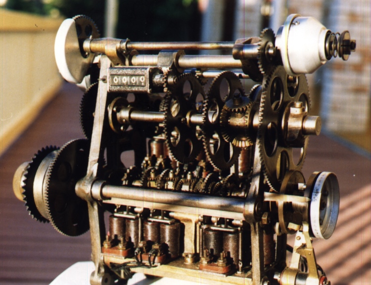
At the top right hand end of the adder shown above, a shiny cone like aluminium cover can be seen. Inside the left hand end of the conical cover, there is a mechanical clutch. This clutch prevents the constant drive from the drive shaft motor, from winding the spring in the visible adding shaft any further when it is fully wound. This is one of the clutches mentioned at the end of the second paragraph above the blueprint drawing above labelled Julius Poole and Gibson blueprint. Protruding from the right hand end of the cover a spring can be seen. This spring is the clutch spring, which holds the clutch plates together and controls the amount of friction between the plates. The tension of this spring is adjustable with the nut seen on the right hand end of the shaft. The conical cover keeps dust and grime out of the clutch. There is a second one of these clutches for the rear adding shaft, which is not in clear view of the front image of the adder above, however there is evidence of it. To the left of the conical cover in view, there is a shaft that travels width wise across the top of the adder. Below this shaft is another parallel but much larger shaft and below that another shaft like the one at the top of the adder. This lower shaft, serves the same purpose as the one at the top of the adder, only for the rear adding shaft. This lower shaft is oriented the opposite way around to the shaft at the top, with the clutch and conical cover at the left hand end of it. Looking closely at the image above, below and behind the sprocket and its aluminium guard on the left hand end of the top shaft, a small section of the bottom of the rear conical cover can be seen.
Above the substantial horizontal rod above the row of solenoids at the bottom of the adder above, the front adding shaft can be seen as identified in the paragraph above the image. As previously mentioned, Adding Shaft is the later name for what is called Escapement Shaft in the extracts from the old document, probably due to the fact that this shaft does not only have escapements on it, but also contains epicyclic gear trains that perform the adding function, which is the purpose of the Adder. This adding shaft extends to the right past the right hand support plate of the adder to two copper coloured Slip Rings and at the far right hand end a graduated aluminium drum. There is a pointer seen anchored on the outside of the right hand support plate pointing right and extending to the graduations of the aluminium drum. The slip rings and aluminium drum are located below the conical cover mentioned in the previous paragraph. On the shaft between the two slip rings there is another spring. This spring provides the energy to rotate the front adding shaft of the adder, as the right hand slip ring is attached to an extension of that adding shaft. This spring is described in the second and third paragraphs below the subheading Escapement Cutout and Alarm Circuit of the company document extract below titled ESCAPEMENT ALARM & STARTERS LAMPS/ CIRCUITS / Drawing NO. 3486. There is another group, consisting of the slip rings, the spring between them and the graduated aluminium drum, which is not in view, hidden behind the large cog on the right hand side of the shaft adder shown above, which performs the same function as the group in view, only for the rear adding shaft. The springs that energise the adding shafts can easily be seen in Bob Moran's schematic below titled Bob Moran's Tote adder 10 register schematic. At the bottom right corner of the schematic, the two slip rings can be seen, identified by the label Slip Ring Contacts, with the spring in question between them. This is for the front adding shaft that is visible in the image above and the one for the rear adding shaft can be seen as well in Bob's schematic below, in the upper half of the image and to the left of the lower one. Bob has labelled these springs Spring Accumulator, at the end of arrows pointing to the springs. The rear adding shaft that is not visible in the image above, can be seen in Bob's drawing below, to the left of the rear slip rings and spring. The graduated aluminium drum that I referred to in this paragraph, Bob has called a Graduated Dial Drum in his schematic below.
Attached to the rear clutch and its associated conical cover, as clearly seen on the left hand side slightly above mid height level, of Bob's schematic below and also described at the end of the paragraph before last, is the main drive pulley. This is labelled INPUT MAIN DRIVE PULLEY in Bob's schematic below, which is connected to the main drive shaft for all the adders in a single pool in the Julius Tote mainframe by a belt. Attached to the right hand side of the pulley, as seen in Bob's schematic, is a cog with the label 48T, standing for 48 Teeth and below that CW rotation for Clockwise rotation. This cog engages another cog seen located above the first in Bob's schematic, which is also labelled 48T and has ACW for Anticlockwise written above the cog's spindle. This cog wheel can be seen top left in the two shaft adder shown above, which has an aluminium guard covering the front section of it. This second cog then drives the shaft seen across the top of the adder shown above and drives the clutch inside the shiny aluminium conical cover seen top right of the adder above. This is clearly seen in Bob's schematic below, by following the broken line from the spindle of the ACW marked cog, right then up and right again extending to the right hand top corner of the schematic, to drive the clutch for the front adding shaft. This is the means of driving the two clutches in the Adder from the same drive pulley. The output of the right hand clutch then drives a small cog, seen protruding out from the front of the adder, immediately to the left of and in front of the shiny conical clutch cover, which drives the largest cog in the adder, seen on the far right hand side on the outside of the right hand mounting plate of the adder in the image above. Following this in Bob's schematic below, on the left side of the clutch in the top right corner there is a small cog with dark shading like the rest of the left hand side of this clutch, with the characters 14T below the spindle. This 14 Tooth cog meshes with another cog below identified as having 30 teeth 30T in Bob's schematic below, which was identified in the image above as protruding out from the front of the adder. This 30 tooth cog in turn drives the largest cog in the adder seen below it, identified as having 100 teeth, labelled 100T in Bob's schematic below. The 100T cog together with the 30T cog connect the clutch in the top right corner, to the slip rings and drum in the bottom right corner, of Bob's schematic below. The bottom of this large cog now drives a small cog mounted on an extension of the front adding shaft on the right hand side of the right hand mounting plate. This small cog is connected to the left hand side of the left hand slip ring disk, which hides the small cog from view in the image above. The small cog and the left hand slip ring disk rotate together independently of the rotation of the adding shaft they are mounted on. This can be seen in the bottom right corner of Bob's schematic below, where the bottom of the grey shaded large 100T cog engages a small 16T cog fixed to the left slip ring disk, which is also shaded grey. This gear train just followed all the way from the Main Drive Pulley, winds the spring, that is located between the two slip rings, up and this spring provides the energy for rotating the escapement wheels and epicyclic gears on the front adding shaft. This spring is clearly visible in the schematic below, between the two slip ring disks labelled Spring Accumulator. Note in Bob's schematic below that the right hand slip ring disk is a lighter shade of grey to the left hand slip ring disk, indicating that these two assemblies are not fixed to each other. With no betting activity, the right hand slip ring disk that is fixed to the output of the front adding shaft, will not rotate as none of the escapement mechanisms in the adding shaft are being activated. This left hand slip ring rotates, driven by the gear train we have followed, until a stop peg on the left hand slip ring engages a second stop peg on the right hand slip ring stopping the left hand slip ring from rotating further, which causes the clutch in the drive train to break friction and slip. The stop pegs are mentioned in the second paragraph below the subheading Escapement Cutout and Alarm Circuit of the company document extract below titled ESCAPEMENT ALARM & STARTERS LAMPS/ CIRCUITS / Drawing NO. 3486. They can also be seen in the bottom right corner of Bob's schematic below, between the two pairs of slip rings above the spring, shown engaged with each other which is their normal resting position, labelled Driving Studs shown rotated 90°. With betting activity the escapement wheels, or what are called INDEX WHEELS in Bob's schematic, rotate, with the epicyclic gears summing the rotations towards the centre of the adding shaft, where the left and right shaft segment totals are summed by another epicyclic gear and passed through the shaft to the right hand slip ring disk, where its rotation corresponds to the sum total of the rotation of each individual escapement wheel. In other words, the angular displacement of the right hand slip ring disk equals the sum of the angular displacement of all of the escapement wheels on the adding shaft. As the right hand slip ring disk's associated stop peg has advanced, the stop peg on the left hand slip ring is now free to allow the left hand slip ring to rotate again and the clutch no longer slips and the left hand slip ring follows the right hand slip ring. This means the whole gear train is moving again, now recording bets. This largest of the cog wheels seen on the right hand side of the adder in the image above, is mounted on a shaft that looks like the same shaft that the other two large cog wheels to the left are mounted on, which are on the inside of the right hand mounting plate. We now come to an excellent example of the epicyclic gears that exist in the adding shafts, as this largest cog wheel on the outside of the right hand mounting plate is connected to the right hand bevel gear of a large epicyclic gear arrangement on the inside of this mounting plate, which is clearly visible in the Adder image above and is easier to see than the epicyclic gears in the adding shafts.
This large epicyclic gear arrangement, consists of two pairs of bevel gears where the axis of one pair is at right angles to the axis of the other pair, as seen in the Adder image above. The function of this epicyclic gear arrangement, involves the three largest cogwheels in the adder. It adds the rotation of the large cog on its right hand side, representing the total of the front adding shaft, to the rotation of the not quite so large cog on its left hand side, representing the total from the rear adding shaft and imparts that summed rotation to the second large cog on its left hand side, representing the final sum of the Adder, which is transmitted to the counter clearly visible top left on the Adder shown above, via a small cog on the right hand side of the counter. As a direct consequence of the bold text in the last sentence, an essential property of the adding shafts is revealed. That is, some cogs are fixed to the shafts they are mounted on and they both rotate together and other cogs are not fixed to the shafts they are mounted on and both rotate independently. In the Adding Shafts, the shaft total epicyclic gear in the centre of the shaft, transmits its rotation to the next stage of the equipment through the shaft that the escapement wheels and their associated epicyclic gears are mounted on, without interfering with the independent rotation of those escapements and gears mounted on it. In the case of our example of the large single epicyclic gear in the adder image above, the rotation of the vertical axis epicyclic gears around the horizontal shaft, is transmitted by the horizontal shaft that the vertical shaft is fixed to, through the large cog on its left, which is mounted on but not fixed to the horizontal shaft, to the second large cog on the left. This can clearly be seen in Bob Moran's schematic below titled Bob Moran's Tote adder 10 register schematic. To the right of centre of that schematic the four bevel gears of the large epicyclic gear arrangement can be seen looking like a tall oblong thick lined rectangle with chamfered corners with the label Differential "A" on the right hand side of it. There is a broken vertical line joining the upper and lower bevel gears, which is the axis of rotation for those bevel gears. This vertical axis is not actually fixed in the vertical position and is free to rotate in a vertical plane, extending into and out of the drawing, around the horizontal axis, always in the same direction. In Cartesian geometry, the plane I call the Vertical Plane is the one in which the Y and Z axes exist. I will continue to use the name vertical axis rather than vertical plane for ease of reference to the schematic below and the image of the adder above. It is the rotation of the vertical axis around the horizontal axis of this epicyclic gear arrangement that is the sum of the rotation of the large cog to the right of the epicyclic gear with that of the rotation of the large cog to the left of it. It does not matter if the left hand large cog, which is connected to the left hand bevel gear of the epicyclic gear, causes the vertical axle to rotate around the horizontal axis, or if the right hand cog connected to the right hand bevel gear causes the rotation and if both are rotating, the vertical axle just rotates faster and consequently further. The vertical broken line mentioned, representing the vertical axis of the epicyclic gear in Bob's schematic below crosses the right hand end of a horizontal broken line seen travelling left from a little circle, which is on a T intersection. This little circle identifies a connection between the vertical broken line or vertical axis or axle and the horizontal broken line or final sum shaft of the adder. This horizontal broken line in Bob's schematic then passes through the left hand large cog wheel without a connection to it, meaning the axle passes through the cog without affecting the independent rotation of the cog and connects to the two cog wheels further left, where the little circles on the broken line specify connections to those cogs. The right hand cog wheel of the two cog wheels mentioned on the left, in Bob's schematic below, is identified as a 70T cog, which drives a 40T cog below it, which in turn provides the input to the counter that looks like a wide oblong rectangle in the schematic below, with the words UNIT COUNTER on top of FOUR DIGIT 9,999 inside it. This counter is clearly visible top left in the Adder in the image above seen in its reset state displaying 0000. The left hand cog in this final sum shaft, shown in Bob's schematic below is a 66T cog, which drives a 99T cog below it, which in turn drives a sprocket on its left which provides the input to the odds calculating system via a chain on the sprocket.
The left hand large cog in the group of three large cogs, seen in the two shaft adder image above titled A Two Shaft Electro Mechanical Shaft Adder, is the rear adding shaft counterpart to the large cog on the right, which is for the front adding shaft. Both these cogs are downstream of their respective clutches, which wind up their respective adding shaft springs through their left hand slip ring disks, until they catch up with the right hand slip ring disks that represent the instantaneous betting totals for their respective adding shafts. At the top right section of the left large cog there is a small cog on the shaft behind it which drives the large cog. The shaft this small cog is on, is the rear adding shaft drive gear train counterpart, to the shaft across the top of the adder in the front adding shaft drive gear train. To the left of this small cog on the lower shaft on the outside of the left hand mounting plate, hidden behind the top left cog with the aluminium guard cover is the clutch and its conical cover associated with the rear adding shaft as previously identified.
Finally, on the subject of the adder in the image above titled A Two Shaft Electro Mechanical Shaft Adder, let's revisit the left and right slip rings seen low down at the far right hand side of the Adder in the image above, to the left of the graduated aluminium drum far right. These slip rings consist of two metallic and consequently conducting circular strips mounted on the perimeter of two insulating material disks which are mounted next to each other on a shaft. Apart from the two stop pegs mounted on the inside edge of both disks mentioned previously, there are a pair of electrical contacts one on each disk surface projecting out from each insulator towards the other disk. They are so arranged that when there is no betting activity, they are close to each other back to back, but not in contact with each other and are kept from getting any closer to each other via the shortest path, by the stop pegs. When betting activity takes place the right hand slip ring rotates, driven by the adding shaft which is energised by the spring between the slip rings, increasing the distance between these electrical contacts. Under normal operation the left hand slip ring now also rotates recording bets, rewinding the spring and chasing the right hand slip ring, no longer being restrained by the stop peg on the right slip ring which has advanced with its slip ring, driven by the clutch to return the contacts to their back to back but separated condition when the stop pegs engage again. This happens at the end of a burst of betting activity, when the right hand slip ring stops rotating along with the graduated aluminium drum attached to its right hand side. If for any reason the drive train through the clutch fails, then the left hand slip ring disk will not rotate to follow the right hand slip ring and the contacts will continue to separate until they are 180 degrees apart from each other and then start to close with each other again this time face to face. In this relative movement between the left and right rings the stop pegs do not engage again, but the two contacts eventually meet which effectively is the closing of a switch. The rest of this switch circuit involves the conductive slip rings. At the bottom edge of the adder image above near the right hand side, a fulcrum can be seen with two arms projecting upwards which are conductive. The right hand arm tip, makes contact with the near side of the rim of the right hand slip ring and the left hand arm makes contact with the far side rim of left hand slip ring. The tips of these arms are what are called brushes in the old company Description of Electrical Circuit Diagrams document, that bear on the slip rings. The electrical contacts that previously made contact representing the closing of a switch, are each connected electrically to their respective slip rings, so once the electrical contacts touched each other, the left slip ring arm was electrically connected to the right hand slip ring arm as the rims of the slip ring disks are conductive. The left and right hand arms have electrical wires attached to them that connect them to the Alarm Relay for the front adding shaft Escapement Alarm as described in the paragraph above the blueprint drawing above titled Julius Poole and Gibson blueprint. The electrical contacts mentioned on each slip ring disk, can be seen in Bob's schematic below. Looking at the pair of slip rings bottom right which are for the front adding shaft, these contacts are shown in their normal back to back position at the bottom end of each slip ring. There is a pointer pointing up to the right hand contact with the following text 37 Index to activate alarm 3.5 units counter Normally open electric contacts shown rotated 90° Contacts make at 355° ACW rotation signalling a drive fault. The slip rings for the rear adding shaft with their contacts visible above the shaft they are mounted on can be seen in the upper half of Bob's Schematic below, to the right of centre. There is another pointer pointing down to the left hand contact with similar text to that of the front adding shaft except that instead of 37 Index to activate alarm 3.5 units counter... it reads 37 Index to activate alarm 14.5 units counter.
Following is a diagram of the adder shown above. It looks like a diagram produced by a company documenting its engineering products, however it was produced by Bob Moran who is an engineer who had his own engineering company named Precision Dynamics. Bob has a passion for history and engineering. He studied the Julius Totes and the type of adder shown in the image above amongst others and created the drawing below, almost half a century after this machinery became redundant. When I start to think I am obsessional about this history, works like the drawing below, which to me is a beautiful piece of artwork which actually serves a purpose of succinctly describing a piece of equipment, remind me that I am just a beginner. Regarding my use of the word succinctly, this is blatantly evident when looking at the amount of text I have produced just trying to describe some of the details contained in this schematic drawing. Thank You Bob, for having produced this magnificent piece of work for such an altruistic purpose as helping to record a historically significant piece of machinery for those interested in the history of technology. As can be seen in the identification text in the bottom left corner of the schematic below that Bob completed this work on the Centenary of the commencement of operation of the first Julius Totalisator in 1913.
Bob Moran's Tote adder 10 register schematic
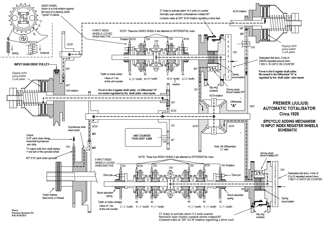
Now a recapitulation of the drive train I have already described, without the distraction of bouncing between the first two images above, referring only to the schematic above for continuity to do justice to Bob Moran's wonderful schematic drawing, as it is after-all a complete overview of this Julius Tote Shaft Adder. The drive pulley can be seen in Bob's drawing above near the left hand side, slightly above mid height level labelled INPUT MAIN DRIVE PULLEY. To the right of the top of the pulley is a broken line identifying the drive train mentioned. Attached to the right hand side of the pulley, as seen in Bob's schematic, is a cog labelled 48T and CW rotation, containing previously explained acronyms. This cog engages another cog seen located above the first in Bob's schematic, which is also labelled 48T and has ACW written above the cog's spindle. The broken line then travels right, then up and then over to the right hand side if the drawing via a broken continuity shaft in the schematic above, as identified by the jagged breaks on the joining ends of the shaft in between which the body of the shaft is not shown. Although the ends of this shaft do not align the continuity of the broken line identifies these two shaft stubs as being the same shaft. The broken line then enters the clutch assembly with its unmistakable cone like cover seen in the top right corner of the schematic above. The arrow head points up to the clutch plates. The lower part of the clutch plates are labelled bottom right of the clutch, Slipping Clutch on top of Spring loaded on top of 2 cork plates. The clutch then drives the dark grey shaded part of the clutch assembly which shows a small cog as part of this assembly labelled ACW rotation above the cog and 14T bottom left. The broken line drive path now passes through another cog labelled 30T top left and CW below the spindle on the right hand side. The bottom of this cog engages with the largest cog wheel in the adder labelled 100T on the right above the spindle. It took some time for me to fully grasp the function of this large cog. The problem was that it appears to have two functions. Although the two functions are integrally linked and do occur simultaneously, I think it aids comprehension like slowing the action down, by examining it as two separate functions. Firstly it is part of the winding mechanism for the spring located between the two slip rings for the front adding shaft seen in the bottom right corner of the schematic above. Secondly it is part of the drive train which transfers the output of the front adding shaft, recorded as angular displacement on the right hand slip ring with its attached graduated drum in the schematic above, to the right hand bevel gear of the final summing epicyclic gear, which is attached to the left hand side of the 100T cog. The first function of winding the adding shaft spring is fulfilled by following the remainder of the drive train we have followed. Picking up from the 100T cog, the broken line entering the cog at the top stops with a downward arrow, implying winding motion being applied to the 100T cog. The bottom of this large 100T cog drives a small cog labelled 16T on its left hand side below the shaft it is mounted on. This cog has the left hand slip ring attached to its right side as indicated by the dark grey shading permeating through both devices. The broken line descending through the bottom of the 100T cog and the 16T cog, now turns right into the LH (Left Hand) slip ring then turns up the slip ring. This is the end of the drive train for the winding function as the subsequent rotation produced in the left hand slip ring, starts winding up the spring between the left and right slip rings, whether the right hand slip ring is stationary or recording bets, the only difference being the rate of winding up. The adding shafts escapement wheels and epicyclic gears are made as small and light as possible making these shafts quick to respond to bet traffic in comparison to the rest of the adder's more inertia limited parts. This means at the start of a betting burst the right hand slip ring, activated by the adding shaft, races ahead of the left hand slip ring with its heavier winding equipment and output devices. When the left hand slip ring's attached equipment overcomes its inertia and the rate of bet traffic increase levels off, it stops falling behind and eventually starts catching up. This winding continues until the stop pegs, or what Bob calls Driving studs engage marking the fully wound condition of the spring. This stops the winding motion as the right hand slip ring is locked stationary, causing the independent left hand slip ring to also come to a halt, causing the clutch to break friction and slip. The independent rotation of the left and right slip rings, is identified in Bob's schematic by the different shades of grey for the two slip rings as previously mentioned. The second function of the large 100T cog, of transferring the output of the front adding shaft to the right hand bevel gear of the final summing epicyclic gear, can be followed by tracing the broken line from the centre of the front adding shaft. The front adding shaft can be seen across the bottom of Bob's schematic above and the broken line begins in the centre of the shaft at the shaft total epicyclic gear of the adding shaft. This shaft total epicyclic gear, adds the sum total of the individual rotation of all the escapement wheels on the left hand side of it, to the sum total of all the escapement wheels on the right hand side. As previously described the output of the adding shaft is recorded as the total angular displacement of the vertical axle with its bevel gears of this shaft total epicyclic gear, around the horizontal axis in the Cartesian YZ axes plane and the connection of the vertical axle to the horizontal adding shaft is identified by the small circle at the junction of the two at the T intersection of the vertical and horizontal broken lines. The horizontal broken line now follows the adding shaft right to join the right hand slip ring and its associated graduated drum, the connection to the right hand slip ring again being identified in the drawing above by the little circle at the junction with the shaft. The broken line then rises inside the RH slip ring, then turns left and passes through the stop pegs labelled Driving studs in Bob's schematic above. It then travels down the LH slip ring and turns left into the previously identified 16T cog where it rises and enters the 100T cog rising further to a position below the shaft the 100T cog and the large epicyclic gear are mounted on, where it turns left and enters the right hand bevel gear of this large epicyclic gear, fulfilling the second function. This large epicyclic gear now performs the final sum in the adder, adding the rotation of the front adding shaft to that of the rear adding shaft.
The rear adding shaft can be seen central in the top half of Bob's schematic above, below the long broken horizontal line near the top. There is a continuous horizontal line above this shaft with four downward pointing arrows with the text 4 INPUT INDEX on top of WHEELS LOCKED on top of WHEN INACTIVE on the left hand side of the continuous line. The drive train broken line can be seen emanating from the centre of the rear adding shaft, where the vertical broken line through the shaft total epicyclic gear forms the same T intersection with the horizontal broken line as was seen for the front adding shaft. The horizontal broken line travels right down the adder total shaft through the left hand slip ring without being fixed to it and continues into the right hand slip ring where the little circle identifies the shaft as being fixed to this slip ring. In other words like the front adding shaft, when betting occurs on this rear adding shaft, the right hand slip ring disk rotates, as a result of bet traffic causing adding shaft movement. With the commencement of rotation of the right hand slip ring, the Stop Pegs mentioned in the Automatic Totalisators Limited Description of Electrical Circuit Diagrams extract below under the subheading Escapement Cutout and Alarm Circuit, or what Bob has labelled Driving studs in his schematic above, shown engaged between the slip rings below the adding shaft, disengage. The left hand slip ring, no longer held stationary by the stop pegs begins to rotate and chase the right hand slip ring, as it is now driven by the clutch which is no longer being caused to slip by the stop peg on the right hand slip ring disk. In effect, the left hand slip ring is advancing because the right hand slip ring has advanced and this is shown in the drive train path by the dotted line passing from the right hand slip ring to the left hand one through the Stop Pegs/Driving studs. Connected to the left hand side of the left hand slip ring on the rear adding shaft, is a cog labelled 48T to the left of the broken line at the point where it turns downwards through this cog. The bottom of the 48T cog engages one of the second largest cogs in the adder, labelled 75T on its left hand side just below the connection with the 48T cog. The 75T cog is connected to the left hand side of the left hand bevel gear of the large epicyclic gear arrangement, the rotation of which represents the sum total of the rear adding shaft. I have described the large epicyclic gear arrangement in the fourth paragraph below the two shaft adder image above titled A Two Shaft Electro Mechanical Shaft Adder. We have now traced the second input to this large final summing epicyclic gear, which sums the total transactions recorded by the rear adding shaft on its left hand bevel gear with that of the front adding shaft on its right hand bevel gear, all recorded as angular displacement of the associated shafts. This total is transmitted to the final sum shaft, which is identified by the horizontal broken line to the left of the centre of the final summing epicyclic gear that forms the T intersection with the vertical broken line, which is the spindle of the vertical axis bevel gears. The horizontal broken line now travels left down the final sum shaft, showing the drive train and it meets and connects to another sizeable cog, labelled 70T on the right below the shaft and ACW above. This drives a 14T cog below it that is attached to the right hand side of the counter. This counter is represented in Bob's diagram above, as a rounded corner fat rectangle, inside which the words UNIT COUNTER above FOUR DIGIT 9,999 are seen. The drive train travels further left down the final sum shaft to drive the odds calculating system as previously described. Finally, we have now finished tracing the betting drive path of the rear adding shaft and can start to trace the drive path that winds the spring between the two rear slip rings. Starting at the INPUT MAIN DRIVE PULLEY on the left hand side of Bob's schematic above, it can be seen from the dark grey shading that it is connected to the input of the clutch on its left hand side. The broken line tracing the drive train rises from the lower clutch plates turning right down the drive shaft, which ends fixed to a 16T cog on its right hand side. This cog drives the large 70T cog below it, if the stop pegs are not engaged, which is the case if the rear adding shaft spring is not fully wound. Following the broken line drive train right, it connects to the axle of the vertical axis bevel gears of the final summing epicyclic gear. This axle will rotate around the horizontal shaft, if the stop pegs seen above the axle between the two rear slip rings, are not engaged. This rotation of the vertical axle with its bevel gears, causing rotation of the 75T cog on its left hand side, results from the teeth on the right hand side of the bevel gears on the vertical axle, rolling along the teeth of the larger bevel gear on its right hand side whether it is stationary or not, as the counterpart larger bevel gear on the left hand side is only offering minimal resistance to motion, whilst it winds the spring. The drive train now follows the broken line up to the top of the 75T cog, in opposition to the down arrow on the broken line, which shows the drive flow for betting traffic. The arrow in the opposite direction does not imply any reverse in direction of rotation of any of the cogs. As previously mentioned, winding the adding shaft spring and recording bets are integrally linked. Next, the top of the 75T cog engages a 48T cog above it, which has the left hand slip ring fixed to its right hand side. The drive train we have followed turns this left hand slip ring, winding up the spring between the left and right slip rings. The winding up of the spring, causes the left hand slip ring to catch up with the right hand slip ring until the left hand stop peg engages the right hand stop peg, stopping the rotation of the left hand slip ring, if the right hand slip ring is stationary, as is the case when there is no bet traffic. This completes the winding up function for the rear shaft adder energising spring. The position of the right hand slip ring represents the instantaneous sum total of bets stored on the rear adding shaft and the left hand slip ring is now up to date as it has the same angular displacement as the right hand slip ring.
Following is the continuation of the transcription of Automatic Totalisators Limited Description of Electrical Circuit Diagrams:
BETTING CIRCUIT/ UTILISING OLD TYPE OF ISSUERS.
Drawing No. 3509 and the attached description covers the Betting Circuit with the latest type of Ticket Issuers.
In the old type of Issuer there is no trip coil and trip switch which starts the issuer after the bet has been registered. The issuer starts to issue the ticket immediately the handle is depressed and a switch is then closed which completes the betting when the distributor reaches the corresponding contact stud and the bet is registered. In series with the escapement magnets there is a magnet on the issuer which trips an arm and permits the ticket to be ejected out of the machine. If the betting circuit is not completed before the issuer completes its cycle, the magnet on the issuer does not trip the arm and the ticket is delivered into a locked box on the issuer.
With this arrangement the distributors must run faster than the Issuers so as to ensure that the bet will be registered and the ticket release arm tripped before the issuer completes its cycle.
This is the only difference in the Betting Circuit with the old type of issuers as compared with the latest type as indicated on Drawing No. 3509.
Webmaster's note:
The above entry relating to the OLD TYPE OF ISSUERS reveals something important about the Julius Totes. They did not issue tickets for transactions that had not been recorded due to some fault condition in the Betting Circuit. There is an explanation of this near the bottom of the following page in this website, under the same heading as the last heading above, accessible by selecting the Next page button in the navigation bar at the end of this page.
CONTACTOR CONTROL CIRCUIT/ Drawing No. 3484.
It will be seen from Drawing No. 3509 which shows the Betting Circuit that the common feed to the Grand Total Escapements is controlled by two "Contactors" one for "Win" and one for "Place". When these contactors are open no betting can occur as the betting circuit is interrupted.
These two contactors are magnetically operated and their contacts are only closed when their operating coils are energised.
The circuit controlling the operating coils of these contactors is shown on Drawing No. 3484. From the drawing it will be seen that these operating coils are each connected in series with four switches as follows :-
- A control switch on the Main Switchboard in the machine room. This switch is under the control of the head mechanic and is only closed when he is satisfied that the machine is ready for betting to commence.
- A control switch on the Control Room Switchboard in the Manager's office. This switch is under the control of the Manager and is only closed when he is ready to commence betting on the next race.
- A cut-out switch on the Gear Box unit. This switch is automatically opened if the gear box unit fails to keep pace with the Grand Total Adding Unit. This switch has to be manually reset after the mechanic has located the cause of the trouble.
- The contacts of the Steward's Relay. These contacts are normally closed and are only opened by the Steward in order to close the machine when the race starts (see Stewards Switch Circuit Drawing No. 3485.)
Unless all four of these switches are closed the Contactors will not close and betting cannot proceed.
Separate 'Win' and 'Place' control switches are provided on both the Main and Control Room Switchboards so that on races with a small field the 'win' machine only can be operated.
The Stewards relay, however, controls both Contactors and so stops both the 'win' and 'place' machines when it is opened.
Webmaster's notes:
In item 3 in the list above it mentions the cut-out switch on the Gear Box unit. This cut-out switch can be seen inside the box labelled Gear Box in the top right quadrant of the blueprint image above titled Julius Poole and Gibson blueprint. Inside this Gearbox box, there is a wide rectangle again in the top right corner, which has two items in it. The right hand item is labelled Relay Switch and the left hand item is labelled Cutout Switch, which is the switch mentioned above in the list.
Having mentioned the Relay Switch in the last paragraph, I have just noticed a capacitor in this circuit and think it is worth mentioning. Again, in the top right quadrant of the blueprint image just mentioned, there are two conductors seen descending from either side of the Relay Switch that turn left 90 degrees where they end up much closer together, after exiting their containment rectangle and crossing two horizontal conductors. They then turn down again passing between two boxes labelled Place Dividend Switch on the left and Capacity Switch on the right and continue down to exit the Gear Box box. They continue down and enter the box labelled Gear Box Fuse Board. Now the left conductor turns left 90 degrees and the right conductor turns right 90 degrees and both descend again down their respective sides of a wide dotted line rectangle, which represents the capacitor, to a position half way down this capacitor rectangle where they both join small circles. Inside the capacitor rectangle is the text 2 MF Condenser. Under this text are two separate small circles side by side, the left one connects to a horizontal broken line that exits the capacitor rectangle on the left side and continues to join the small circle previously mentioned which is half way down the left side of the capacitor rectangle. Similarly the right small circle inside the capacitor rectangle, connects to a horizontal broken line that exits the right side of the capacitor rectangle and continues to join the small circle previously mentioned half way down the right side of the rectangle. The right hand vertical dotted line descends further down from the small circle on the right of the capacitor rectangle and joins a fuse labelled Clutch the other side of which connects to the the + power supply terminal in the connector at the bottom of the Gear Box Fuse Board box, via the switch seen on the left side of the fuse, which is the ON Switch.
Condenser is what capacitors used to be called. I find this representation of the capacitor interesting as it seems to represent the shape of the capacitor. It is not the modern circuit diagram symbol of a capacitor existing of two short close parallel lines representing the electrodes of the capacitor, with two lines one extending perpendicular from the centre of each parallel line, heading away from the parallel lines, representing the leads of the capacitor. A second possible interpretation of the dotted line rectangle representing the capacitor is that it is a conceptual container for the capacitor and that the dotted line leads of the capacitor are conductors terminating in what look like pads inside the capacitor rectangle and that the capacitor is actually connected between the two pads inside the conceptual containment rectangle. MF is an interesting capacitance magnitude. M today means Mega, however m is milli, in this case M could be Micro but I think it probably is Milli making this measurement Millifarads. The use of dotted lines for the capacitor seems to imply that it might be optional or possibly that it is not located on the Gear Box Fuse Board. The capacitor is probably used for surge or spark suppression, in which case I think Microfarads is more likely to be the capacitance units.
STEWARDS SWITCH CIRCUIT/ Drawing No. 3485.
It will be seen from Drawing No. 3484, which shows the Contactor Control Circuit, that the operating coils of the magnetic contactors, which control the Betting Circuit, are in series with the contactors of a Steward's Relay.
The circuit which controls the Stewards Relay is shown on Drawing No. 3485.
The Stewards relay is a magnetically closed relay of the plunger type with an oil dash pot which retards both the 'up' and the 'down' stroke. Associated with this relay there is an auxiliary magnetic relay of the instantaneous type and the coils of the two relays are in series.
The Stewards switch is an ordinary push button with normally closed contacts, that is, the contacts are only opened when the Steward presses the button. This switch is in series with the two relay coils.
When the machine is running the two relays are energised and the Stewards relay is in the top position with its top contacts closed, thereby completing the circuit for the betting circuit contacts. In this position the circuit for the Stewards relay is completed through the contacts of the auxiliary Stewards relay.
When the race starts the Steward presses his switch which momentarily opens the circuit for the relay coils and the auxiliary relay drops out instantly, thus opening the circuit so that the relays are not re-energised when the Steward releases the push button. The Stewards relay drops down slowly under the control of the oil dash pot, having broken the circuit for the betting circuit contactor at the commencement of its down stroke. When it reaches the bottom it closes a pair of contacts which again complete the circuit for its own coil and the coil of the auxiliary relay which closes and remakes its holding contacts so that the Stewards relay slowly closes again to close its top contacts.
The time taken for the Stewards relay to completely open and reclose is approximately one minute, so that the Betting Circuit cannot be remade for at least a minute after the Steward has pressed his button.
Immediately the Steward has stopped the Betting as above described the Manager and the head mechanic open their control switches, thus preventing the betting circuit contactors from reclosing when the Stewards relay recloses.
Webmasters Note:
All the circuit descriptions below also appear in another chapter of this website where they are accompanied by images of equipment that is relevant to the following text. To view this, select the Go to the index button at the bottom of this page, then select the Eagle Farm Racecourse Museum chapter in the Posthumously section of the index and scroll down to the heading Additional Information.
ESCAPEMENT ALARM & STARTERS LAMPS/ CIRCUITS / Drawing NO. 3486.
Starters Lamps:
On the Control Room Switchboard there is a bank of switches, one for each horse, for the purpose of cutting out all horse units except for the actual starters in the Race.
Immediately above each of these switches there is a small red light which lights up when the corresponding starters switch is closed thus giving a visual indication as to which starters switches are closed.
On the machine frame immediately above each horse unit there is a white light which lights up when the corresponding starters switch is closed on the Control Room Switchboard and serves to indicate to the mechanics which units are in operation in the race.
Escapement Cutout and Alarm Circuit:
Each horse unit is provided with automatic cutout relays which interrupt the betting circuit and so prevent further betting, if for any reason the adding gear fails to keep pace with the escapements.
At the end of each escapement shaft there are a pair of slip rings with brushes bearing on them. One slip ring is attached to the escapement shaft and moves with it, and the other is attached to the driving gear which drives the escapement shaft by means of a spring and stop pegs. When escapements are tripped the escapement shaft rotates under the action of the spring and the driving gear, which is driven from the motor through a slipping clutch, follows up and rewinds the spring until brought to rest by the stop pegs.
Should the driving gear for any reason fail to follow up the escapement shaft the latter will rotate under the action of the spring for about three quarters of a revolution when a pair of contacts, one on each slip ring, will close together. The closing of these contacts completes the circuit for the trip coil of an escapement alarm relay on the adding unit fuse board. The tripping of this relay interrupts the common feed to all the escapement magnets on the particular escapement shaft concerned, and prevents further betting on these escapements.
There is an escapement cutout relay for each escapement shaft on each adding unit so that if, for example, the drive to No.1 escapement shaft on No.6 Win Horse Unit fails then only No.6 Win Contact on the issuers connected to the escapements on this shaft will be put out of action, thus reducing the amount of shut-down to a minimum.
One side of the trip coils of all the escapement cutout relays are connected to a common return wire which is connected in series with the trip coil of an alarm relay on the main switchboard so that the tripping of any escapement cutout relay also trips the alarm relay which completes the circuit for an alarm bell and so warns the mechanics that the fault has occurred.
When an escapement cutout relay trips it closes another contact which lights a red lamp above the horse unit concerned and so enables the mechanics to locate which unit is at fault without delay.
These relays are hand reset and must only be reset after the fault has been located and rectified.
Webmaster's notes:
In the third paragraph below the subheading above Starters Lamps the following text appears on the machine frame immediately above each horse unit there is a white light which lights up when the corresponding starters switch is closed on the Control Room Switchboard. These white lights above each horse unit, are inside the top half of each of the white boxes above each adder window in the image above titled Part of a Julius Tote Mainframe. More than just being a white light in the more modern system shown in the image mentioned, it illuminates a number corresponding to the runner that the adder below the light is summing the transactions for. Additionally, regarding the starters switches being closed on the Control Room Switchboard, they can be seen in the Julius Tote Control Room Switchboard image below, across the bottom underneath the corresponding starter lights, where it can be seen that runner 7 has its light extinguished meaning its starter's switch is off.
In the second paragraph below the subheading Escapement Cutout and Alarm Circuit above, the first sentence reads At the end of each escapement shaft there are a pair of slip rings with brushes bearing on them. These escapement shafts and slip rings can be seen on the left hand side of the blueprint drawing above titled Julius Poole and Gibson blueprint, in the tall rectangle with the underlined label Grand Total Unit below it and are described in the third and first paragraphs above that blueprint drawing. Additionally an escapement shaft, the slip rings, and the brushes bearing on them, which are mentioned, can be seen in the image above titled A Two Shaft Electro Mechanical Shaft Adder and are described in the second paragraph and in greater detail the sixth paragraph below the image. The slip rings are easy to see in the image above titled Bob Moran's Tote adder 10 register schematic as described in the second paragraph above and the two paragraphs below that image.
Also in the second paragraph below the subheading Escapement Cutout and Alarm Circuit above, there is the text: When escapements are tripped the escapement shaft rotates under the action of the spring and the driving gear, which is driven from the motor through a slipping clutch. The spring and slipping clutch can be seen in the image above titled A Two Shaft Electro Mechanical Shaft Adder, the clutch at the top right hand end of the adder, as described in the paragraph below the image and the spring seen between the slip rings on the right hand side of the right hand mounting plate below the clutch described in the second paragraph below the image.
In the third paragraph below the subheading Escapement Cutout and Alarm Circuit above, the first sentence reads Should the driving gear for any reason fail to follow up the escapement shaft the latter will rotate under the action of the spring for about three quarters of a revolution when a pair of contacts, one on each slip ring, will close together. This is described in the second paragraph above the image above titled Bob Moran's Tote adder 10 register schematic.
Back to the second paragraph below the subheading Escapement Cutout and Alarm Circuit above, there is the text: When escapements are tripped the escapement shaft rotates under the action of the spring and the driving gear, which is driven from the motor. This motor can be seen on the left hand side of the blueprint drawing above titled Julius Poole and Gibson blueprint and is identified at the end of the second paragraph above the blueprint drawing.
The supply voltage for these motors can be seen in the drawing at the top of this page. In the left hand detail box in this drawing, which has been previously described and is labelled Terminal Notation of Adding Unit Fuse Boards, the connections or terminals as referred to in this old document, that carry this supply voltage, are labelled Motor Supply Terminals. These terminals/contacts are the first two on the left side of the first row of contacts containing only four contact pads. These contacts are enclosed in a squat rectangle top left inside the detail box. There are three underlined lines of text above this rectangle, the first reads Motor Supply Terminals. Now moving to the far right hand side of the drawing at the top of this page, just above mid height, there are four underlined vertically oriented circuit names, the right hand pair have a down pointing bracket underneath. The left hand circuit name contains two lines To Win Adding Unit Motor Fuses on the left and on Main Switchboard on the right. Above these are a - sign above the left line and a + sign above the right. Above these again are a pair of downward pointing arrow heads, attached to a pair of lines representing conductors, rising vertically from each. A short distance above the arrow heads the left conductor has a loop around it leading left to the word Black, which is the colour of the cable and the right hand conductor has a similar loop leading right to the word Red, which are standard colours for -/negative and +/positive terminals. These conductors rise further entering the bottom of the No 1 Horse Unit box, passing between pins in the lower two rows of pads and then turning 90 degrees left. Above the first two pads on the left in the top row of four pads, the two horizontal conductors dip down in sequence to join their respective pads and then rise up again to turn left and continue on to the No 2 Horse Unit, where the alternating dips are repeated to connect to the first two pads in that connector and return before turning left again to continue.
These conductors then connect to the No 12 unit and then continue to the Grand Total Unit in the image at the top of this page. At the Grand Total Unit, an additional parallel connection is made at the - and + pads at the bottom of the dip inside the box underneath the title Grand Total. These additional conductors rise out of the centre of the dip turn right and exit the Grand Total box horizontally top right, where they turn upwards and cross the only conductor above them. At the top of the drawing near the right hand side of the underlined words WIN MACHINE the two conductors have arrow heads on them pointing up to a - and + sign respectively, with three vertically oriented underlined lines above the polarity signs which read To Switchboard on the left for Drum in the middle and Grand Totals on the right. This will be for a Grand Total Drum Indicator Display for the Public. Back at the Grand Total Unit, the horizontal - and + conductors rise back up again and continue left to the Gear Box. The gear box has a different connector to the rest and the right hand detail box labelled Terminal Notation of Gear Box Fuse Boards, in the drawing at the top of this page, identifies the Motor Supply Terminals or pads, as the fourth pair of pads on top of each other from the left. These two pads are inside a tall rectangle on the right hand side of the wide rectangle containing three pairs of pads. Back at the Gear Box box, we can see our - and + conductors dip down to respectively connect to the fourth pair of pads in its connector, as just identified and rise back up again and continue left to connect to No 13 Horse Unit at the same pads as the other Horse Units. They then continue left to connect to the No 23 Unit and finally the No 24 Unit where they terminate. All of the boxes in the top row of boxes which we have visited, all belong to devices that have motors and also belong to the Win pool as seen in the image at the top of this page. As the conductors supplying this voltage are unbroken and do not pass through any other devices, all the motors attached to these motor supply voltage conductors are in parallel with the supply. We have now traced this voltage from its source in the Main Switchboard to all of the devices with motors for the Win pool.
Returning to the far right hand side of the drawing at the top of this page, just below mid height, there are five vertically oriented underlined lines of text constituting three vertically oriented circuit names, the right hand two involving an up pointing bracket at the top. The left hand circuit name contains two lines To Place Adding Unit Motor Fuses on the left and on Main Switchboard on the right. Below these lines are the - and + conductor designators and the conductors descend and enter the No 1 Place Unit and connect to the pads as for the Win No 1 unit. Keep in mind that these connectors in the bottom row of units are upside down to the ones above as indicated by the squiggly lines of the boxes in the top row facing up and the ones in the bottom row facing down. Consequently the pads in the bottom row connectors appear inverted. The squiggly lines indicate a break in the box as there is much more inside the box than what is shown. In Addition to the connectors being inverted, the connectors in the bottom row of boxes are transposed left to right. I suspect this is due to the fact that if you are facing the Win pool of a Julius Tote mainframe the Adders are facing you. On the other hand the Adders for the Place pool on the opposite side of the mainframe are facing the opposite side, which means the rear of those Adders are facing you, consequently the left hand end of those Adders appear on the right hand side from your perspective, which obviously applies to the connectors as well. Through a similar process as the one for the top row of units in the image at the top of this page, these - and + supply voltage conductors can be traced through the bottom row of units.
CAPACITY SIGNAL CIRCUIT./ Drawing NO. 3487
Each adding unit is provided with 3 chain sprockets of different sizes. The chain which controls the movement of the horse slider of the corresponding Odds Unit may be placed on any one of these sprockets and thus the movement of the horse slider in relation to the number of bets registered may be varied. This enables the Odds Unit to cater for the largest race, when the chain is on the small sprocket, without reaching the end of its travel, but by placing the chain on the largest sprocket greater relative movement of the slider can be achieved for small races thus giving greater accuracy of the Odds Unit.
Similarly the rate of travel of the grand total sliders, in relation to the total bets registered on the grand total, can be changed by means of a change speed gear in the gear box unit, the changes being proportionate to the changes provided by the three chain sprockets on the horse units.
To ensure correct indication of the odds on the barometer indicator it is essential that all horse units and the gear box unit be set on the same capacity. The capacity required for a particular race is selected by the Manager who has a capacity selector switch on the Control Room Switchboard. This switch has three positions, namely, Maximum, Mean and Minimum. Alongside this switch are three pairs of red lamps. On the machine room signal board there are a similar set of six lamps connected in series with the corresponding lamps on the Control Room Switchboard. When the manager sets the capacity selector switch to, say Maximum the Left Hand Maximum signal lamp will light on both the Control Room Switchboard and the Machine Room Signal Board, thus notifying the mechanics that the Adding Units are to be set for Maximum capacity.
On each horse unit there is a three position switch which bridges a different pair of contacts in each position. The switch is moved from one position to another when the capacity of the unit is changed by moving the chain from one sprocket to another. There is a similar switch on the gear box controlled by the gear change lever.
The corresponding pairs of contacts on all the switches are connected in series with the corresponding right-hand signal lamps on the Control Room Switchboard and Machine Room Signal Board. Thus the right hand lamps will not light unless all units have been set on the same capacity as the capacity set by the manager on the selector switch. This enables the manager to check that all units have been set according to his instructions.
So ends the CAPACITY SIGNAL CIRCUIT extract. The image below illustrates the following paragraphs.
The third paragraph of the extract above contains references to the Control Room Switchboard capacity selector switches and lamps. These can be seen in the image below and are described in the second paragraph below that image. The third paragraph of the extract above, also contains the following sentence: On the machine room signal board there are a similar set of six lamps. These lamps are grouped in three pairs, one for each of the possible configurations Maximum, Mean or Minimum as referred to in the third paragraph of the extract. The left lamp of each pair when illuminated represents the required configuration and the right hand lamp when illuminated represents what the system is actually configured for. Part of the circuit for these lamps is shown in the blueprint drawing at the top of this page. Firstly, on the far left hand side of the blueprint drawing, above and below mid height level there is a pair of brackets. The upper bracket faces downwards to two lines of underlined text To Machine Room with Signal Board below and the lower bracket faces upwards to a repeat of the same text. The upper bracket has three vertical lines of underlined text rising above it that read To Win Capacity Lamps on the far left of the bracket, closely followed by Right Hand Set to the right. From the far right hand side of the upper bracket the underlined text To Win Ready Lamp rises vertically. This is mirrored below the bottom bracket with the text To Place Capacity Lamps on the far left, closely followed by Right Hand Set to the right and To Place Ready Lamp far right. The pertinent signals in this part of the drawing are determined by joining the vertical underlined lines that are close to each other giving the complete cable identifiers To Win Capacity Lamps Right Hand Set and To Place Capacity Lamps Right Hand Set. Similarly, putting together the two horizontal lines of text previously mentioned identifies the location of the other end of these cables To Machine Room Signal Board. Above the To Win Capacity Lamps Right Hand Set identifier there is a second smaller down facing bracket pointing to the identifier, above which are three vertically oriented words Max on the left with Mean in the middle and Min on the right. Above these are three arrow heads pointing down at each of these words and above the arrow heads are three conductors rising vertically upwards. The same applies for the To Place Capacity Lamps Right Hand Set identifier which has an up facing bracket below it with three vertically oriented words below the bracket, with Min on the left Mean in the middle and Max on the right. Below these words are three arrow heads pointing up at each of the words and below the arrow heads are three conductors descending vertically down. These constitute the lines that drive the six lamps mentioned in the previously quoted sentence. These lines are named Max Mean and Min in the top set for the Win pool and Max Mean and Min in the lower set for the Place pool.
Following the top three conductors named Max Mean and Min in the top set for the Win pool in the drawing at the top of this page, they rise to a position on the left hand side of the Horse Unit box labelled No 24. They then turn right 90 degrees and respectively connect to the first three pads on the left, in the middle row of pads of the connector inside the No 24 Horse Unit box. Now a second sentence in the fourth paragraph of the document extract above becomes relevant which reads: On each horse unit there is a three position switch which bridges a different pair of contacts in each position. The three position switches mentioned exist on the boards below the adders in the image above titled Image of part of the Harringay Julius Tote in Museum Storage, the boards being easily identified by the white porcelain fuses mounted on them. Having determined the pads that our three signals Max Mean and Min are connected to in the No 24 Horse Unit box, as they do for all horse units as indicated in the relevant extract, we can look at the left hand detail box in the blueprint drawing at the top of this page, as already described. Inside the detail box there is a wide rectangle with two rows of three pads in it titled Capacity Switch Terminals. The top three pads/Terminals are the ones our Max Mean and Min conductors are respectively connected to. The three corresponding pads below the top three, connect to the other side of the Capacity Switches located on every Adding Unit Fuse Board. There is a Grand Total Fuse Board seen on the left hand side of the drawing above titled Julius Poole and Gibson blueprint and if this was a Horse Unit Fuse Board instead of a Grand Total one, the corresponding pads in the connector shown in the box titled Grand Total Fuse board would be shown connected to these switches. This is stated in the second line of the label Capacity Switch Terminals inside the mentioned wide rectangle, inside the left hand detail box in the image at the top of this page, which reads Horse Units Only, which put together gives the complete label Capacity Switch Terminals Horse Units Only. As the Julius Poole and Gibson blueprint drawing above shows a Grand Total Fuse Board, the Capacity Selector Switch is irrelevant. The capacity setting for the Grand Total part of the odds calculating system is in the Gearbox which removes the commission from the grand total pool to derive the net pool. This capacity switch in the Gearbox can be seen in a rectangle titled Capacity Switch in the bottom right quadrant of a larger rectangle with the title Gear Box below it in the top right quadrant of the blueprint drawing above titled Julius Poole and Gibson blueprint. Additionally, the Capacity Switch Terminals or pads can be seen in the same blueprint drawing, inside the box titled Gear Box Fuse Board below the one just referred to titled Gear Box, in the bottom left corner labelled Capacity Switch Terminals, which is particularly hard to read as the label is underneath the conductor lines. Three pairs of conductors can be seen connected to these pads, which have the vertically oriented words Max Mean and Min respectively between each pair. The conductors exit the bottom of the Gear Box Fuse Board travelling vertically down, they then turn right and pass the right hand bottom corner of the box before turning upwards. All six conductors then rise to a position below the bottom of the box labelled Gear Box in the top right quadrant of the drawing. They then turn 90 degrees left for a short distance and then turn back 90 degrees right to continue upwards and enter the Gear Box box from below. After a short distance they then turn 90 degrees right again to enter a box within the Gear Box titled Capacity Switch, where the connections to the three position switch mentioned in the relevant extract in this paragraph are shown. The contactor for the switch can be seen represented in an open circuit position spanning between the left hand bank of three contacts to the right hand bank of three contacts at a height between the two top pairs of contacts, however it actually closes one of the three circuits by bridging one of the left hand contacts with its counterpart right hand contact dependent on the position of the switch actuator. As an example of the magnitude of this circuit, take a 24 runner Julius Tote like the one shown in the drawing at the top of this page, deduced from the fact that the highest numbered Horse Adder in the drawing is No 24. This requires 24 capacity switches one for each Horse Adder and an additional switch for the Gear Box making 25 per pool. Now, for a system like Hialeah, the Control Room Switchboard of which is shown in the image below, 3 pools were implemented, which would require 75 Capacity Switches.
The fifth paragraph of the extract above, contains the following sentence: The corresponding pairs of contacts on all the switches are connected in series with the corresponding right-hand signal lamps on the Control Room Switchboard and Machine Room Signal Board. This too is shown in the drawing at the top of this page. We have so far determined that the pads to which the Max Mean and Min cables from the Machine Room Signal Board connect to are in the No 24 Horse Unit connector and these are on one side of the Capacity Switch of that Horse Unit and that the other side of that switch connects to the three pads immediately below the first three. This second group of three pads, first three on the left in the bottom row in the No 24 box, top left in the drawing at the top of this page, has three cables respectively connected to them. These cables exit the bottom of the No 24 box turn right, then rise again near the left hand bottom corner of the No 23 box and enter the box to respectively connect to the left hand three pads of the middle row of pads of the connector in the No 23 box. These Max Mean and Min lines have just passed through the No 24 Capacity Switch circuit arriving at the No 23 box. Again, we are now on one side of the Capacity Switch in the No 23 Horse Unit box and the other side of this Capacity Switch is connected to the three pads below the ones we arrived at. Again these lower pads exit the bottom of the No 23 box turn right, rise again near the left hand bottom corner of the No 13 box. These lines have now passed through the No 24 and the No 23 Capacity Switches arriving at the No 13 box. This means that the No 24 and the No 23 Capacity Switches are wired in series, as the three circuits pass through the switches with the circuit continuing from the leg on the other side of the switch rather than continuing from the same leg as in a parallel connection, where all the legs of one side of every switch are connected together and the circuit continues on the other leg of all the switches which are also all connected together, but not with the first group. In other words for a single circuit with three closed switches in parallel, the incoming current splits in three passing through the three switches simultaneously and join again at the other end, however in a series circuit the current flows through each switch in sequence one after the other. This series connection is mentioned in the previously quoted sentence. Following the Max Mean and Min lines further to the right, they can be seen passing through the Capacity Switches for the No 12 Horse Unit, the Gear Box, the No 12 Horse Unit the No 2 Horse Unit and the No 1 Horse Unit. As can be seen throughout, the series connection applies to all these Capacity Switches as stated in the quoted pertinent sentence at the beginning of this paragraph. From the No 1 Horse Unit the lines travel right almost to the edge of the drawing and then descend to a part of the circuit that resembles a mirror image of that on the left hand edge of the drawing where we started. The three lines descend to arrowheads pointing down to the respective vertically oriented words Max Mean and Min, with a bracket underneath the words pointing down to the vertical text written in two columns To Win Capacity Lamps on the left and Right Hand Set on the right, which meet another larger down bracket with the horizontally oriented text To Control Room above the word Switchboard below it. Herein lies the major difference to that of the other side of this circuit on the left hand side of the drawing at the top of this page, as this end goes to the Control Room Switchboard and the other side goes to the Machine Room Signal Board. This confirms everything stated in the pertinent sentence presented at the beginning of this paragraph and repeated here for reference: The corresponding pairs of contacts on all the switches are connected in series with the corresponding right-hand signal lamps on the Control Room Switchboard and Machine Room Signal Board.
Through a similar procedure to that contained in the previous two paragraphs, the lower three cables named Max Mean and Min, seen at the left hand edge of the blueprint drawing at the top of this page, under the vertically oriented To Place Capacity Lamps Right Hand set cable identifier, can be traced through the circuit for the Place pool along the bottom of the diagram. In summary, it passes down and right through the No 24, No 23, No 13, Gear Box, No 12, No 2 and No 1 boxes along the bottom of the drawing and up to the To Place Capacity Lamps Right Hand set group to the To Control Room Switchboard bracket near the right hand edge of the drawing. As previously explained, keep in mind that these connectors in the bottom row of units in the blueprint drawing are upside down to the ones above and transposed left to right.
Julius Tote Control Room Switchboard
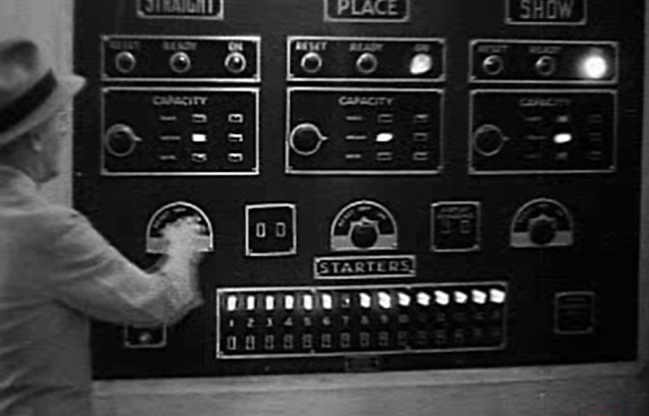
The image above shows a Julius Tote Control Room Switchboard at Hialeah Racecourse Miami, in the United States of America. Although the image above is low resolution, I think it is better than having no image at all. At the top of the image above there are three signs above the corresponding pool related equipment, that read STRAIGHT, PLACE and SHOW. In this system, the Straight Pool is the same as the Win Pool, the Place Pool pays on a runner selection that comes first or second and the the Show Pool pays on a runner that comes first, second or third. Below each of these pool names is a panel with three lights labelled RESET READY and ON. It can be seen that the left panel has no light illuminated and the two panels on the right have the ON light illuminated, indicating that the totalisator is on-line or in other words the betting is on for those pools. The RESET READY and ON lights are described below under the heading 'RESET', 'READY' and 'ON' SIGNAL LAMP CIRCUITS./ Drawing NO. 3488, extracted from the company document titled Automatic Totalisators Limited Description of Electrical Circuit Diagrams.
The next three panels below the last three in the Control Room Switchboard image above, are the capacity setting switch and indicator panels for each pool, with the word CAPACITY at the top of every panel in the row. Each of these panels has two columns of three lights in the right hand half. The left hand column contains the request lights from the Control Room to the Machine Room and the selected lamp will illuminate when the selector knob on the left is moved to point at the lamp. As can be seen in the image above, the selector knob pointer on all three selectors is pointing directly to the right without any up or down displacement, consequently the centre lamp in the left hand column is lit in all three panels. The right hand column of three lights are the response lights from the Machine Room, where the mainframe equipment is located. All three lights in the right hand columns of lights in each of the CAPACITY panels are extinguished, presumably because the image shows the system at the end of a race and configuration for the next race has not yet begun. In each column of lights there will only be one light lit at any time. When the system is properly configured the pairs of illuminated lamps for each of the three pools will line up horizontally. On the left hand side of the columns of three lights in each panel, there is a column of descriptive words forming a third column. The words are not even close to being legible in this image above, however they will identify which row represents a Maximum Mean or Minimum configuration. These are described in the paragraphs above titled CAPACITY SIGNAL CIRCUIT./ Drawing NO. 3487 and are often referred to as MAX MEAN and MIN in other references. Note that the blueprint drawing at the top of this page only shows a system with two pools, Win and Place, while the Control Room Switchboard in the image above has a third pool named SHOW on the right hand side.
At the bottom of the control panel shown above the starters lights and switches can be seen. These allow the actual runners in the race to be configured. From the STARTERS panel shown above, it can be determined that the system has been configured for a field size of fifteen and runner seven has been scratched as the number seven light is extinguished. This is described above under the heading ESCAPEMENT ALARM & STARTERS LAMPS/ CIRCUITS / Drawing NO. 3486 and the sub heading Starters Lamps.
The knob the manager in the image above has his hand on is the betting control knob, of which there are three one for each pool. The image above is a frame extracted from a short film, and in the scene to which this frame belongs, the manager is turning the betting off. As can be seen in the frame above, he has already turned it off for the STRAIGHT pool, as its ON light is no longer illuminated in the associated RESET READY ON panel, the second panel above the switch he is holding, whilst the ON light for the other two pools shown in the panels to the right are still illuminated. Watching the video clip from which the above image is extracted, he then proceeds to turn the betting off for the PLACE pool and the SHOW pool by rotating the associated knobs anticlockwise which turns off their associated ON lights. As it is not possible to read the writing on the knob positions of which there seem to be four, I suspect the right hand or furthest clockwise position of the knob, is the ON position. Obviously one of the remaining three positions will be the OFF position and a second must be RESET. As the READY signal comes from the Machine Room, there will be no switch position for that in the Control Room, leaving it unknown what the fourth position is.
This film clip to which the image above belongs, can be seen by selecting the Go to the index button in the Nav Bar at the bottom of this page, then selecting the Video clips of a working Julius tote chapter in the Thirdly section of the index. This video clip is titled hialeah1932.wmv (18.3Mb)Opening Day Hialeah Park 1932 and is the last in the index of video clips.
Following is the continued transcription of Automatic Totalisators Limited Description of Electrical Circuit Diagrams:
'RESET', 'READY' and 'ON' SIGNAL LAMP CIRCUITS./ Drawing NO. 3488.
On the Control Room Switchboard there are two sets of three signal lamps marked 'Reset', 'Ready' and 'On', one set being for Win and the other for Place. There are six corresponding lamps on the Machine Room Signal Board connected in series with the above lamps.
When a race commences the machine is closed by the Steward, as described elsewhere. The Manager then turns his Win and Place control switches to the "off" position and the Head Mechanic also turns the Control Switches on the Main Switchboard to "off" position. In this position none of the signal lamps are alight.
When the manager has been notified by the dividend calculators that they have obtained the figures from the Adding Units, he turns his control switches to the 'Reset' position which lights the 'Reset' lamp on the Control Room Switchboard and the Machine Room Signal Board, thus notifying the mechanics that the machine may be reset for the next race.
On each Odds Unit there is a reset switch which is only closed when the horse slider is pulled right back to the reset position. All these reset switches are connected in series with the two 'Ready' lamps and in series with the Control Switches on the Main Switchboard. When the head mechanic is satisfied that the machine has been properly reset and is ready for the next race, he turns his control switches to the 'On' position and the 'Ready' lamps then light up provided that all horse slides have been set to zero. This notifies the Manager that the machine is ready for betting on the next race.
When the Manager is ready to open betting on the next race, he turns his control switches to the 'On' position and this, as described elsewhere, completes the circuit for the coils of the Win and Place contactors on the Main Switchboard. These...
Alas Alack, it looks like there is more but there isn't. Either the following page was missing or it wasn't worth photographing.
In the first paragraph below the last heading it mentions two sets of three signal lamps marked 'Reset', 'Ready' and 'On', one set being for Win and the other for Place. As the Tote Control Room Switchboard shown in the image above was built for the American market, it has an additional pool called Show Pool, consequently it has three sets of three signal lamps marked 'Reset', 'Ready' and 'On'.
In the second paragraph below the last heading it states the Manager then turns his Win and Place control switches to the "off" position. This is exactly the action that is seen in the video clip from which the Switchboard image above was extracted, except there is an additional control switch for the Show Pool. In the image above the manager has already turned the control switch he has his hand on, to the Off Position as the On light in the second panel above his hand is extinguished.
In the third paragraph below the last heading it states he turns his control switches to the 'Reset' position which confirms what I have deduced at the end of the fourth paragraph below the image above, that the Reset switch is closed by the knob he presently has his hand on, which this old company document refers to collectively as control switches.
The Ready Lamps mentioned in the fourth paragraph below the last heading can be seen in the Switchboard above, it is the middle light of three in the second panel above the manager's hand which is for the STRAIGHT pool as well as the two panels to the right of it for the PLACE and SHOW pools.
In the fifth paragraph below the last heading it states when the Manager is ready to open betting on the next race, he turns his control switches to the 'On' position. The 'On' lights, which are the right hand of three lights in the second row of panels above the three Control Switches, are illuminated for the PLACE and SHOW pools indicating their respective Control Switches are in the ON position.
What I find amazing about all this is what I call Engineering Artwork. The blueprint drawings above are 1930s engineering drawings. This sort of engineering documentation heavily oriented around drawings, go back to the origins of Automatic Totalisators Limited in 1917. George Julius' engineering consulting company Julius Poole & Gibson, published a book called Julius Poole & Gibson The First Eighty Years. This book had a subtitle From Tote To CAD. This subtitle seems particularly pertinent when thinking about the drawings produced. I remember the Drawing Offices producing these drawings that used to be sizeable departments, which used to be a hive of activity. I believe Art definitely exists in Engineering and that this is particularly the case with Engineering Drawing/ Technical Drawing. The personal computer and the readily available CAD/CAM software put an end to the need for Drawing Offices. When Neville Mitchell was made the Automatic Totalisators Limited Drawing Office manager, he had 27 draughtsmen working for him. The image below shows the Automatic Totalisators Limited Drawing Office prior to Neville's time as manager.
The Automatic Totalisators Limited Drawing Office
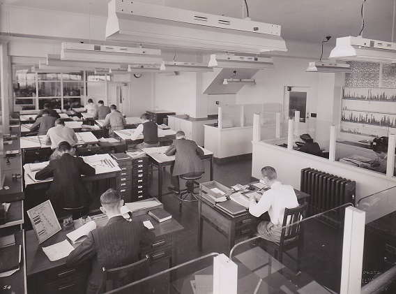
On the subject of Engineering Drawings, it reminds me of an Anecdote from Jim Loveday, who was a Partner of Julius Poole & Gibson, which is extracted from the book Julius Poole & Gibson The First Eighty Years:
Jim Loveday had a cheery and affable personality. He loved to tell a story of the early days when he was working under the usually strict and demanding eye of George Julius. The following anecdote took place at Culwulla Chambers.
Sir George had a buzzer installed which he used to summon us to show the progress of our work. One day the drawing I had just finished blew out of the window and floated down Castlereagh Street where it was run over by a tram. I rushed down stairs, retrieved the remains of the drawing and got back just in time to hear the buzzer sound twice which was the signal for me to present my work.
Sir George slowly eyed the mutilated drawing in my hands and simply remarked dead pan "You've made quite a mess of this drawing, Loveday, I expect to see some improvement in future".
Having introduced Jim Loveday, who was a Partner of Julius Poole & Gibson, I will remind you that the blueprint drawing above titled Julius Poole and Gibson blueprint, as well as the one at the top of this page were drawn by Awdry Julius, George Julius' son who worked for Julius Poole & Gibson.
One final word about art in engineering, I had a friend Brian Wetless who taught me much about aviation. He bought a brand new Honda CBX6 motorcycle, the top of the superbikes of its time. Apart from being a pilot he was a keen motorcyclist and yet he never rode his superbike! Instead he located it in the middle of his lounge room on a white carpet. There it remained on display as his most prized piece of artwork. He used to ask my friends think I am nuts, what do you think? I consider myself to be somewhat of a dullard so far as art in general goes, however I have always seen magnificent art in engineering and Aboriginal art. When the CBX6 became a classic, members of the CBX6 motorcycle club came to see his CBX6 to see how they looked straight out of the factory, so they could restore their machines to factory condition.
After all the work in September/October 2018 related to implementing the recently rediscovered technical information from Emeritus Professor Bob Doran in this new additional page in the Totalisator History website, as well as incorporating it into other pertinent pages of the site, I now find myself after all this latest investigation resulting from Bob Doran's Riccarton documents and Garry Elliot's J8 assembly document that I feel confident I could get a job anywhere in the world as a Julius Tote Engineer. As Maxwell Smart from the TV series Get Smart would have said, a plan with one minor problem! I am retired and thoroughly enjoying it as well as being over half a century too late.

There are pertinent extracts from the company document titled Automatic Totalisators Limited Description of Electrical Circuit Diagrams presented in this page, that appear in three other pages of the Photo Album of this website. These contain images related to the extracts with additional associated explanation. They follow this page in sequence accessible by selecting the Next page option in the navigation bar at the bottom of this page and at the bottom of the following two pages. The next page relates to the Julius Tote Ticket Issuing Machines, the following page to the Julius Tote Adders and the page after that, to the Julius Tote Distributors/Scanners. If you wish to remain in the Photo Gallery after the third page, do not select the Next page option, click on the image at the top of the page instead.
There is another page in this website which includes the three extracts above for Drawing Numbers 3486, 3487 and 3488 which describes them with respect to a different way of implementing the Control Room Switchboard. It is a device called an RDC console an acronym for Race Day Control. This was a self contained device which implemented much of the functionality of the Control Room Switchboard which I suspect was a later development to make it easier to relocate the Control Centre. As I have at least seen these RDCs, although not in action, I know more about them and as I have better images of them than the Control Room Switchboards, I have gone into greater detail in that page. To view this, click on the Go to the index button in the Nav Bar below and select the Photo Gallery + Synchronicity entry in the Finally section of the index. Now scroll down in the Photo Gallery index, to the heading Harold Park Harness Racing Track then select the tall thumbnail below, with the associated text starting with the sentence A Raceday Control Console at Harold Park 1958. The extracts and descriptions are immediately below the image at the top of the page.
There is also a page in this website which gives an operational view of the Julius Totalisator, which complements this technical view of the equipment. To view this, select the Go to the index button in the Nav Bar below. Then select the The Premier Tote Operation 1930 + Neville's talk chapter in the Firstly section of the index. This operational view starts at the top of the page with the heading The Premier automatic totalizator operation 1930.
If you are interested in the adders and other Julius Tote equipment described in this page, there is a transcript of George Julius' white paper that relates to the Julius Tote, that can be read in the Mechanical Aids to Calculation chapter of this website. To read this, click on the Go to the index button in the Navigation Bar below then select the Mechanical Aids to Calculation chapter in the Firstly section of the index.
Comments and suggestions welcome to totehis@hotmail.com