This technology history page contains an image, which is one of several belonging to the photo gallery pages, which are part of several pages relating to the invention of the world's first automatic totalizator by George Julius in 1913 and Automatic Totalisators Limited, the Australian company he founded in 1917 to develop, manufacture and export these systems.
Electro Mechanical Computing on an Industrial Scale
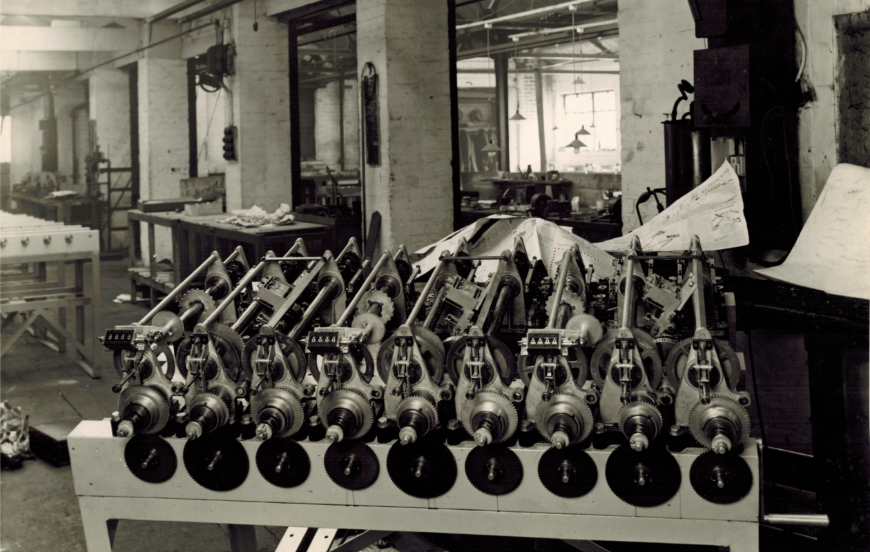
Brough Park Newcastle 3-3 shaft GT Adder
This image is of a Grand Total Adder for Brough Park racetrack Newcastle Upon Tyne. The installation of this system was in 1936. The photograph was taken inside the Automatic Totalisators Limited factory in Chalmers Street, Surrey Hills, Sydney. The writing on the back of the photograph reads: Brough Park Newcastle - View of 3-3 shaft Grand Total machines on one frame (W.P.&F.) - Note that middle shaft of each section is speeded(sic) up. This is to enable that shaft to hold 10/- betting without unduly running the storage screws in.-Grand Totals have two units shafts (each 3 escapements) and one tens shaft to keep speeds down as at White City. W.P.&F. in this text stands for Win Place and Forecast pools. The Grand Total Adders summed all transactions that were recorded on each of the runner specific Adders, which summed the total investments on their respective runners. The three counters on the front of this GT adder display the total investment on the Win, Place and Forecast pools which are required for calculating dividends for these pools.
A look at a mechanical storage device long before the electronics that made storage a common concept
The writing on the back of the photograph refers to the storage screws, which are very interesting devices for technologists interested in the history of computing. If you are interested in the storage screw or the workings of the adder read further in the text below the image.
Click on the image to go back to the Photo Gallery
There is no photographer's stamp on this photograph
I am intrigued by the analogies between these mechanical/electromechanical systems and computer systems. The word storage, often rolls off the tongue of computer technologists. One of the most widespread uses of the word in this field is in the concept of mass storage. Another example are General Purpose Registers which provide fast temporary storage often used to store operands. Whatever the application of the word Storage, in digital computing it requires a form of memory. I suspect none reading this will have heard the term Storage Screw, so in computer terms it can be thought of as a buffer memory. For those readers not familiar with digital computer design, buffer memory is regularly found in digital computers as a temporary store for data that is being transferred between devices of disparate rates of processing or transfer. This is exactly what the Storage Screws do, storing transactions during rapidly changing rates so that other slower to respond parts of the system can catch up or slow down and come to a gentle halt. Having made the analogy of buffer memory being the electronic counterpart to the storage screws, I can take this a step further with an extract from the writing on the back of the above photo. The following sentence extracted from the quoted text above from the back of the photo This is to enable that shaft to hold 10/- betting without unduly running the storage screws in, refers to unduly running the storage screws in. If a storage screw is driven all the way in, then the buffer memory analogy to this is a Buffer Overflow Error.
The Storage Screw was designed to solve a problem associated with inertia. The adding shafts with their escapement wheels and epicyclic gears could respond quickly to the demands of betting as they were relatively low in mass. When it came to large counter wheels in indicator displays these had to overcome significant inertia. In simplistic terms, as transactions in the Julius Tote are recorded as increments of rotation or in other words angular displacement of a shaft, a headless screw is wound into a long tubular shaped nut by an associated fast response shaft adder capable of keeping up with the requirements of the bet traffic. At the other end the comparatively large tubular nut is simultaneously unwound from the screw, working to initially slow the screw's progress into the nut and eventually return the screw to its starting position, when the angular velocity of the nut exceeds the velocity of the associated adding shaft. The screw remembers the rotation generated by the fast adding equipment and is read by the acceleration limited heavier equipment. In more general terms the principle is that the angular displacement to which a screw is screwed into a nut is equal to the angular displacement in the opposite direction the nut needs to be rotated to return the screw to its original position in the nut. Similarly, as the screw returns to the vicinity of its starting position the nut velocity is reduced at a rate the heavier equipment can achieve. To have a look at an Engineering Drawing of this storage screw, click on the image above and scroll down to the index heading Figures from George Julius' White Paper 1920 and a Julius Tote Engineering Drawing and click on the first thumbnail in this section with the descriptive text starting with the sentence The images in this section are for the technically minded.
Following are some comments in the words of George Julius, extracted from a paper he presented to the Institution of Engineers Australia on Thursday May 13th 1920 titled Mechanical Aids To Calculation, when a machine that had been built and tested capable of supporting 1,000 terminals and a sell rate of 250,000 bets per minute was demonstrated:
In other words, the mechanism that stores up the records has to control a variable speed gear, which will as required gradually speed up or gradually retard the counters, and so avoid all shock to the mechanism.
...
The epicyclic gears are made as light as possible, and are urged forward by " coil springs " and not by "weights." This ensured the instantaneous response of the epicyclic gears to the demands of the ticket-sellers. The movement of these gears so obtained is transferred to a " storage " screw which serves two functions, firstly, that when the machine is at rest it locks the driving gear which operates the counter wheels, and, secondly that when issues are to be recorded, it stores-up the records until they are registered by the counters. Immediately the tickets are issued the epicyclic gears instantly operate, being driven by the coil spring, and in so doing they turn the screw which then unlocks the driving gear for the counter, and the counter begins to operate. In so operating, this driving gear also moves a nut, which, acting on the storage screw, tends to bring it back to its normal position of rest, and thus again lock the counter driving mechanism. Thus the epicyclic gears in picking up impulses received from the ticket-sellers move the screw backwards, and the, driving gear of the counter is always trying to overtake this movement and thus return the screw to its normal position.
The movement of this screw is so arranged that it also controls a variable speed friction gear through which the counters are driven. During any period of acceleration in the issue of tickets, the screw is withdrawn in the nut faster than the counter operates, and this through the friction gear speeds up the counter, and the nut, in an endeavour to overtake the movement of the screw, and a condition of balance is ultimately established. If the issue of tickets is retarded or ceases, the nut immediately gains on the screw and brings it forward, thereby picking up all the stored-up records, and by means of the friction gear gradually slowing down the counter until when all the records are recorded, it quietly comes to rest. The rotation of the nut also is utilised to continually rewind the coil spring which operates the epicyclic gears, and thus ensure a steady driving effort on these gears.
The whole operation is entirely automatic and the speed is adjusted to suit the requirements of the ticket issuing. The arrangement of gears, screw , and nut is shown diagrammatically in Figure No. 10, and in more detail in Figure No. 11.
The part of George's paper that is pertinent to this website is presented in the Mechanical Aids to Calculation Chapter of this website.
Before proceeding there is a potentially confusing terminology regarding the word adder, which I will clear up. The device shown in the image above is called an Adder. This Adder contains nine constituent shaft adders that sum transactions from groups of TIMs (Ticket Issuing Machines). The Shaft Adders as the name implies contain the adding shafts. Similarly some confusion can result with the name Storage Screw and the word Screw. Storage Screw refers to the complete device including the long tubular nut and its internal headless screw as well as the cogs, shafts and control equipment whilst the word Screw refers to the internal screw inside the Storage Screw.
The Storage Screw assemblies can be seen as tubular shafts in the image above, that connect the adding shafts with their associated escapement wheels and epicyclic gears at the rear far side of the adder, to cogs on the near side or front of the adder frame. The nine front mounting plates for each of the nine storage screws look like rounded-top church steeples, with a large circular window in the upper part of each of them and are located behind their respective nine shiny cogs across the front of the adder. Each shiny cog meshes with an associated lower black cog and each lower black cog is attached to the front of the adder support table. In my analogy to the front mounting plates each looking like a church steeple, the windows in the church steeples are the front mounting points for the nine storage screws. On the inside of each mounting plate, behind these front mounting points, are the largest cogs in the adder and each of these are connected to their respective Storage Screw Nut as George Julius calls them. These cogs almost reach to the top of their respective front mounting plates and are the nut drive cogs which unwind their respective nuts from their respective screws. The nut is the outer tubular section of each Storage Screw. At the top of each Storage Screw mounting plate, which is the peak of the spire in the church spire analogy, there is a rod that is part of the assembly that secures the rear mounting plate to the front mounting plate. The storage screws are located below and run parallel to these mounting rods. In other words the body of the Storage Screws are the longest and widest cylindrical shafts running from the individual constituent shaft adders at the rear of the adder to the large cogs at the front, which are the highest cogs in the adder. The nine black cogs attached to the front of the table provide the drive for their respective storage screws and keep their shaft adder springs wound up. The black cogs will most likely have been driven by an electric motor under the table when this adder was installed at Brough Park. When I first read the note on the back of the photograph that is quoted above, I found the comment Note that middle shaft of each section is speeded up, interesting. I wondered how you could tell that the middle shaft of each section was sped up. When I realised that the cogs on the front of the table were the drive cogs it became obvious. The gear ratio of each pair of black and shiny cogs in the middle of a group of three differed from the ones either side. These middle pairs of meshing cogs in a group of three pairs, have a larger driving cog (black) and a smaller driven cog (shiny) than the others, which means these middle driven cogs will rotate faster than the ones either side of them. So we now know that the first and third storage screws in a group of three and their associated shaft adders total units and the middle one of three totals tens of units which for Brough Park would probably have been shillings. Additionally there are three groups of three one group of three for the Win Pool, another group of three for the Place Pool and the final group of three for the Forecast Pool.
As I have mentioned the adding shafts above, that summed the transactions from the TIMs, if you wish to have a look at an Engineering Drawing of the epicyclic gear arrangement and escapement wheels on this shaft, click on the image above and scroll down to the index heading Figures from George Julius' White Paper 1920 and a Julius Tote Engineering Drawing and click on the second thumbnail in this section with the descriptive text starting with FIG 9 from George Julius' paper.
Revisiting the extract from the note on the back of the photo middle shaft of each section is speeded(sic) up I find it interesting that this adder needs a units shaft that is sped up to accommodate the sale of 10 shilling bets when the note states Grand Totals have two units shafts (each 3 escapements) and one tens shaft to keep speeds down indicating the GT Adder also has a tens shaft. It begs the question why do we speed up a units shaft to accommodate 10 shilling bets when it has a tens shaft? I think I know the answer to this. The Julius Totes before the introduction of a value switch on the TIMs had some machines dedicated to high value bets and they were associated with a high value escapement wheel in the machine room adders. These would be associated with the tens shaft mentioned in the note on the back of the photograph. Regarding the TIMs associated with the units shaft, if the punter wanted a higher value bet than a shilling the operator would not release the issuer handle after the first ticket was printed and the TIM would continue to cycle registering unit bets and printing the tickets until the handle was released. In other words TIMs in areas where bets tended to be above one shilling, but not warrant a machine dedicated to ten shillings or higher only, would be associated with the sped up Units Shaft. TIMs in areas where most transactions are for one shilling would be attached to the second Units Shaft running at normal speed. I presume the reason you did not speed up all the units shafts is that it increases wear and tear on the associated machinery.
The following is my simplistic and speculative conceptualisation of the storage screws, as I have never worked on any of the Julius Totes or seen one working. I worked on the computer totalizators after Julius tote production had ceased. I find the analogy of the nut and screw a little hard to comprehend however I think this is because of some preconceived ideas. One thinks of a nut as relatively short and a screw as relatively long. Additionally one tends to think of one end being stationary with the screw being held in position whilst a nut is tightened on it or the screw rotating into a fixed or held nut. The nuts in this system are long and the screws short and both rotate. The nuts in this equipment are the long tubular sections as previously identified in the image above, which are threaded on the inside. Each of these tubular nuts rotate in the opposite direction to the associated adding shaft that drives the screw into the nut, effectively working to unwind the screw until it returns to its resting position when the respective adder has ceased to record transactions due to a lull in betting. The screw is small in comparison to the length of the tubular nut, allowing it considerable movement up and down the nut and is more like a grub screw. This storage screw is wound into the nut, driven by its comparatively high acceleration shaft adder output shaft. The storage screw probably has an internal parallel key-way. The driving shaft for the storage screw, attached to the shaft adder output shaft is probably keyed and passes through the centre of the screw, the key enabling the driving shaft to turn the screw whilst allowing the screw to travel up and down the tubular nut, guided by the threads of the nut. If anyone has any ideas on this conceptualisation, I am thankful for any suggestions for improvement. To send email, click on the image above and scroll to the bottom of the Photo Gallery page and use the email link there.
I have seen 1940s era Julius Totes and although I have not seen the sort of adder shown at the top of the page, I am certain of the following observation. Protruding from the nine driven shiny cogs across the front of the adder, that are the ones engaged with the black driving cogs underneath, are spindles with springs on them. These are clutch springs that apply an adjustable pressure to clutch plates inside the centres of the shiny cogs. When the storage screw returns to its rest position the control mechanism locks the storage screw's tubular nut from further rotation until more transactions take place. The locked storage screw tubular nut causes the clutch to slip disengaging the storage screw from the constant drive of the electric motor causing constant rotation of the respective black cog engaged with the respective shiny cog with its clutch. When the clutch is slipping it does not pass the constant rotation of the shiny cog to the large cog attached to the storage screw's tubular nut. Regarding these shiny cogs seen across the front of the adder above, with their respective clutches, the spindles they are mounted on continue through the respective mounting frames and terminate with very small cogs on them that engage their respective large cogs on the inside of the mounting frames, that are attached to the respective storage tubular bodies. The part of each of the spindles with the small driving cog is on the opposite side of the clutch so these are capable of stopping and starting as required. I am quite amazed at the gearing of the small drive cogs to the large storage screw body cogs. By measuring the diameters of these cogs in a high resolution image of one of the adders at White City I determined the gear ratio is 1 to 7.5 which means the drive cogs on the front of the adder rotate much faster than the large drive cogs attached to their respective storage screw tubular body. I can point out where these cogs mesh in the image below however the resolution makes the small drive cog just look like a little black spot when significantly zoomed in. In the image below, the nearest adder in the middle row of adders with the identifying lamppost reading 6W, look at the nearest storage screw attached to the front of the whole adder and its associated constituent shaft adder at the rear, the large cog at the far left hand end of the storage screw can be seen. What appears as one cog, if you look closely you can see is actually two cogs. The cog nearest the front of the adder is slightly larger and is the one that meshes with the small drive cog at about 45 degrees below horizontal on the near half of the large cog. Whilst you are focused on this part of the adder, below this large cog, you can see a shaft running to the right underneath and perpendicular to each of the storage screws near the front of the adder. This shaft is another adding shaft that has epicyclic gears in it that sum the rotation of each of the Unit storage screws, up to where the tens of units are transferred to the Tens shaft. Part of the gearing on this additional adding shaft can be seen in the adder discussed so far as well as in the adder to the right that has 6P on its identification lamppost. I must point out that these complete adders on the two right hand rows of tables in the image below are totalling runner totals for the Win and Place pools respectively at White City, whilst the adder at the top of the page is a Grand Total adder destined for Brough Park, so there are differences between them particularly in this additional adding shaft running across the front of the complete adder just referred to.
If you are interested in this horizontal shaft, one is described in detail in another image file of the Photo Gallery. Click on the image at the top of this page, scroll up above the heading Brough Park Newcastle Upon Tyne 1936 and select the image thumbnail in the next group of photographs below the title starting with the text White City Stadium London 1933, showing an adder with the associated descriptive text starting with the sentence Another view of the adding equipment, part of the central processing system at White City Stadium London 1933. Finally, scroll down below the second image in the page just loaded and read the paragraph starting with the sentence The Plan View image of this adder presents a good view of something that ties the individual constituent shaft adders and their associated storage screws together.
Above the shafts with springs and to the left in the image above, there are rods that extend outwards from the centre of each storage screw and are parallel to the shafts the clutch springs are on. These are part of the mechanisms that sense the position of their respective storage screws, when their respective screw is close to its rest position. For the sake of this description I will refer to these rods as Position Sensing Rods. These Rods lock the driven equipment of their respective storage screw when the respective memory is empty as mentioned in the previous paragraph and is also a part of the feedback path that controls the velocity of the respective storage screw driven equipment to slow it down when the storage screw is nearing its rest position. I can point out how the Position Sensing Rods lock the Storage Screw Drive with the aid of the following photograph in the Photo Gallery. Firstly, I will refer to the two left hand Position Sensing Rods in the image above. This may be easier to see if you zoom in on these rods. All the position sensing rods in the image above, are shown in a position where their respective storage screws are close to their rest positions, in other words they will extend a little further out at their rest positions. The Position Sensing Rods pass through a lever consisting of two metal strips projecting downwards from a hinge that is supported by a bracket attached to the front mounting plate for each storage screw, a mounting plate that I likened to rounded-top church steeples. The attachment point for this hinge mounting bracket is near the peak of the steeple. For the sake of this description I will call the lever mentioned the Stop Lever. It can be seen that the Position Sensing Rods pass through a collar mounted in between the strips of metal constituting the Stop Lever. The collar looks like a square nut but it has no thread and the Position Sensing Rods pass through their associated collars and can move in and out through the centre of the collar. As I cannot ascertain how the Position Sensing Rod actually activates the Stop Lever, I speculate that the Position Sensing Rods have a thicker section behind the nut in their present position in the image above. I speculate further that with heavy betting the Position Sensing Rod moves further into the storage screw body until it reaches an end stop. With heavy betting the internal screw component can be wound further into the body of the whole Storage Screw, by its respective adder, and it is no longer in the vicinity of its resting position and the Position Sensing Rod rests until the internal screw returns to push the Sensing rod out again. As the inertia limited equipment that the storage screw drives, starts to catch up and eventually exceeds the velocity of the associated adding shaft, at which time the internal screw component starts to be returned to its starting position. Eventually, when the internal screw returns to the vicinity of its rest position, it starts to push its respective Position Sensing Rod back out again. The Position Sensing Rod continues to move through the round centre hole of the square collar on the Stop Lever until it eventually gets to the wider part of the Position Sensing Rod and as it no longer fits through the collar hole, it pushes the bottom of the Stop Lever towards the back of the silver cog. As the following image to this one in the Photo Gallery shows a view from the top of this complete GT Adder, it is possible to see the bottom of this lever. The bottom of each Stop Lever has a semi circular metal protrusion which is a stopper extending towards the back of the associated silver cog. Each of the nine silver cogs have a corresponding semicircular stopper on the back of them. If a Position Sensing Rod has pushed its stopper on the end of its connected Stop Lever into its activated position, the flat part of the silver cog stopper on the lever, eventually engages the flat part of the stopper on the back of its associated silver cog, when the rotational cog motion brings its stopper to the position of the lever stopper, and the rotation of the cog stops. This is where the clutch mentioned in the last paragraph comes in, as the clutch slips when these stoppers engage. This is what George Julius refers to in his quote above when the machine is at rest it locks the driving gear which operates the counter wheels. If you wish to see the stoppers, click on the image above and select the thumbnail for the following image in the Photo Gallery index. Finally search for the word stopper.
The machine room at White City London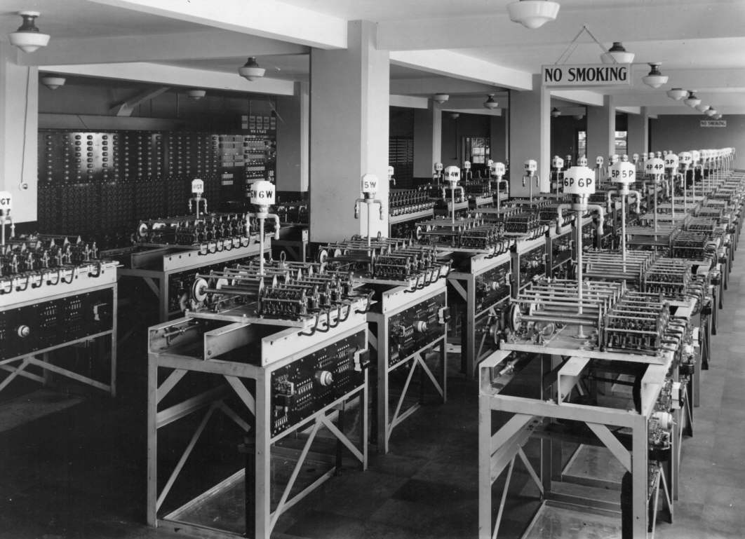
The above image shows the White City Julius Tote Machine Room. It is here to put the image of the GT adder at the top of the page into context, to see what the central processing part of a Julius Tote looks like and how large these systems were. I do not have an image of the Brough Park machine room, however at least this system was also in England. These are only some of the adders in the White City system and does not show all the ancillary equipment panels. Part of the ancillary equipment panels are just visible on the left hand wall, however it shows little detail. The adder at the top of this page is a Grand Total adder which means it sums the totals of all the other adders usually in a particular pool. It is interesting to note that the Brough Park GT adder totals three pools Win Place and Forecast whilst the White City installation has dedicated GT adders for each of these pools. This is because the Brough Park system was much smaller than the White City one, Brough Park had 8 TIMs and White City ended up with 320 TIMs, none of which are in this machine room in the image above, but located around the White City track at selling windows in dedicated tote houses. The Julius Tote Machine Rooms are the counterpart of the present day mainframe computer room.
The far left hand adder in the image above at White City, with part of the adder not in the image, is also a Grand Total adder which is for the Place Pool. The sign on the top of the lamplight signpost rising from the adder reads PGT to identify it as the Place pool Grand Total adder. The P is not shown in this image. The adder immediately to the right of this one, has WGT on its lamplight signpost, identifying it as the Win Grand Total adder. When the system is in use, these lights on top of the adders will be illuminated for every adder in use for a race, indicating it is active. Adders corresponding to runner numbers greater than the number of runners in the race, as well as adders corresponding to scratched runners will not be illuminated and remain disabled. The number of runners will be selected on the control panel, which is not visible in this photo. Looking at the two complete rows of adders on the right hand side, the first adder in the left row has a signpost that reads 6W, indicating that this adder is totalling the investments on runner number 6 for the Win pool in the race. The first adder on the right hand row has 6P on its signpost indicating this adder is totalling investments for the Place pool on runner number 6. The adders in the White City image are very similar to the Brough Park adder at the top of this page. Looking at the 6P adder in the image above you can see a side view of the similar adder shown from the front at the top of this page. In the 6P Adder you can clearly see the six constituent individual shaft adders on the right hand side occupying about one third of the depth of the adder with the remaining two thirds taken up by the corresponding six storage screws extending from the left hand side of the constituent shaft adders to the left hand side front of the 6P Adder. The six constituent shaft adder assemblies of this 6P Adder are lower than the six storage screw assemblies. This can also be seen in the GT adder image at the top of this page. Remembering my analogy of the church steeples to the mounting plates of the storage screws, looking at the 6P adder in the image above, the point where the height of the adder increases is where the component shaft adders connect to their corresponding storage screws and it is the church steeple like rear mounting plates of the storage screws that create the increase in height. One obvious difference between this 6P Runner Adder above and the GT Adder at the top of this page, is that as previously identified the GT Adder has nine constituent shaft adders with nine storage screws, not six of each as in the 6P Adder.