This is one of several pages relating to the history of the automatic totaliser, its invention in 1913, the inventor George Julius and the Australian company he founded in 1917 which became a monopoly (later part of an oligopoly) in this field. This page has a wider appeal relating to the history of technology and computing machinery. This page contains extracts from a paper presented to the Institution of Engineers Australia in 1920 titled Mechanical Aids To Calculation. It also contains a newspaper article in which Sir George Julius describes his background in this subject. If you wish to start from the beginning of this website then go to the index
Copyright © 1997 Email - totehis@hotmail.com
Before getting started, I would like to note here that the word totalisator is synonymous with totalizator, totaliser, totalizer and the contraction tote. I have deviated and used totaliser in the title of this page for the sake of the search engines.
Additionally, the first time I started transcribing these old documents such as this one, and totalisator operation 1930, into HTML I found myself making corrections to the text. I soon realised that these corrections were repetitive and that the language had changed a little since these documents were produced. Consequently I have left them in the original form.
The following are extracts from a white paper presented to the Institution of Engineers Australia on Thursday May 13th 1920 by George Alfred Julius - Member.
After this paper, I have also provided a newspaper extract, in which George Julius relates how the world's first automatic totalisator was invented. This may be more interesting for the non technical reader who does not wish to get involved in technical details.
George Julius' white paper titled Mechanical Aids to Calculation was published by the Sydney Division of the Institution of Engineers Australia. George Julius was an instrumental founder of the Institution of Engineers Australia. Thanks to the Institution of Engineers Australia for approving reproduction of this document.
In this paper, George describes a system built and tested in Sydney capable of supporting one thousand terminals and a sell rate of two hundred and fifty thousand per minute in 1920. I spent most of my working lifetime on computer based totaliser systems and the transaction rate of this 1920 system was good by the standards throughout my time.
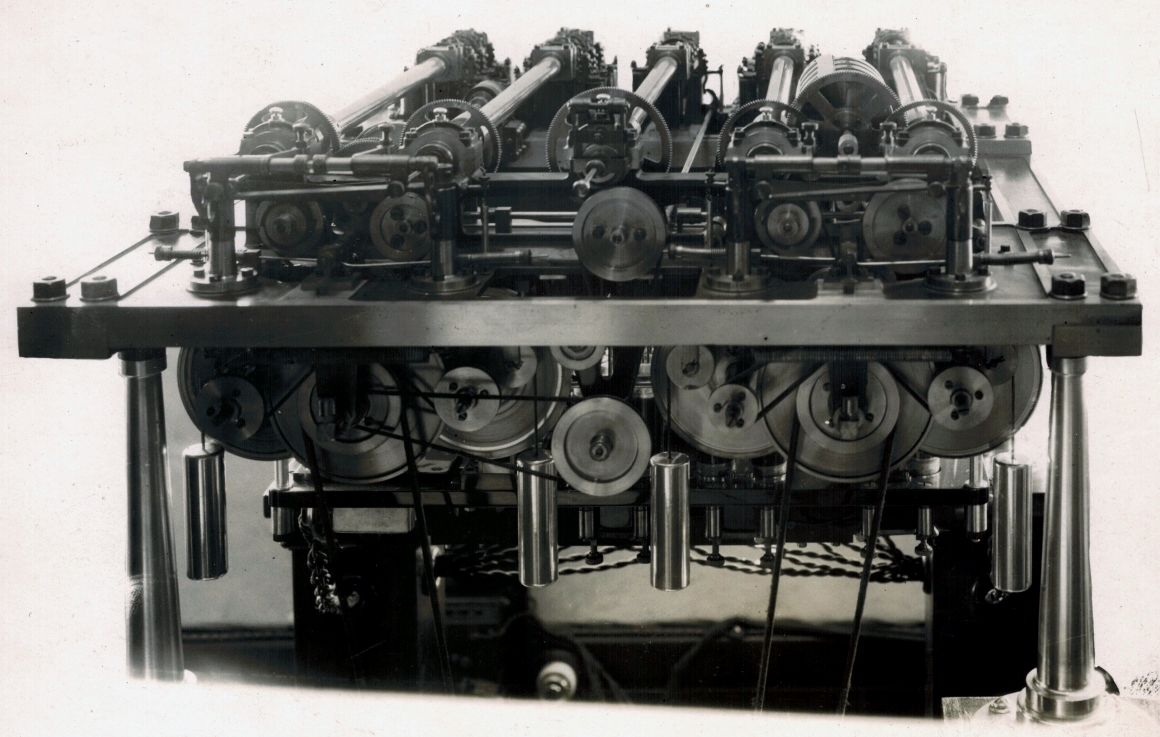
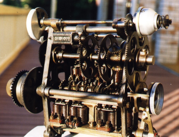
The image above shows an early electromechanical shaft adder which was used for this presentation to the Institution of Engineers Australia. I have always found this photograph of an adder particularly attractive as the adder looks so ornate with the elaborate shiny legs on the adder mounting frame. Additionally, this is the only adder I have seen, which still utilises weights for motive force indicating that it is a very early adder at the beginning of the transition to electromechanical systems. All other adders I have seen have an electric motor providing the motive force. Having mentioned the weights, of which there are four, they too add to the ornate appearance of this adder as they too look shiny, polished and artistically suspended.
The electrical element in this adder is at the rear and part of this can be seen in the twisted pair cables dangling below the rear of the adder. The first of the electromechanical Julius Totes was the 1917 Randwick system, which I regard as the world's first large scale real time multi user system. This adder implemented a major improvement in system design, resulting from contemplations of systems larger than Randwick. This improvement involved what nowadays is termed TDMs or Time Division Multiplexers. George of course does not refer to them as such, as it took over three decades for the electronics industry to become established and for digital electronics to make that concept commonplace. George refers to them below as a distributor. It is the impulses from the distributors (TDMs) that are carried in the twisted pair cables visible beneath this adder. I suspect these TDMs were the world's first. It is difficult to convince contemporary technologists that TDMs pre-dated the electronics industry and were originally implemented electro-mechanically. And now handing over to George Julius:
| Mechanical Aids to Calculation |
Sir George Julius
| Summary |
Of recent years, however, a need has arisen for an adding machine which will pick up and add the records passed on to it by a number of independent operators. Particular applications of this requirement are found in railway ticket printing and issuing, in the recording of sales in large departmental stores, and in racecourse totalisator practice. The paper describes the development of a machine that has been built in Australia capable of meeting such requirements and of recording records received from as many as 1000 independent operators, and at speeds as high as 4000 a second. These machines are capable of both printing and issuing tickets, and at the same time recording the issue of such tickets when issued in great numbers and simultaneously by a number of selling machines.
The machines are equipped with safety gear of various kinds to prevent the issue of tickets without recording same, and generally to ensure absolutely accurate results.
| Extract 1 |
| Extract 2 |
Of recent years, however, another problem has come forward to meet which it has been necessary to devise an adding machine that can add numbers transmitted to it from several operators, even if those operators all transmit their records at precisely the same instant of time. In such a case the machine has to "jump the total."
The requirements may be made more clear by taking a particular case.
On various racecourses throughout the world the law permits the use of a machine known as the totalisator. This is primarily a system of machine betting. Tickets are sold from a number of selling booths on the horses entered for a race, and the total number of tickets sold on each of these horses, and also the grand total of all the tickets sold on the race, have to be re- corded. The ratio between the grand total of all such investments and of the total investments on any particular horse is a measure of the return which an investor on that horse will receive if the horse wins the race.
The period during which tickets are sold on any one race is usually about half an hour, and during that time the total number of tickets issued on the largest racecourse may reach 1,000,000, which involves an average speed of approximately 33,000 tickets per minute. Actually, the issue is never evenly divided over the whole of the available time, it being almost invariably slower at first and correspondingly faster at the last. Tickets of different values also are generally sold; thus the ticket of lowest value may be 10s., the next £1, then £5, £10, and so on, up to even £1,000.
The sales have to be recorded to show the equivalent number of tickets of the lowest denomination on each horse and on the grand total. Each 10s. ticket must therefore register one, each £1 ticket two, each £5 ticket ten, and so on, up to the £1,000 ticket, which must register as two thousand, as it is equivalent to two thousand 10s. tickets.
The machine to be installed therefore, must automatically record from instant to instant the total sales on each horse, and the grand total of all sales, and must display these figures in such a way that they may be easily legible to the public. This last requirement necessitates the use of very large counters or numerators, as the figures require to be legible from a distance of at least 200 feet.
This latter condition necessitates the use of counter wheels of large diameter , even as much as 2 feet, and as the speeds at which they are required to revolve is sometimes great, and the inertia, however lightly they may be constructed, considerable,(sic) they cannot therefore be started or stopped suddenly. Further, also, in such installations it is necessary to locate many of the ticket-selling booths at a considerable distance from the adding machine, which necessitates the use of electric power for the transmission of the records from the selling machines to the recording machine.
Here, again, difficulties arise, as the first requirement of a totalisator is absolute accuracy, and the use of electric transmission obviously introduces a possible weakness which has to be guarded against. Thus, an electric cable may break, insulation may fail, magnet coils may burn out or short or there may even be a complete interruption in the supply of electric power to the machine. A complete system of safety gear has therefore to be introduced, which will only permit of the issue of a ticket at any booth on any horse if the electric connection between that selling machine and that horse is in order, and electric power available.
This may be more briefly expressed by saying that the whole installation must be so arranged that no ticket can possibly be issued without its issue being correctly recorded and vice versa, that no "record" can be transmitted and recorded without the corresponding issue of a ticket.
One more factor also is of importance. The whole equipment has frequently to be worked at very high pressure during selling operations, and the liability of faulty operation of the ticket-selling machines is thus greatly increased. The design of these equipments has, therefore to be such as to make them as nearly " fool proof " as possible.
The foregoing will have made clear the very peculiar and somewhat exacting conditions that have to be met in order to ensure a successful solution of the problem.
The first and most essential factor is the obtaining of a mechanism which will add the records received from a number of independent operators. This has been done in two ways. The first method, which has met with a certain measure of success in small equipments, depends upon the release of a marble or steel ball whenever a ticket is issued. These marbles are held in magazines, and as released they gravitate to one or other of a group of counters, and operate the counters by reason of their weight or through some trip mechanism. After passing through the particular horse counter, they are all elevated by conveyor to again gravitate to, and operate the grand total counter. Thus, if twenty sellers at the same instant each issue a 10s. ticket on one horse, twenty marbles are released, one from each of twenty magazines and these all gravitate to operate the horse counter. After completing this work the twenty marbles are elevated by conveyor to then run through and operate the grand total counter. If a £1 ticket is sold two marbles have to be released, and similarly ten for a £5 ticket, and so on. There are obvious limitations to this system, but as the originator of a rival system, the writer does not feel justified in making further reference to them.
The other system of "collective adding," as it may be called, depends primarily upon the use of a group of super-imposed epicyclic gears. Such a group is shown diagrammatically in Figure 8.
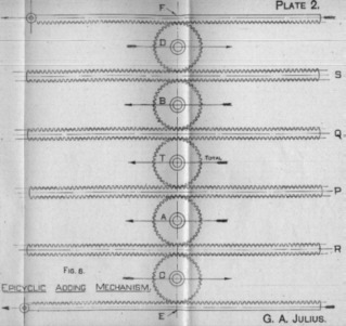
In describing this gear, reference will only be made to the process of " addition," but it is obvious that the gear is equally applicable to subtraction. The gear, as shown, is arranged to receive and add records from six operators, and to show the total upon the total wheel marked " T," by rolling this total wheel towards the left, as shown by the arrow.
For convenience let it be assumed that a movement of the wheel "T" of 1/4 inch to the left represents the issue of one ticket. The six selling machines are connected to the wheels "A," "B," "C," and "D," and to the racks "E" and "F" respectively. The double racks "P," "Q," "R," and "S " are not connected to selling machines, and are merely portion of the adding mechanism.
Suppose the wheel "A" to be connected to a 10s. issuing machine, and to be so arranged that the issue of each 10s. ticket causes it to roll 1/4 inch to the left, as shown by the arrow. If the operator of the selling machine connected to this wheel "A" then issues a ticket, the wheel will travel 1/4 inch to the left, rolling upon the momentarily fixed rack "R," and thereby moving the rack "P" 1/2 inch to the left. The teeth on the upper face of the rack "P" will then obviously cause the total wheel "T" to roll along the momentarily fixed rack " Q," and thus to travel, as a whole, 1/4 inch to the left. It is seen, therefore, that the movement of the wheel "A" 1/4 inch to the left will of itself cause the total wheel " T" to move 1/4 inch in the same direction.
Similarly, if the wheel "B" moves 1/4 inch to the left it will cause the total wheel " T" to move 1/4 inch in the same direction.
Next take the wheel "C." It is so connected to a selling machine that the issue of a 10s. ticket will cause it to move 1/4 inch to the right, as shown by the arrow. If for the moment none of the other issuers are issuing, this movement of "C" of 1/4 inch to the right travelling along the momentarily fixed rack "E" will cause the rack "R" to move 1/2 inch to the right, and this, by reason of the fact that the axis of the wheel "A" is momentarily fixed, will cause the rack "P" to move 1/2 inch to the left, and thus, as before, move the total wheel " T" 1/4 inch to the left, again recording on "T" the sale of a unit ticket. Obvously the operation of the wheel "D" is the same.
Next consider the rack "E" and assume that it be moved whilst all the other issuers are idle. The rack "E" is caused to move 1/2 inch to the left when the ticket issuer connected to it issues a 10s. ticket. This movement will, through the momentarily fixed wheel "C," move "R," 1/2 inch to the right, which again, through the wheel "A," moves "P" 1/2 inch to the left, and this in turn moves the total wheel "T" 1/4 inch to the left. Similarly for the rack "F."
It is thus seen that unit movement of either of the wheels "A" or "B" to the left, or either the wheels "C" or "D" to the right, will move the total wheel "T" through unit movement to the left. It is also seen that a double unit movement of either of the racks "E" or "F" to the left will move the wheel "T" unit movement to the left.
Now let us suppose that two of these movements occur simultaneously by assuming that the two ticket selling machines attached to the wheels "A" and "C" respectively operate at the same instant. The unit movement of the wheel "C" to the right causes a movement of the rack "R" through twice the distance to the right, and this through the wheel "A," if it were fixed would cause the rack "P" to move twice the unit distance to the left. But at the same instant the centre of the wheel "A" is moved unit distance to the left, and obviously, therefore, the resultant movement of the rack "P" is four times unit movement to the left, and this will move the total wheel "T" through two unit distances to the left, and thus record the sale of two tickets.
A little consideration will show that the whole of the six movements may take place simultaneously, and the gear, therefore, is capable of adding the records simultaneously received from six operators.
In the foregoing description it has been assumed that all these wheels are connected to the 10s. issuing machines, but it is obvious that if, for instance, the wheel "B" were connected to a £1 machine, all that is required is to cause the wheel "B" to move through a "two-unit" distance to the left for every £1 ticket issued. Similarly the same argument would apply to £5 tickets, and tickets of higher value.
It is obvious, however that the gear as shown in diagram No. 8 could not be used, because the racks would have to be of impracticable length, and in practice the racks are replaced by bevel wheels. The various records are then made by the rotation of the wheels A, B, C, D, and hence T about their axes, instead of by the lateral translation of these axes.
This arrangement is shown in Figure 9 (the corresponding parts in the arrangement shown in Figures 7 and 8 being "lettered" the same), and its operation should readily be followed, it being merely necessary to change the motion of translation of the gears shown Figure 8 to one of rotation of the gears shown on Figure 9.
Figure 9 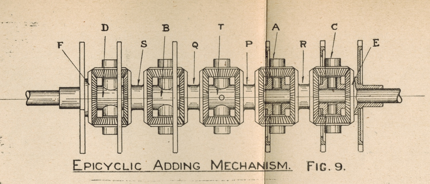
At this point a number of difficulties arise. Firstly, it would be manifestly impossible to accurately rotate these gears by means of the impulses received from the ticket-selling machines. Not only would the power required be excessive and the mechanism very complicated, but the "backlash" in a train of gears such as that described would give rise to endless inaccuracies. "Power" has therefore to be applied to move the gears, and to be so arranged that the issue of tickets on the various ticket issuers controls the extent of the movement.
In the earlier machines the counters or numerators were driven by heavy weights, and these weights also acted upon the train of epicyclic gears, causing these gears to move when they were allowed to do so by the sending of the records through from the ticket issuers. This arrangement, however, gave rise to great difficulties, and was found to be only applicable to relatively small machines. It has, in fact, since been entirely abandoned for all types. It will be remembered that the rate at which the counters would be required to "record" if direct connected to the ticket-selling machine might vary from "nothing" at one instant to a rate of several thousands a minute at the next instant, and it is impracticable to construct counter wheels 2 feet in diameter to stand such treatment.
The epicyclic gears, however, must obviously respond instantly to the records transmitted through them. Thus, if fifty clerks simultaneously issue tickets on the same horse, the records of those sales must instantly be picked up by the epicyclic gears, and as the large counter wheels cannot instantly respond to this demand some form of "storage" gear has to be introduced between the epicyclic gears and the counters to "store" up the records until the counters can he brought up to the necessary speed to record the sales. But this alone would not be sufficient, because if a form of storage gear was put in to merely allow the counter to get up to speed, then if at one instant tickets were passing at the rate of, say, 2,000 a minute on a horse, and at the next instant the issue of tickets ceased, the counters would work up to their speed of 2,000 a minute, and then required to stop dead when running at top speed. Such an arrangement would be obviously impracticable, and the goal has therefore to be so designed as to allow of, firstly, the instantaneous response of the epicyclic gear to the demands made upon it; secondly, the storage of these impulses during such time as the speed of the counters is being brought up to meet the requirements; and, thirdly, the gradual slowing down of the counter as it overtakes the registration of the stored-up records.
In other words, the mechanism that stores up the records has to control a variable speed gear, which will as required gradually speed up or gradually retard the counters, and so avoid all shock to the mechanism.
In the original designs the issue of all tickets of every denomination whether 10s., £1, £5, or £10, were transmitted to the unit wheel of the counters or numerators. This, however necessitated a very high speed of operation for the unit wheel, because although each unit bet only required one-tenth of a revolution of this wheel, each £10 ticket required two complete revolutions and in a machine of this type and of relatively small capacity, the speed of the unit wheel frequently reached speeds as high as 200 revolutions a minute. As it was obvious also that tickets of a denomination higher than £10 would be required, and even possibly as high as £1000 it was apparent that the practice of passing all registrations through the unit wheel would have to be abandoned.
In the latest type, therefore, only the 10s. and £1 registrations pass through the unit wheel. The £5 and £10 registrations are passed direct to the 10's wheels, the £50 and £100 direct to the 100's wheel, and so on. This, again, required some special design, because the 10's wheel had to record not only the 10's carried forward from the additions of records from the 10s. and £1 issuers, but also had to register the direct issue of £5 and £10 tickets, and similarly for the 100's wheel.
It will also be remembered that in describing mechanical systems of numeration, it was pointed out that the only satisfactory form of counter was one in which the various wheels moved instantaneously to the required position. Thus the 10's wheel would be required to move one division at the instant that the, unit wheel moved from 9 to 0.
With counter wheels of 18 inches or 2 feet diameter, and with a unit wheel revolving at a high speed, it is impossible to make the units wheel pick up and move the 10's wheel forward at the right instant without excessive shock, and in all these large high-speed counters, therefore, the 10's wheel has to be operated by, "relay " controlled by the movement of the unit wheel, but so designed that the 10's wheel and the wheels of higher denomination move forward without shock. The foregoing conditions have been met, in the following way :-
An Electro Mechanical Shaft Adder circa 1926 not part of George's paper
The epicyclic gears are made as light as possible, and are urged forward by " coil springs " and not by "weights." This ensured the instantaneous response of the epicyclic gears to the demands of the ticket-sellers. The movement of these gears so obtained is transferred to a " storage " screw which serves two functions, firstly, that when the machine is at rest it locks the driving gear which operates the counter wheels, and, secondly that when issues are to be recorded, it stores-up the records until they are registered by the counters. Immediately the tickets are issued the epicyclic gears instantly operate, being driven by the coil spring, and in so doing they turn the screw which then unlocks the driving gear for the counter, and the counter begins to operate. In so operating, this driving gear also moves a nut, which, acting on the storage screw, tends to bring it back to its normal position of rest, and thus again lock the counter driving mechanism. Thus the epicyclic gears in picking up impulses received from the ticket-sellers move the screw backwards, and the, driving gear of the counter is always trying to overtake this movement and thus return the screw to its normal position.
The movement of this screw is so arranged that it also controls a variable speed friction gear through which the counters are driven. During any period of acceleration in the issue of tickets, the screw is withdrawn in the nut faster than the counter operates, and this through the friction gear speeds up the counter, and the nut, in an endeavour to overtake the movement of the screw, and a condition of balance is ultimately established. If the issue of tickets is retarded or ceases, the nut immediately gains on the screw and brings it forward, thereby picking up all the stored-up records, and by means of the friction gear gradually slowing down the counter until when all the records are recorded, it quietly comes to rest. The rotation of the nut also is utilised to continually rewind the coil spring which operates the epicyclic gears, and thus ensure a steady driving effort on these gears.
The whole operation is entirely automatic and the speed is adjusted to suit the requirements of the ticket issuing. The arrangement of gears, screw, and nut is shown diagrammatically in Figure No. 10, and in more detail in Figure No. 11.
Figure 10 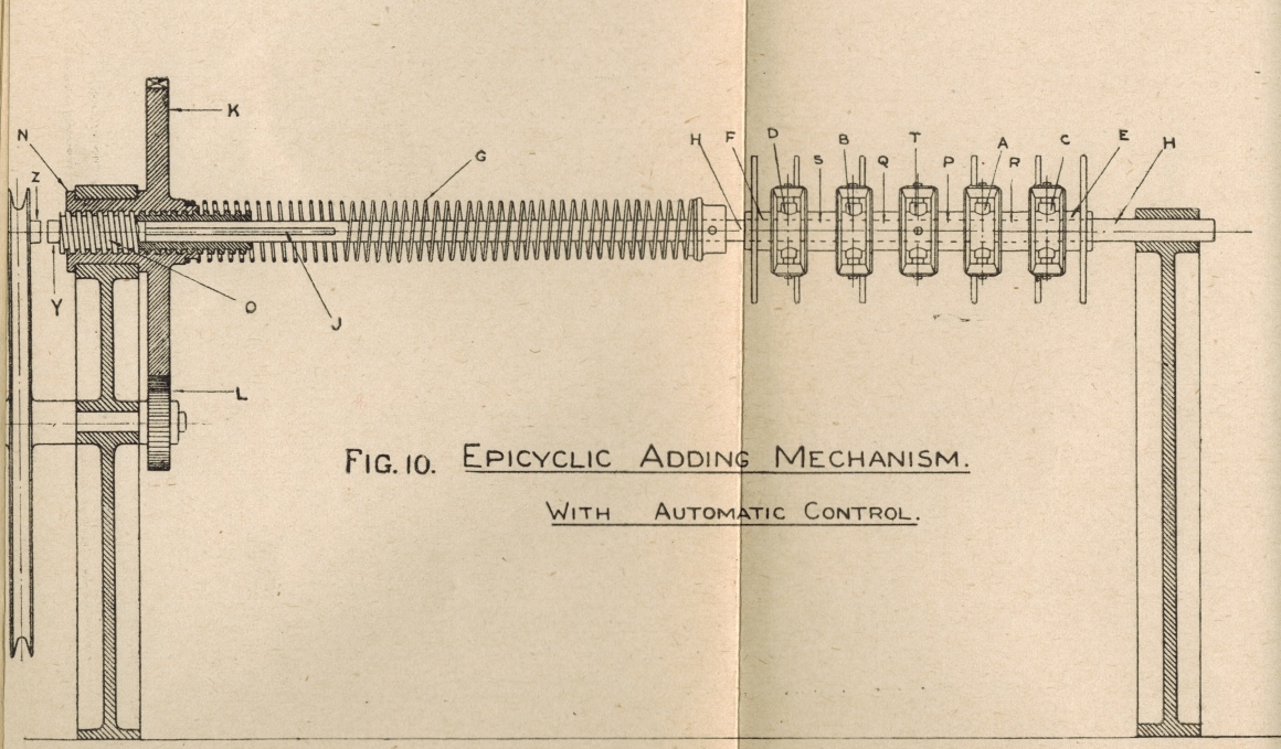
 Go back to the index
Go to the bottom of the page
Go back to the index
Go to the bottom of the page
Epicyclic Adding Mechanism
Figure 11 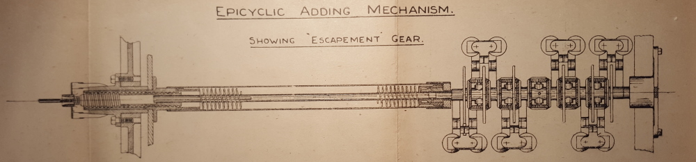
It will be remembered that the extent of the movement of the epicyclic gear has to be controlled by the value of the ticket issued.
Webmasters Notes:
I think a little explanation and relating of Figure 11 above to what George has written is warranted. To the right of the right hand crease, in the plan view drawing Figure 11 above, is a small section of the long tubular storage screw, which connects to an adder on its right hand side. This adder contains the epicyclic gears that George repeatedly refers to. A closer view of the adder's adding shaft with its epicyclic gears is seen in Figure 9 above. The adding shaft in Figure 11 consists of the horizontal shaft segments that make it look like a continuous shaft passing through the Adder, attaching on the left hand side to the Storage Screw body and on the right hand side ending attached to a wheel. Six solenoids with dual electromagnet coils drawn as pairs of circles can be seen in Figure 11, three above the adding shaft and another three below forming the upper and lower limits of the adder part of the drawing. There are six escapement wheels visible which are the six tall narrow oblong rectangles perpendicular to the adding shaft and aligned with the gap between their respective solenoid coil pairs. Above each electromagnet coil pair where the coils are closest to each other, the armature of the solenoid can be seen. These are the stubby T shaped objects with two + marks at their horizontal extremities seen sitting on top of each coil pair. The vertical part of the T for the top three solenoids and inverted T for the bottom three solenoids can be seen in Figure 11 extending towards their associated escapement wheel. Each of these metal armatures is pulled towards its associated coil pair activating its associated escapement mechanism, when current flows through its associated coils to allow the escapement wheels to rotate one tooth at a time when recording bets. An escapement wheel, solenoid and escapement mechanism can be seen in figure 12 below. Five epicyclic gear arrangements are also visible on the adding shaft in Figure 11 above, each consisting of two horizontally oriented and two vertically oriented bevel gears looking like rectangular boxes, required to sum the rotation of the six escapement wheels. This summing process begins at the far left and far right escapement wheels on the adding shaft and the epicyclic gears cumulatively sum the rotation of these outside escapement wheels with those along the way to the centre. As can be seen the centre epicyclic gear has no associated escapement wheel. It sums the left hand adding shaft segment total rotation with the right hand segment total rotation. It receives the sum of the rotation of the left hand escapement wheels on its left bevel gear and the sum of the rotation of the right hand escapement wheels on its right bevel gear. The sum of the left and right hand bevel gears is represented by the rotation of the axle of the upper and lower bevel gears of the centre epicyclic gear around the adding shaft. The dot like small circle in the centre of the centre bevel gear shown in Figure 11 above, indicates that this rotation of the vertically oriented axle of the epicyclic gear around the adding shaft, drives the internal output shaft that extends out of the left hand end of the adding shaft and is connected to the rod that drives the internal screw inside the tubular section of the Storage Screw body. The tubular storage screw body then runs left past the crease in the drawing and extends slightly past the second crease on the left hand side. The vertical mechanism, perpendicular to and near the left hand end of the storage screw is the drive pulley which provides the motive force for the Storage Screw and the Adding Shaft. The thin rod projecting from the left hand end of the storage screw tube is part of the internal screw position sensing mechanism that drives what George calls the variable speed friction gear. This slows the inertia limited part of the system down when the storage screw is in the vicinity of its rest position, accommodating the inertia and bringing the higher inertia parts to a gentle stop, reducing mechanical stress to a tolerable level and ultimately locks the storage screw unwinding section or nut, keeping it from moving when the screw is in its rest position. The mentioned Internal Screw can be seen in its rest position at the left hand end of and inside the tubular body of the Storage Screw. The Internal Screw extends right from the right hand end of the thin rod projecting out of the left hand end of the Storage Screw body, through the pulley and furhter right to a position where the Internal Screw Driving Rod, that can be seen running through most of the centre of the Storage Screw Body, enters the right hand side of the body of the Internal Screw.In George's time there is no evidence that I can see, that the storage screw was considered to be a form of memory. Having spent a working lifetime in electronics and computer engineering, I clearly recognise the storage screw as being a mechanical counterpart to what in computer terms is called a buffer memory. One connection between these two concepts is recognisable in George's naming of this device Storage. I suspect that this may be the first use of the word Storage to imply memory. Computer technologists will recognise storage as an essential aspect of digital computer design. So in modern terminology when the storage screw is in its rest position, it can be considered that the buffer memory is empty. Simplistically, the principle of this mechanical memory is that the amount the screw is wound into the body of the storage screw, is the same as the amount it has to be wound out until it returns to its point of origin and that is how the storage screw fulfils its memory function. Unlike our normal perspective of a screw and nut however, winding in and winding out of the storage screw for the most part is done simultaneously. Having mentioned this analogy I will go further and draw another one. The sensing of the position of the storage screw inside the nut and the feedback path controlling the rotational velocity of the nut or unwinding section of the storage screw, as a function of the screw position is what in the electronics age would be called a closed loop servo system. As can be seen in Figure 10 George terms this Automatic Control. Now back to George's paper:
Each epicyclic gear has attached to it an escapement wheel mounted concentric with it, this wheel being very similar to the ordinary escapement wheel in a clock. These escapement wheels are themselves controlled by "dead-beat" escapements which are electro-magnetically operated from the ticket-selling machines. One such group is shown in Figure 12.
Figure 12 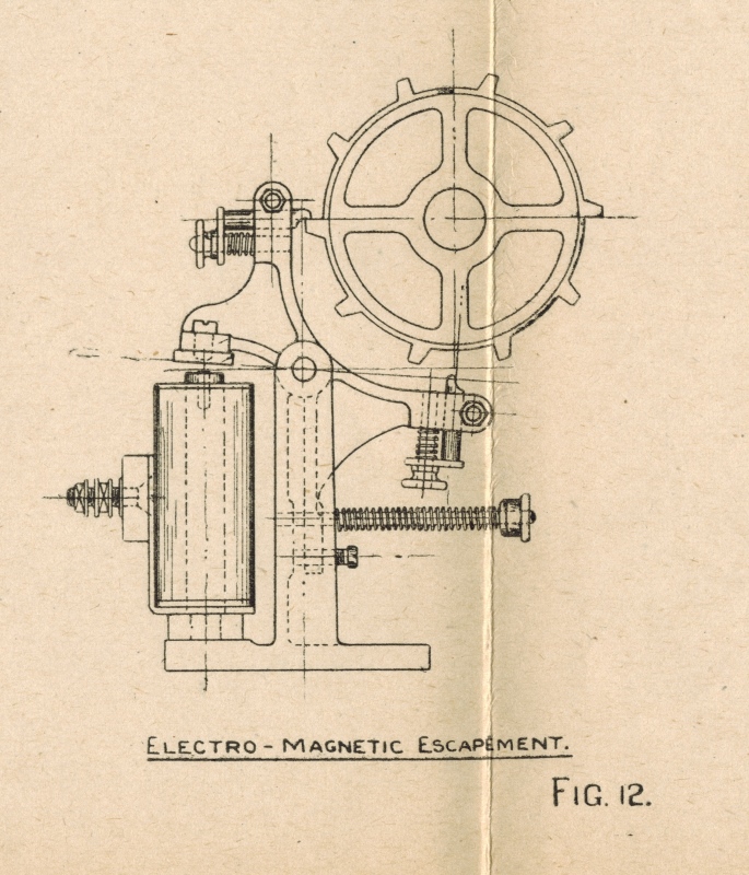
When a ticket is issued, an electrical impulse is sent through from the ticket-issuing machine, which, operating the correct escapement, allows the particular escapement wheel and the epicyclic gear attached thereto to be moved forward one tooth, the driving force being the coil spring. By varying the number of teeth on the escapement wheels the amount of rotation that accompanies the issue of any particular ticket can be varied. Thus if the movement of one tooth of a " twenty-tooth " escapement wheel is arranged to record the sale of a 10s. ticket, then one tooth on a "ten-tooth" escapement wheel will accurately record the sale of a £1 ticket.
Until recently the adding gear has comprised an electromagnetic escapement and a corresponding epicyclic gear for each ticket-issuing machine; thus, on the large machine installed at Randwick there are forty selling-machines and the adding gear of each horse counter or numerator comprises forty sets of escapements and epicyclic gears arranged in four groups of ten. A central gear on each group of ten gives the added results of the issue of the ten selling windows, and these four sets of added results are again combined to give the sum total of the issues of the forty selling machines.
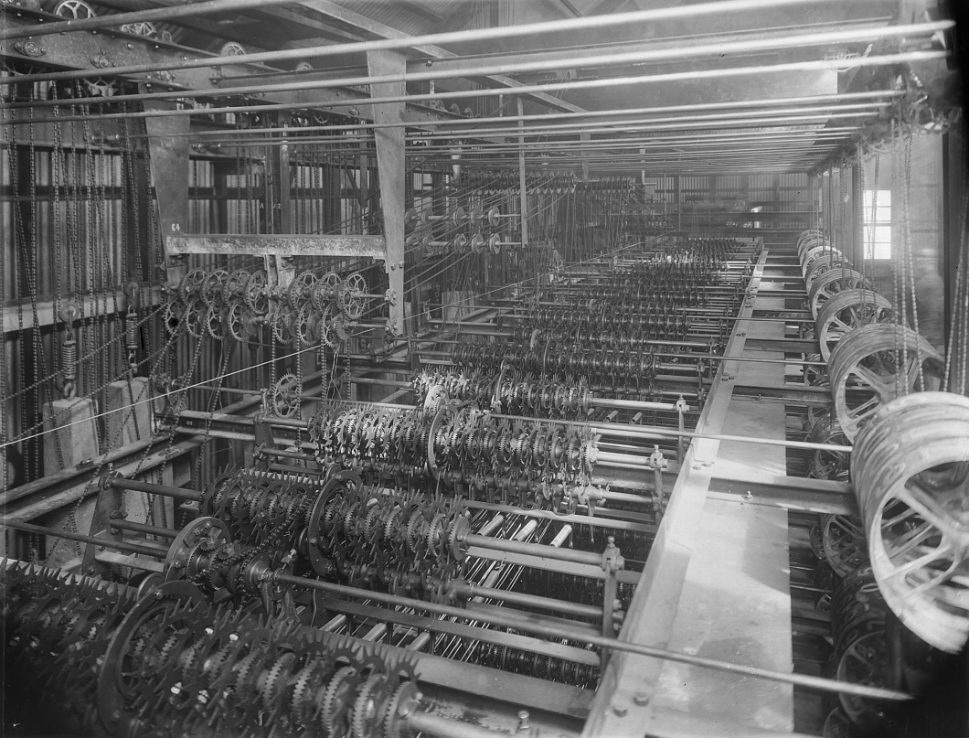
An adder from the Randwick Tote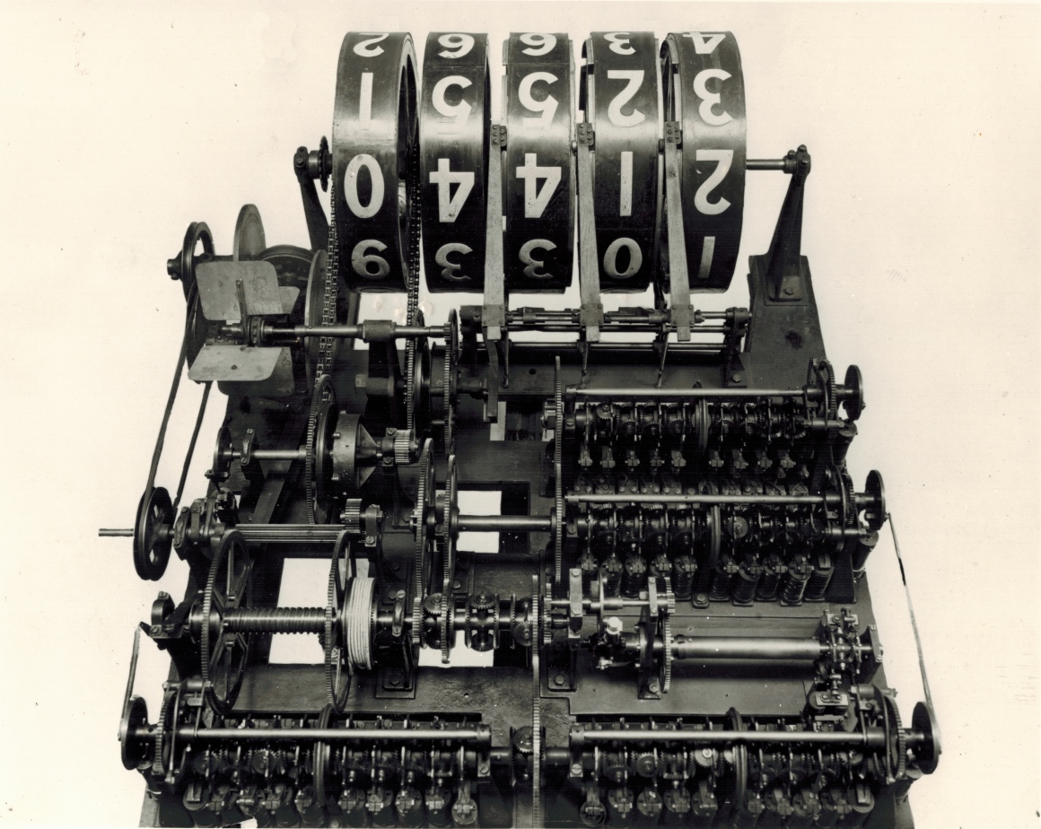
The image above and the following text is not part of George's paper.
The image above shows one of the adders that belonged to what George refers to as the large machine installed at Randwick in the previous paragraph, which he calls a horse counter or numerator. The forty sets of escapements and epicyclic gears arranged in four groups of ten which George mentions are clearly visible in this image. Two of these groups of ten adding shafts run along the complete front of the adder at the bottom of the image. Two more of these shafts can be seen one behind the other on the right hand half of the adder towards the rear near the large counter wheel display drum.It is obvious however, that there is a practical limit to the number of epicyclic gears that can be grouped together in one train. The driving force is applied to the gear at the middle of the train, and there is a loss through friction in each set of gears; too long a "train," therefore, would result in an undesirably great discrepancy between the driving force on gears at the centre of the train and that on gears at the end of the train. Seventeen sets of gear have been grouped together and have operated successfully, but experience has shown that it is undesirable to exceed ten in a group.George refers to the sum total. The central gears that George mentions, of the two front adding shafts, drive an epicyclic gear in between the two shafts, which sums the angular displacement of these two shafts and the associated cog of this epicyclic gear transfers this rotation to a short adding shaft behind the front ones, in the second row of equipment.
The central gear of the two right hand rear adding shafts, are summed at the cogs on the left hand side of these shafts and this rotation is transferred to cogs on the left hand side of the adder via a short shaft extending left from the near side adding shaft. From there this angular displacement is transferred to the previously mentioned short adding shaft in the second row of equipment.
The short adding shaft sums the rotation of the two groups of two adding shafts and applies it to the Storage Screw to the left which looks like a square threaded shaft between two large cog wheels on the far left of the adder in the second row of equipment. George has referred to the Storage Screws above and I have added my contemporary view of them above Figure 12 in the Webmasters Notes, so I will leave it at that and proceed with George's paper:
In considering the application of the equipment to meet very much greater demands, it was apparent that the very large amount of gearing required under what may be called the Randwick system would be very costly both to install and to maintain. A modification of the system has therefore been developed, and may be briefly described as follows :-
In practice each issuing machine should be run at such a speed as will allow of the printing and issuing of tickets at the rate of 100 per minute, this being the maximum speed required. It has been found, however, that the electro-magnetic escapements can be installed to accurately pick up and record impulses at more than ten times this speed. The latest machines have therefore been constructed with one electro-magnetic escapement and epicyclic gear for each eight or ten ticket issuers. In this arrangement, however, allowance has to be made for the fact that the ten-ticket issuers may all issue tickets simultaneously on the same horse. Each issuing machine therefore is equipped with a device which stores up the impulse as soon as the machine starts to print a ticket, and this stored-up impulse is picked up by a distributor and passed on to the electro-magnet at a, speed that is slightly greater than the maximum speed of the issuing machines. Thus, if the ten issuing machines simultaneously start to issue a ticket on the same horse, during the issue of these tickets, the distributor picks up the ten impulses and delivers them in sequence to the electro-magnetic escapements. In such a case the electro-magnetic escapement would make ten beats in the time occupied by a selling machine in printing and issuing one ticket.
This modification has very greatly reduced the amount of adding gear required in the machine, as in the new type four, or at most six, escapements perform the same duty as was previously performed by the forty escapements in the Randwick type of machine.
This becomes of great importance in considering large equipments. A unit has recently been built to meet the conditions of betting on the largest French racecourses. On such courses it is necessary to allow for the installation of at least 600 selling machines, and the counters may be required to record the issue of a million tickets in half an hour.
The unit that has been designed and built will pick up the impulses from 900 windows selling tickets of various values between 10s. and £1000 and will add these impulses and record them at speeds up to 250,000 a minute; that is, at a rate exceeding 4,000 per second. Such a speed is in excess of anything that can conceivably be required, but it must be remembered that although the issue of a million tickets in half an hour calls, for an average speed of issue of approximately 33,000 a minute, yet the issue of tickets is not uniform, and double this speed may be required during any particular minute.
Where installations of this magnitude are required, it is obvious that groups of selling machines have to be installed at various points on the racecourse, as it is impossible to bring the crowd to one spot. It is essential, then, that the crowd located at one group of selling machines should be kept informed of the state of the betting all over the course. In such cases, therefore, the impulses from the selling machines all over the course are transmitted to a central calculating equipment, this central equipment controls the operations of a number of indicators which may be located in any convenient positions, one set being placed near each group of selling machines. Thus, in an equipment to sell tickets on any of forty-two horses from 900 selling, booths, there would be 900 individual selling machines divided up into, say, twenty groups of forty-five in each group. There would also be forty-two central calculating units, one for each horse, and a grand total calculating unit. These in turn would control twenty groups of indicators, each group comprising forty-two indicators, one for each horse, and a grand total indicator. The whole installation therefore would consist of 900 printing and selling machines, forty-three calculating units, and 860 indicator units , the whole system being automatically controlled and, operated by the issue of tickets from the 900 selling machines. A unit of this capacity has, as before stated, been built, and thoroughly tested , and is available here for inspection by members.
Central Calculating units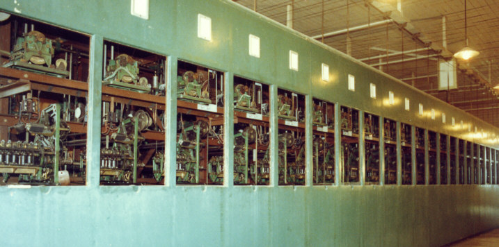
The above image is not part of George's paper but is a 1940s Julius Tote at Eagle Farm racecourse, in which the calculating units that George refers to above can be seen, one in each window of the mainframe.
Although the ticket issuing and printing machines are now considered to be a fundamental portion of the whole totalisator equipment, yet they are not directly concerned with the adding mechanism, and will therefore not be further described. An equipment, however is available here for inspection.
As previously mentioned, the whole installation has to be so designed as to efficiently guard against the effect of faulty manipulation or accident. Each calculating unit, therefore, is provided with gear which instantly locks all the ticket issuers connected to that unit should the electric power fail, or the driving power for the counters break down, or also should any essential belt or spring: break.
The gear is so arranged that a breakdown of the calculating mechanism that is recording the issue of tickets on any horse only locks the ticket-selling machines against a further issue of tickets on that; particular horse, and does not interfere with the issue of tickets on other horses. If the breakdown is merely temporary, repairs would be effected, and the calculating " unit" thrown into operation again. If it were serious the " unit " would be cut out of operation, and a spare " unit" thrown into gear in place of it. It may be mentioned, however, that in seven years experience of these machines it has never yet been found necessary to throw a calculating unit out of operation.
It has only been possible for the writer to describe the leading features of these machines, but he hopes that the various working models that are here available for inspection will enable members to fill in the missing details, and to more fully understand the operation of the equipments.
| How the Automatic Totalisator was invented |
1932 'HOW THE AUTOMATIC TOTALISATOR WAS INVENTED', Gippsland Times (Vic. : 1861 - 1954), 7 January, p. 3. , viewed 20 May 2016, http://nla.gov.au/nla.news-article62691937
HOW THE AUTOMATIC TOTALISATOR WAS INVENTED
------------:0:------------
From the Blackboard to the Machine.
------------
(By Sir George Julius).
------------
It has been suggested to me that the public might be interested to know something of the various developments that have led up to the production of the totalisator recently put into operation in Melbourne. I have been asked also to go back some years to give some personal history of my earlier training and the factors that led up to the interest I have always taken in mechanical contrivances.
Any inventive capacity I may have may be attributed to inheritance through two generations. My father--formerly Archbishop of New Zealand--inherited his love for mechanism from his father, who was one of the Court physicians in London, but had such a mechanical bent that he spent what money he had in backing any invention that had wheels in it.
I entered Melbourne Grammar School in 1885. After matriculating here at the University I entered the New Zealand University--where one of my fellow students was the now eminent physicist, Lord Rutherford--and was its first graduate of engineering. After specialising for two and a half years, particularly in railway engineering, I went over to West Australia during the height of the gold boom of the 'nineties, and secured an engineering position in the Government railways which I held for 11 years.
A friend in the West conceived the idea of getting me to make a machine to register votes, and so to expedite elections. I invented one that aroused some interest, and it was submitted to the Commonwealth Government. It had been urged, however, to adopt the Hare-Spence system. I then produced another machine which would register only when an elector had voted formally, which automatically recorded preferences, informed the returning officer if the vote was informal, and gave the result without any human intervention, being purely mechanical. But by that time the Government had changed its mind again, and wanted another system. I was so discouraged that I broke up my machine, in disgust and abandoned further attempts.
Up to that time I had never seen a racecourse. A friend who knew of a "jam tin" tote--a machine which kept a sort of record of tickets sold at each window--explained to me what was required in an efficient totalisator. I found the problem of great interest as the perfect tote must have mechanism capable of adding the records from a number of operators all of whom might issue a ticket on the same horse at the same instant.
There was a machine, originated by an Australian named Gabriel, who got over the difficulty by liberating a number of steel marbles all running along channels, ultimately meeting at a counter and as they flowed through the counter, operated the mechanism to register the sales.
Early Difficulties in New Zealand
Experience showed that there was a definite limit to the value of the machine in regard to capacity, as the marble mechanism was not suited for very large racecourses.
I set to work on a machine that would permit of simultaneous addition, give instantaneous records, and would satisfy the requirements of any racecourse. The model was built in my spare time, and as the result a company was formed and secured its first order for a machine at the Auckland racecourse in 1913. That was my first tote.
The world's first automatic totalisator
Webmaster's note: Sir George refers to a model being built in his spare time. This totalisator model is at the time of writing, 2016 in the Powerhouse Museum in Sydney. Matthew Connell the Principal Curator of the Powerhouse Museum refers to this as the "Jewel in the Crown" of the Powerhouse Museum's collection.
Today I am horrified when I contemplate the atrocities I perpetrated in that first machine. This machine was followed by another in 1916 ordered by the Trotting Association in Perth. These were entirely mechanical, as I had the idea that if electric current were employed definite action could not be guaranteed due to the permissive action of electricity as compared with positive action of a piece of machinery.
I soon discovered, however, that a design restricted to the use of positive mechanism would cripple development, as the machinery was very heavy and all the recording had to be centred at one spot. Attention was then directed to a machine in which electricity would be the connecting medium, but with safeguards to ensure that if there were any failure, the operator would be warned, and the ticket not issued.
Somewhat earlier--in 1916---I had come to the conclusion that success would be facilitated if the machine could print the tickets as they were sold, and that the act of printing should give the impetus to the recording mechanism. I then produced a ticket-issuing machine, which printed the number of a horse and other information, but the connection with the recording mechanism was by means of a complicated series of steel wires.
George's ticket-issuing machine
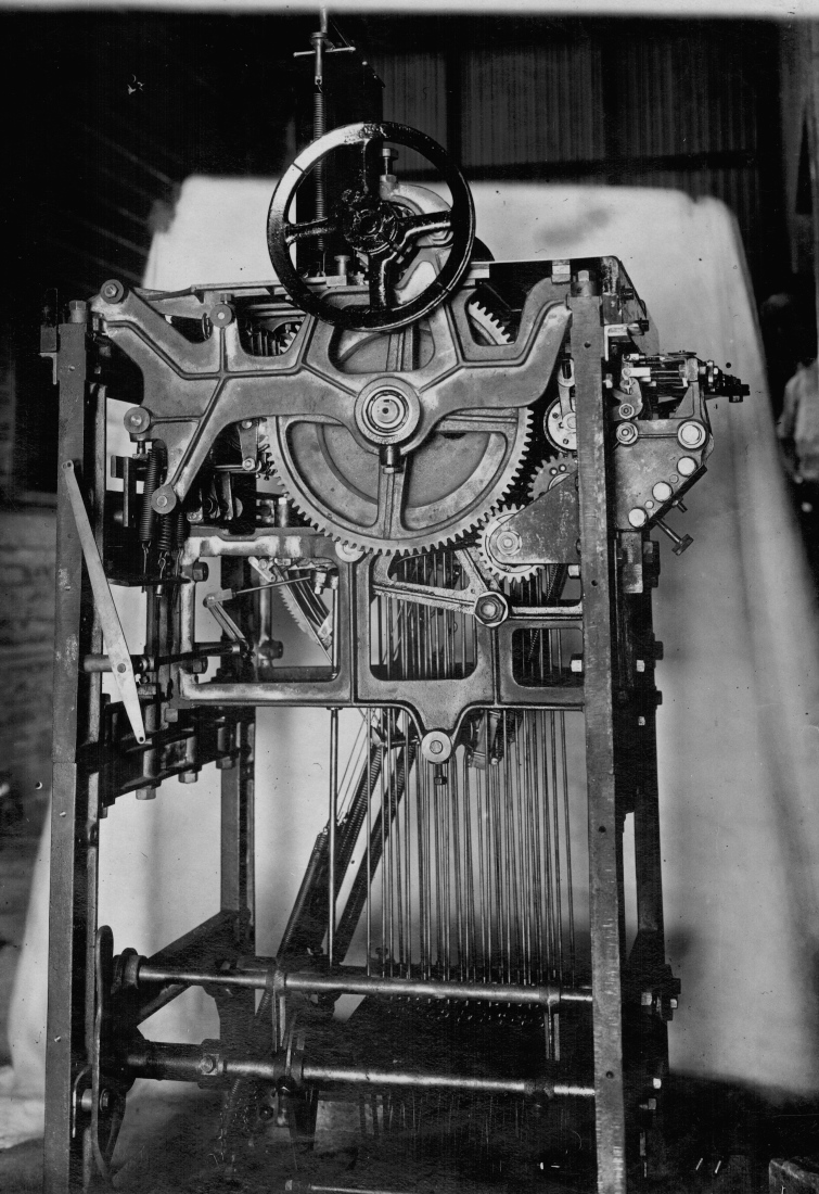
Webmaster's note: This is the machine Sir George refers to in the previous paragraph, with the connection to the recording mechanism being via a complicated series of steel wires. Being the first, it was designated the name J1. It is shown with its covers removed.
In 1917 I re-designed this equipment and the act of printing the tickets from blank rolls of paper transmitted the record of the sale of the ticket to the adding machine, by means of electricity. There were also safeguards, so that, if there were any interruption between the selling machine and the tote, the printing machine could not print the ticket. That system, but much improved, is in use to-day.
It was in New Zealand that a first attempt was made to inform the public of the investments on the machine by stationing men with blackboards behind the sellers. The men chalked up the records of sales and passed them on to others who operated manually a series of counters to indicate the progress of the betting. But while this was a great improvement on the blind tote the record was always posted much behind the time of the betting--so much so that the wheels would be still revolving when the race was finished.
This led the New Zealand Government to prohibit the starting of a race till the tote wheels had stopped, as dishonest people could otherwise gain an advantage. This legislation, of course, was followed by hopeless delays to the starts of the races, the horses sometimes having to wait 20 minutes at the barrier, and in some cases thus lost any chance of winning.
Obviously, if this difficulty were to be overcome it was necessary to produce an automatic recorder which would record and indicate the sale of tickets practically instantaneously, so that at the completion of selling, the record of sales would also be complete. It was upon the production of such a totalisator, with printing machines associated therewith, that I concentrated for many years, and, with the exception of the new machines now being erected in Melbourne, and of four small ones recently sent to England, there are no totes in the world which do more than record instantaneously the number of tickets sold on each horse, and the grand total of the investments.
In recent years, however, and particularly after a visit to England, I came to the conclusion that the perfect tote should do more than indicate the number of tickets sold, as by stopping the recording at that spot, it left the investor to calculate from the numbers what dividend he was likely to get.
Recently I have been able to add to the original patents further mechanism, which is very simple in detail, and which picks up the records of the number of tickets sold, deducts the Government tax and club percentage, and, continually divides the pool so obtained by the number of tickets sold on each horse.
This makes it possible to indicate to the public the odds on any runner at an instant during the betting, and so relieves the investor of the necessity of making any calculations.
These machines have all been built in Australia in almost every detail, and are a tribute to the abilities of the Australian workman.
![]()
As you have read this far, you will probably be interested in having a look at some video clips from Andrew Keene's excellent video of a working Julius totalisator.
Additionally, if you are interested in the Storage Screw devices, you can read about them described with reference to their implementation in the adders used in the Bombay system at Western India Turf Club Adder and Indicator Unit and Shaft Adder - Electromechanical Computring as well as this adder used in Longchamps Paris One of the many large Adders at Longchamps.
Finally, if you are interested in the shaft adders, as before you can read more about them described with reference to their implementation at A historic 3 shaft adder used in Julius Totes.
| Acknowledgements |
Comments and suggestions welcome to
totehis@hotmail.com 
| Previous page | Go to the index | Top of the page | Next page |