This is one of several history only, non commercial, pages relating to the history of the automatic totalizator, its invention in 1913, the inventor George Julius and the Australian company he founded in 1917 which became a monopoly, later part of an oligopoly, in this field. This page contains a document written in 1930 regarding the operation of a Premier electro-mechanical totalizator. Premier is the name George gave to his product and it is also commonly known as the Julius Tote. This page also contains a transcription of a talk given by Neville Mitchell, the best Automatic Totalisators Limited historian I know, about this system.
Copyright © 1997 Email - totehis@hotmail.com
| The Premier automatic totalizator operation 1930 |
|---|
| Simplicity of Operation |
The machine has excited the wonder and admiration of every body who has watched it operate. It all seems so absurdly simple. As fast as money is poured through the windows for investment on various horses in a race just so fast each new amount is recorded in full view of everybody, on each horse, and at the same moment the grand total of the investments on the race is brought right up-to-date. Each separate operation is completed with the speed of thought. The clerk is pressing a tiny lever to release the ticket which acknowledges the transaction by the same simple act registers it. Nothing could be quicker or more simple. It is all so much easier for investors than rushing about among the excited crowd which gather around the book makers' stands. There is no bustle, no crowding, no argument, just a business transaction done without fuss or bother.
Is it any wonder then that the racing public appreciate the Premier totalizator and that it is constantly being installed in new centres?
| The Premier totalizator explained |
The totalizator records the total sales from instant to instant on each horse, and also at the same time, the grand total of the sales on all horses. Usually and preferably, it is installed to record the equivalent number of tickets of the lowest denominations; thus, if the machine is to be operated to record sales of, say, 10/-, 1 pound 5 pounds and 10 pounds, then each 10/- ticket sold adds one to the total recorded on the particular horse, and, at the same instant, one to the grand total. Similarly, each 1 pound ticket sold, automatically adds two to the horse counter and to the grand total, each 5 pound ticket adds 10 to the horse register and the grand total, and each 10 pound ticket adds 20.
The machine can be installed to record the sales of tickets of any value, but the lowest ticket of high value, such as the 5 pound ticket in the above example, should be 10 times, or a multiple of 10 times the unit ticket, that is, the ticket of lowest value; e.g., one 5 pound ticket equals ten 10/- tickets.
The recording mechanism can be constructed with four drums, to read up to a maximum of 9999 on each horse, five drums to, read 99,999, or more, to meet the requirements of the betting.
The whole machine is automatic in operation, being controlled entirely by the issue of tickets, there being no human element between the "issue" of the tickets and the "recording" of such "issue". Further, also, the machine is capable of instantly recording all sales on any horse, even if the whole of the selling windows or the ticket-issuing machines happen to issue tickets on the same horse at the same instant.
There is no time limitation in the operation of the ticket issuers, that is to say, a ticket can be issued from any ticket-issuing machine at any instant on any horse, and its sale recorded on the horse counter and on the grand total, quite irrespective of what may be happening on all other ticket-issuing machines.
In order that the various horse counters and the grand-total counter in the totalizator may be capable of quickly recording sales, no matter whether the majority of the sales are on one horse or divided amongst a number, each recording counter is equipped with a variable speed gear, controlled by a relay device, which automatically adjusts itself to the speed of betting, thereby getting over the difficulty of sudden stopping or starting of the large counter wheels, and thus ensuring that each counter can meet the demands of the betting quietly, and without shock, within the limits of the speeds for which it has been designed and installed.
The smallest machines will allow of the recording of unit bets up to a rate of l000 a minute on any horse, and machines can be installed to allow of betting up to 200,000 a minute on any horse, or even more, should such be required.
A machine has been manufactured and shown in Sydney that records bets up to 250,000 per minute.
The mechanism is so arranged that unit tickets, that is, 10/- and 1 pound tickets, are recorded on the unit wheel of each counter, transferring to the 10s, 100s and 1000's drums, etc., in the ordinary way as required. The 5 pound tickets are registered direct on the 10s wheel of the counters, but such registration interferes in no way with the transmission of bets from the unit drum to the 10's drum, and so on.
Similarly, if the machine is equipped with a ticket-issuing machine for the sale of 50 Pound tickets, that is, of tickets equal to 100 unit tickets, the sale of such is recorded direct on the 100's drum of each counter, without in any way interfering with the correct registration of the 100s coming forward from the sale of tickets of lower denominations.
To allow of the gradual acceleration and retardation of the counter wheels to meet the demands of the betting, each counter is equipped with a storage or "balancer" arrangement which stores up the record of the issue of tickets to a pre-determined limit, thus allowing time for the counter to be accelerated up to the required speed, and thus also allowing the machine automatically to come quietly to rest when betting has stopped, the gear being so arranged that all bets so stored up in the balancer or storage gear are automatically recorded on the counter before it comes to rest.
Assuming that at the time betting ceases any counter was then running at its maximum speed, the time taken to record the whole of the bets then stored up in the mechanism, and to bring the counter to rest, does not exceed ten seconds. The machine may therefore, within the limits of practice, be considered as instantaneous in its action. The ten seconds margin only being required because it would be practically impossible to suddenly accelerate or suddenly stop the counters without excessive shock.
Each counter, as before stated, is capable of receiving impulses from any number of ticket-issuing or selling machines, and such selling machines may be arranged in any way so far as values are concerned, that is to say, there may be any required number of 10/- issuing machines, and, similarly, of 20/-, 5 pounds, 20 pounds, and so on.
Such selling windows may also be located anywhere, as required. They can be placed in the building which contains the totalizator, or may be a mile, or ten miles away. The only limitation to the location of issuers at a distance from the totalizator itself is the question of minimising the amount of electrical wire required. The normal voltage used in all these machines is 110 volts, direct current, and the wire used to connect the selling machines with the totalizator is 1/18, 600 Megohm grade insulated wire.
The group of horse counters and the grand-total counter, which together constitute the totalizator, are driven by one electrical motor, the size of such motor depending upon the size of the installation. This motor in a forty horse equipment is usually about 5-h.p. capacity, and, in a thirty horse equipment 4-h.p. capacity. In very large installations in which the adding machine, or totalizator proper, is located in a special room and not visible to the public, they being kept informed as to the betting by independent recorders at various points on the course, the totalizator would require a 2-h.p. motor and each complete registering equipment a 4-h.p. motor.
| Prevention of Breakdowns |
When this automatic gear comes into operation, it prevents the issue of tickets on that horse only, at all the selling windows, but in no way interferes with the selling and issuing of tickets on any other horse, unless it should have been the driving gear to the grand total which has failed, in which case the sale of tickets at every window on every horse is instantly and automatically stopped.
Whilst in the operation of the many machines of this type which are now in use, this automatic lock has never been called into use, yet it is considered essential to fit each equipment with this gear, so that if, through carelessness or malice or accident, there should be any interruption in the driving power to any counter, then there can be no further issue of tickets on that particular horse until the defect is remedied. Such defect, if it ever occurred, would almost certainly be the breaking of one of the driving belts, and the machine is so designed that any belt can be replaced in five seconds, there being a bell and indicator which at once draws the attention of the totalizator attendant to the fact that there is a stoppage on any particular horse counter.
Beyond the possibility of a failure to the driving belts, there is no, other possible cause of failure, except the complete cutting off of the electrical power supply. The machine is so arranged that such a failure instantly locks the ticket-issuing machine and prevents the further issue of tickets, and all the totalizators on this system which are now running are installed with a "Stand-by" power unit which is always running and which, within two seconds, can be thrown in circuit, thereby limiting the period of stoppage to a maximum period of two seconds, whilst also preventing the sale of tickets during that two seconds, and thereby ensuring the correctness of the records.
The spring gear which operates the electro-magnetic escapements which receive the electrical impulses from the various ticket-issuing machines is so designed as to be entirely out of reach of accidental damage, and the spring itself is arranged to run in an oil bath and to be so lightly loaded that there is no risk of breakage. Even if a break did occur the automatic lock, previously mentioned, would immediately come into operation and instantly stop the sale of tickets and registrations on the particular horse affected. It may be mentioned that in the many machines now operating of this type, there has never been any failure in this driving gear.
The electro-magnetic escapements above referred to, which record the impulses received from the selling machines, are connected to these selling machines by insulated wire, and there is a fuse in each circuit which prevents overloading of any of the electro-magnets.
The machines are so arranged, however, that should there be any interruption in the circuit between any particular issuer, or group of issuers, and any particular horse counter, whether such interruption is caused by the blowing of a fuse, or the breakage of a wire, or the failure of a connection, then such ticket issuer, or group of ticket issuers, are instantly and automatically locked against the sale of any more tickets on that particular horse, and remain so locked until the circuit is put right again.
It must be remembered, however, that as each ticket issuer is capable of issuing tickets upon each and every horse, the failure of a circuit from any issuer to any particular horse would not cause material inconvenience, as it would not in any way interfere with the sale of tickets on that particular horse from any of the other issuers.
The whole of the mechanism of the various horse counters and of the grand-total counter is carefully and strongly built, with ample provision for lubrication and for adjustment, and the parts have very ample strength for the work which they have to perform.
Each counter, with the whole of its mechanism is so designed that it can be attached, by two bolts only, to the front of the building through which the numbers are being exposed, and no elaborate framing of any sort is required.
One line of shaft between the two rows of counters constituting the totalizator serves to operate the whole of the counters and also the grand total, and such line of shaft is driven by one electrical motor of small power, there usually being a second stand-by motor coupled up ready should the first motor fail.
| Official Control |
The counters are so arranged that they can be quickly reset to "zero" after the close of the betting on one race, so as to be ready for the start of the betting on the next race, and the whole of the counters on a totalizator installed to record the betting on forty horses can be re-set to zero by two men within five minutes, and quicker if more men are available.
Each totalizator equipment is controlled by a switchboard adjacent to the machine this switchboard being equipped with the necessary controlling and protective devices, and also with automatic signals, etc., for the guidance of those running the machine as to when to re-set, etc.
Each horse counter is also equipped with a trip switch for cutting that horse out of operation in the event of it being scratched and the circuits are so arranged that when any horse is so cut out, all the ticket-issuing machines are thereby automatically locked against the sale of tickets on that horse, so that, even if such tickets are applied for, they cannot be issued.
| Ticket-Issuing Machines |
 A J8 Ticket Issuing Machine
The operation of each issuer is controlled by a single handle, which, when pressed into a particular hole in a quadrant plate bearing the "number" of the horse for which the ticket is required, thereby correctly places the type, prints and issues the ticket, and records its sale within the issuer itself, and transmits the necessary impulse to the totalizator.
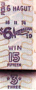
A ticket printed on a J8 ( Animation above )
During the printing operation the handle is automatically locked so that it is impossible for the operator to interfere with the operation of the machine until the then-being-printed ticket is ejected. The type is inked automatically, and the inking process is so arranged that one selected "type" and that "type" only, is inked just prior to the paper passing over it, thus preventing any accumulation of ink on any type, and thereby keeping the whole of the type clean.
The printing gear is also arranged so that the movement of one small handle instantly changes the type which prints the race number on the ticket, so that after the machine has stopped the issue of tickets on one race, such type can be shifted and the paper changed ready for the issue of tickets on the next race, and this change of paper and change of type occupies a maximum of fifteen seconds. The changing of the paper also can be effected at any time during betting should the roll of paper become exhausted, or for any other reason, and such change can be made in five seconds.
The ticket issuers are designed to be power driven with a suitable small electric motor for driving a number of issuers, each issuer taking approximately 1/24th h.p. The machines are so arranged also that should any such motor fail, the machine can be operated by hand without causing any delay, and the issuers are designed so that the operators, that is, those issuing and selling tickets, cannot get access to the mechanism; but, when necessary, any one authorised to do so can completely and quickly expose the whole of the mechanism for lubrication, adjustment or repairs.
The machines are suitable for, operation by one operator who both operates the machine and issues the ticket to the purchaser, or they may be so installed that the machine itself is controlled by one operator, discharging tickets to two sellers, with a suitable deflector, so that the ticket may be delivered to either one of the sellers as required. This is possible because the speed at which the machine will print and issue tickets is considerably more than double the speed at which the public can be handled at any selling window.
Webmaster's note: following are some observations regarding the J8 TIM from Chris Robertson, the most informed punter on the subject of totalisator systems I know. He refers to me not having seen a J8 in operation:
You really missed something there! A house full of J8 machines flat out was something to behold - and to hear. The depressing and release of the issue button had a sound of its own (clackety-clack), and when a whole bank was in action there was plenty of sound. Swinging the machine's dial looked a lot more fun than pushing buttons on the J10.
An interesting place to watch the J8 in action was at Ireland's greyhound tracks. The machines were configured to sell win, place and forecast (exacta) at all windows. This could be done because, as in the U.K., Irish greyhound field sizes were limited to six runners. The first six positions on the dial's arc were occupied by the numbers 1 through 6, and the next fifteen by the various possible combinations, starting with 1-2, 1-3, 1-4, 1-5, 1-6, 2-3, 2-4 and so on. If the customer wanted a forecast with the higher number winning, the button was depressed in the 'place' mode. A boxed combination was sold as an 'each way' bet. I saw the J8 at Cork, Waterford and Dublin's Shelbourne Park; while earlier Julius machines were in action at Dublin's Harold's Cross (as at London's White City). This was way back in 1979.
My J8 Ticket Issuing Machine pamphlet gives the following information regarding pools.
POOLS
The different combinations of pools that can be operated from a J8 Ticket Issuing Machine are:--
| Size and Arrangement of Machines |
There is no practical limit to the size of the equipment, and machines can be supplied to sell tickets at 1000 selling windows, and to record such sales at speeds up to 250,000 unit bets per minute.
| Supervision |
During the meeting two men are required on each totalizator and on each subsidiary recorder, and one mechanic also attends to approximately thirty issuing machines during the betting. Immediately after the close of the meeting the totalizators are wiped down and covered up; the type is removed from the issuing machines, and within an hour after the close of the meeting the whole equipment is cleaned and covered up and does not require further attention or opening up until the day before the next race meeting.
The staff employed in selling and paying operations and dividend calculation is smaller than that employed under "hand" Pari-Mutuel or totalizator system still existing on the Continent of Europe. The Premier totalizator being a hand saving device considerably reduces expenses on labour as well as the time used in all operations.
Does this sound familiar?
| Neville Mitchell's talk on The Premier automatic totalizator |
|---|
Talking about the equipment I saw at Bob Moran's workshop in Mona Vale, very interesting to see an old system like that and the possibility of it being partially restored is an exciting prospect.
I remember how the systems worked, they weren't labour intensive as such, they were very very reliable and much was made out of any malfunction, or any loss of data or even a single unit, the five shilling, or 50 cent bet that went missing on a Saturday afternoon would be thoroughly investigated on the Monday or whenever that particular race track was being prepared for the next race meeting. Often the mistakes were human rather than electromechanical.
| The J8 Ticket Issuing Machine |
I have provided images of a J7 rather than a J8 here, as I have superior photos that show the internals of the J7 better than the J8. As Neville mentions in the previous sentence the principles are similar. There is an animation of a J8 above. The J7 below looks like a well used machine.
A J7 Ticket Issuing Machine (TIM)
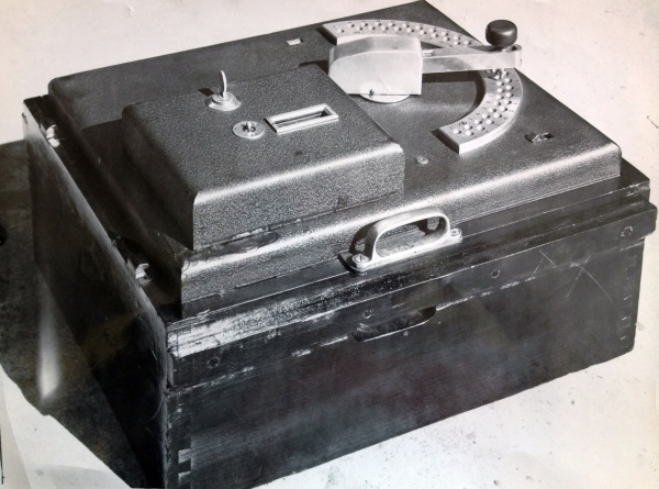
The manufacturing technique had changed, a lot of the machining and delicate parts were now produced by semi-automatic machines. Prior to that they were just manually machined and some of the parts were even made by blacksmiths. They were part of the industry even when I was there in 1962 there was a blacksmith at the Meadowbank plant. The J8 was used all over the world North America Africa all of Australia all over Asia. It was extremely popular robust and highly reliable. It required very little actual maintenance the main maintenance of them was the replacement or re-inking of the print ribbon, the cleaning of the print platen and in tropical areas the control of corrosion was the major maintenance activity with the machine.
The above image of the J7 with the top cover removed reveals the print platen area and shows the print ribbon, as mentioned by Neville, on its reel. I think the disc with 1 to 10 near the perimeter is the race select mechanism. Neville describes this later in this section.
Under ideal conditions and with a properly maintained and nicely tuned mainframe adder, the J8 could produce 90 tickets per minute which was the mean average they could do and this dependent on a fair few things as well as the skill of the operator. I noticed in Melbourne in the 1960s and later that competition between the ticket sellers especially in the smaller totes like in the Owners and Trainers and Bookmakers Tote area and places like that, where there was only three or four ticket sellers and when it was coming up to race time and people come up to the window, with the we know what is going to win, technique they would want to put on heaps of money and quickly and with these single value machines, if it was allocated to a 5 shilling machine, that was what it was, or a 10 shilling machine, that was fine, and above that there were multiple impulse machines. In other words there was a secondary multiplier, which when the machine operated, it actually operated twice and then issued a ticket on the second impulse, to give you two 10 shilling bets, but was printed out as a one pound ticket. This was also done for the 10 pound machine where the multi impulser was used to give the adder the required amount of bets it cycled just like it was an ordinary J8 but the multi impulse arrangement did it for it and on the final count it sent an impulse to the ticket machine which would print the ticket. It was slow and when that was operating of course it slowed the whole system down as it took the place of 10 bets which would have easily been distributed over 10 J8s which was now concentrated on just the one.
The underside of a J7 TIM
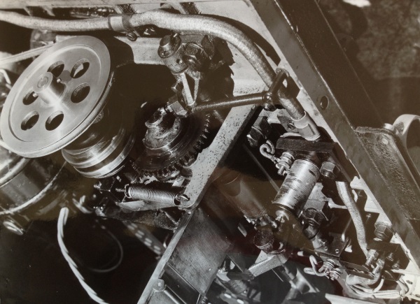
The image above shows the drive pulley which is driven by the visible belt which is driven by the motor pulley which is not in view and to the left of the photograph. The body of the drive motor is visible to the left of, behind and below the visible pulley. Neville describes this motor next.
The J8 machine ran on 120 volts DC and depending on the model it had a constantly running shunt wired universal motor, which was connected to an electric clutch which was powered at the time, when you initiated a bet and it drove the various mechanical shafts, which progressed the ticket paper, operated the print cam and at the last moment, operated the paper guillotine to sever the ticket and print rollers which ejected the ticket from the machine. Then on that print cam was what was called the home cam position and there the machine rolled into the idle position.
That type of machine was capable of selling up to 28 Win and 28 Place horse positions and one Test position was also allowed for. In later days there was a machine created which was used in North America using the J8 and it sold quinellas I think on an 8 or 10 starter field, it was a fairly rare machine. The electromechanical mechanism for initiating a bet in the J8 was a very simple arrangement with a magnetic system and this particular coil was called the trip coil and it was mounted in such a way with a latch, which latched onto the main drive cam and when the bet was accepted by the mainframe adder the current in the trip coil would rise to about 1 amp and on the peak of the rise the trip would release the print cam, which rotated through 360 degrees and during that time it performed the functions of print, guillotine and eject and then come back to the home cam position and relatch in the idle state. The adjustment of the trip coil was critical. All of the adjustments, not only the trip coil in the J8, but the horse adder, was critical as well. It was like fine tuning, you set them up and you find that your system worked well. A sort of a compromise had to be taken with a view to this, because the J8 ticket machines were never stationary. In most cases they were moved from track to track. In other words if you take the Sydney situation, the 400 odd J8s that we had stationed in Sydney, moved from Randwick to Canterbury to Rose Hill to Warwick Farm etcetera, week by week or whatever was required. They also, during the week, served at places like Fairfield Trots Richmond Dogs etcetera, to wherever they wanted, and there was a company contracted to ATL, who did the arrangements of shifting the machines from track to track. Therefore you would find a machine at one track say at Randwick and it would be anything up to a couple of kilometres from the main tote room, via the way of the cabling system worked, one day and the next day, it would be sitting in the room next door, so the voltage drop in the cables had to be taken into account in setting up the trip voltages. Sometimes it was necessary to adjust these on the bank testing on Fridays, prior to a race meeting, but fairly rarely.
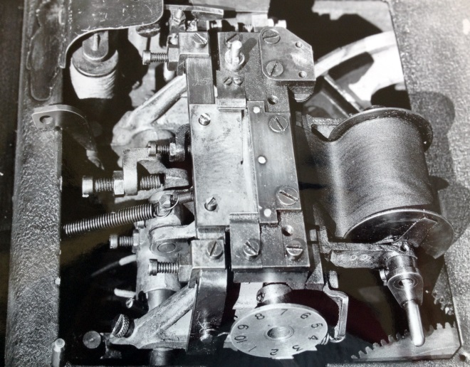
The other coil you will notice in the J8 is the race change. This is the same sort of set-up and it had a barrel, most of the barrels had 8 or 10 positions. I think the disk with 1 to 10 marked near the perimeter in the image above is part of this assembly. It was a die cast aluminium barrel which had the numbers 1 to 8 or 1 to 10 on it and there was another barrel associated with that called the code barrel. These codes were kept secret and they were only issued out a few minutes before the first race at any race track and the code barrel was lined up in a special way. The mechanic in charge of the tote house would be given a box with all of the code barrels and race barrels in it. He would then open an envelope when he got to the tote house and it would tell him the code of the day so he knew which code on the barrel to start with. He inserted that and then wound the clockwork mechanism of the race change back to race one. At the end of race one, the race engineer, the person in charge, or the totalisator manager for the day, would call up a race change and a push-button was operated in the main control room, which caused all of the ticket machines to rotate to race two and consequently show not only the race number but the new code word. In those days the ticket paper was changed for every race. This was also kept secret, as to what paper would be used and it was only notified to the tote house managers a few minutes before race one, so that the people who were involved with the paper delivered a roll of paper to each machine which would have a special background a certain colour and on the selvage edge a certain code letter or number and these 8 or 10 numbers would be kept secret until race 1. Most of the time, the ticket machine operator did her own paper change. At the end of each race she was required to jump off her stool, wind the remaining paper back from the machine and put a rubber band around the remaining roll, put it to one side and install a new roll of paper with its proper code on it in the machine. This code and number was displayed on a chalk board. She then inserted the new paper and the first thing she did before she was allowed to open her window was to take a test ticket and display the test ticket on the machine so that the tote supervisor would come down and check to make sure that she had race two up with the correct code on the correct paper. All this information of course was passed through to the pay clerks and they checked that when a ticket came in as a pay ticket, a winning ticket, that all of these things, the race number the race code the race paper and the colour all coincided so there was this backup to prevent fraudulent operation of the system.
The later model J8s had an intermittent operating 120V motor. This was to reduce the amount of 120V power we had to provide on track. In most cases 120V DC was provided by an engine generator set. Some of these were quite large for instance at Randwick it was driven by a very very large, Harland Wolf stationary diesel engine and would be something like you would see in a powerhouse, or a fair sized ship. It was manned all day on race-day. In later years they were replaced by silicon rectifier systems made by Oliver Electrics in Brookvale. I remember the owner of Oliver Electrics, a Robert Oliver, Robert was a very good friend to me over many years. He was from the old school of business always upfront and his company produced excellent products. These rectifier systems were capacities of 300 to 500 amp machines, quite large, very reliable. We did away with running the diesels on race-day although we had them manned and in the event of a power failure we would crank up the diesel and switch over to backup power. This system was universal. In other tracks such as the trotting tracks and the dog tracks, the requirement was not for so much power and the generators were coupled to Ford V8 engines or Red Diamond engines which were a flat six and they were developed in America for stationary engine work. Those stationary engines were very very old when they were retired. The ones in Caulfield had been installed back in 1938, or something and they were retired in 1965. They still ran sweetly and they were of great value; but they went to Mr. Simms for demolition I expect!
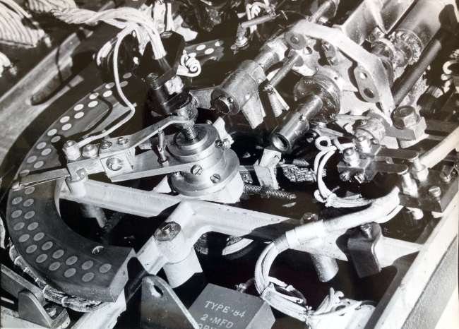
The Horse Halo Neville mentions below can be seen as the semicircle with two rows of studs on it in the image above. The wiper arm that sweeps across the arc is connected to the runner selector handle on the top of the machine. One arc of studs is used for the Win pool and the other for the Place pool and each stud represents a runner. Notice the 2 MicroFarad paper capacitor at the bottom centre of this image. When I started work in the electronics industry in 1970, this type of capacitor was very common in existing equipment. I have not seen one of these in a very long time now!
Another major part of the J8 was the Horse Halo assembly. It was always manufactured as a separate part of the machine, even the wiring loom was a separate part. It was wired up in a loom machine and then laced with cotton rayon and later on a nylon lacing to make it neat and tidy. The cabling was always in a 1/.024" tinned copper wire with what they call a Forderson covering which was PVC and then overlaid with a waxed cotton. This seemed funny for something that was often opened and closed so you had the cable form bending but I never ever found a broken wire. The 24 starter Win and Place halo was manufactured from a pressed canvas Bakelite material and all the studding was solid brass and the contacts were always pure silver with Phosphor Bronze contact springs and later it was German Nickel Silver contact springs.
All of the spring packs and switch packs in the machines were manufactured entirely by ATL all of the componentry with the exception of the motor was manufactured in Meadowbank. There was very little of the machine that was brought in, there was only things, like there might have been some power resistors, certainly the bypass the spark suppression capacitors and the like were bought but there was only very few of them. You could say that 97% of the machine was manufactured in house. The design of the J8 was done by Julius himself and as I said it progressed from the J6. All of the drawings for the original J8 were kept by Julius at his company called Julius Poole and Gibson at the time. It was only as time went by, that the total design evolved to the point where all the mechanical drawings were actually held at Meadowbank. This was brought about because of the change from hand machining of all of the components using turret lathes and the like progressing to the MC controlled work centres, lathes and mills and drills and the like, so the drawings and to some extent the componentry changed.
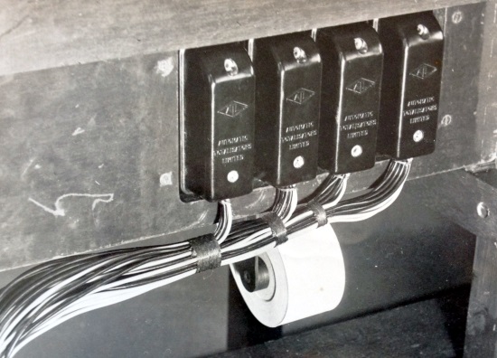
This image shows the ATL plastic moulded 16 pin connectors that Neville mentions below. They were used to connect the ticket issuing machines to the race tracks and also the adders to the mainframe. Note the moulded ATL diamond logo on these connectors as well as the words Automatic Totalisators Limited. This photo also shows the TIM's ticket paper supply roll. This is looking underneath the ticket issuing machine bench-top.
The J8 never suffered the indignity of being plasticised, like machines after that. There was a lot of plastic mouldings and extrusions and the like used in them to bring down their cost and put up their reliability. The Bakelite components in the J8, the pot moulded or compress moulded systems, again this was all in-house, the pot moulding pressure machine was a HINE I think 75 Tonner and they'd mould all of the parts for the J8, the 16 pin sockets on the back and its mating female component that connected the machines to the race-tracks.
J8s were installed in a specially designed bench in the selling houses with a couple of running rails these were necessary because when you opened the machine it was front heavy and it would topple over if it was not properly inserted in the running rails. All of the selling houses were cabled back to the main tote and the horse adder arrangement with various types of cable, mostly it was lead sheathed cable and then armour chord cable and a lot of the internal wires were paper insulated and enamelled cables later on it was VIR type cables and then finally into the PVCs. In each selling line there would be a main pothead at the end of the selling line which would have the number of banks(of TIMs) at least 5 shillings 10 shillings 1 pound etcetera data lines coming in which would be wired out to each ticket machine depending on its assigned value.
I have never heard the term Pot Head mentioned in the last sentence. I asked Neville about this and he provided the following explanation:
Each one of the J8 ticket machines had a priority select system which was called W and P or Win and Place. When the operator of the machine placed a bet by selecting the horse number by rotating the runner selector arm shown in the top view of the J7 above and pushing the knob forward or backwards to select the Win or Place pool she then pushed the control button down on the swing arm and this would operate a set of contact switches which would put up a call on the Win or Place line. This would be seen back at the control room on the distributor so each of the ticket machines in the various lines would have two control lines going all the way back to the machine room. The DC power plus and minus 120V was sent along there as well, the race change cabling of course and there was other things like the scratching annunciator, which was a lamp panel which lit up with the horses that weren't running in a race or in some cases it was the other way around where all the horses that were running were lit up and the scratchings were not illuminated. There was other things like stop betting bells and pay bells and the like and of course a magneto telephone system that connected the selling lines to the main tote room. That just about covers the J8 situation and we will move on up to the main tote.
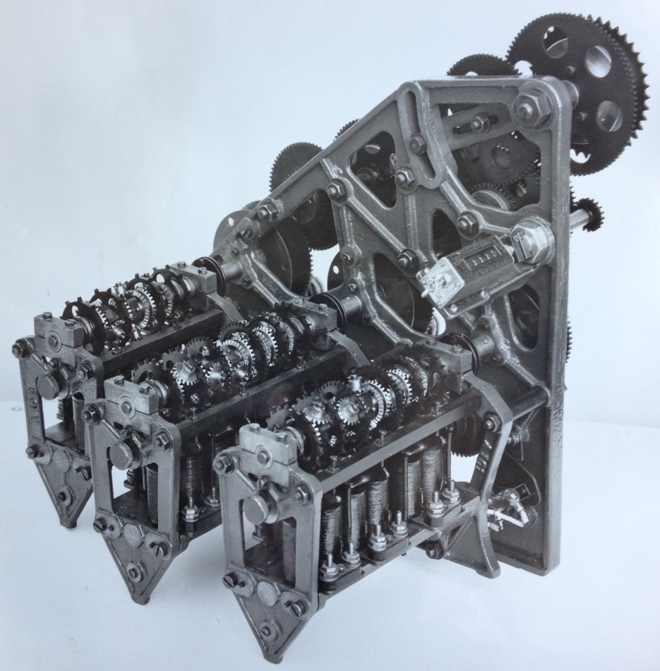
The developing machine started off from very simple two shaft adders, with two escapements on them with two values maybe a one unit and two unit or a one unit and a four unit escapement mechanism and as time goes by they got up to the point where I think where Randwick was the largest one in Australia that used ten channels which was a large number of 5 shilling channels followed up by a sort of a ratio of 10 shilling and one pound escapements.
Neville mentions the large adders. The adders in the Eagle Farm Mainframe image have an adder in the lower half of each window of the frame. As can be seen the large adders at White City have a whole table for each adder. Below is an image of one of the many large shaft adders at Longchamps
An example of the many large shaft adders at Longchamps.
The horse adders that you have got here at Mona Vale I think one is pre-war and they look to be in fair condition. The adder of course is mounted in your steel frame and engages with a drive shaft from which it picks up the energy required to operate the bet escapement wheels. There is a take-off gear which is driven into a friction clock spring which had a certain number of revolutions stored in the clock spring in other words in the event of a power failure or a drive failure, the bet in progress would always be finished in other words there is enough stored energy in the shaft to maintain the system up until the last bet issued by a machine somewhere on the track would be accepted by the adder.
On the machine there was certain alarm conditions set up, such as if the machine was going too fast and had not caught up, in other words the adder was going faster than the input shaft, there was mercury switches in the glass tubes, which tilted to indicate that the bet storage system was exhausted and this alarm would come up and it would actually signal back to the distributor system and would cause the distributor to pause until the machine was able to catch up. This was not much of a problem in Australia but in Asia, where the rate of betting and the number of machines was always at capacity it was a problem and they got over it, over there, by having a guy sit on the end of the machine with a rheostat controller and he would control the input shaft speed so that when the alarm lights and alarm bells were ringing, he would crank up the speed of the input shaft, so there was more capacity to pick up the bets.
The readout Neville mentions next can be seen in the middle right of this photo. There is a butterfly type of knob on the near side of the counter used for resetting. This type of adder is the sort that would be housed in a frame similar to the one shown in the Eagle Farm Racing Museum photograph. There is one adder in each of the windows of the frame in that photograph. The difference between the adder shown here and the ones in the frame of the machine in the Eagle Farm Racing Museum is that the above photo shows a 3 shaft adder and the Eagle Farm Racing Museum frame has 2 shaft adders.
The readout from each adder was achieved through a rotary counter. These were normally an American machine and they were chosen for their reliability and ease of resetting and they lacked mechanical problems which were common in other designs and in particular the European design of counters tended to be a bit of a problem. At the beginning of any race period the adders were always reset. That means the counters were reset to all zeros and this was carefully checked. There was always a possibility that if all of the decades of the counter hadn't been set back to zero there would be a lack of carry. In other words if the tens digit had not reset properly the unit digit would rotate and instead of carrying on to the tens would miss the carry and the machine would not count properly so there was always a second test to ensure the counters were reset.
For this section refer to the photo of the mainframe in the Eagle Farm Racing Museum photo. The normal tote system there would have been 24 Win adders and 24 Place adders and at the end of each one of these banks of adders Win and Place are the GT (Grand Total) adders. Normally the GT adder would not be any different to the horse adder except the counter may have had a larger capacity. In those days there was nothing near the bet numbers like we have today.
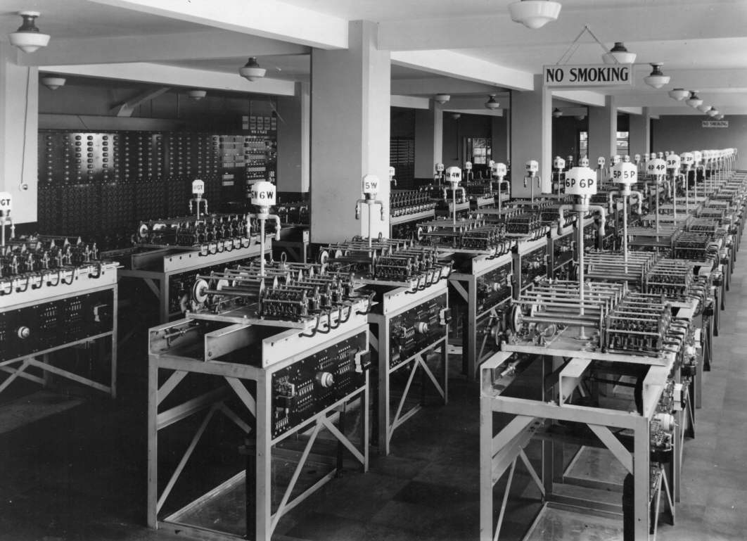
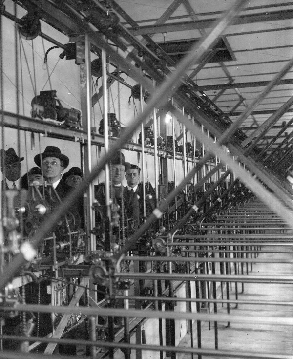
Sir George Julius inspecting the new installation at Flemington 1931
The above photograph provides a good view of the odds calculating devices Neville describes next. The vertical and horizontal transport mechanisms for the vertical and horizontal sliders are visible. There are two banks of adders in this frame. There are adders in one bank, the top of which are at shoulder height of the people in the photo. Only the first 3 are clearly visible however there are adders for the full length of this frame and they tend to fade into the distance, however the silver conical end caps on the adding shaft drive clutches can be seen in the distance. These adders in the one line represent one pool. There are normally two pools supported by this version of these systems Win and Place. The second pool is catered for by a second bank of adders that are not in the field of view of this photo and are off the right hand side. The hypotenuse arms creating the right angled triangles, by joining the horizontal and vertical sliders can bee seen at a 45 degree angle. There are two sets of odds calculators visible in this photograph. One set for the adders visible in the photograph. The other hypotenuse arms forming a cross effect come from the adders on the right hand side of this system which are out of the view of the photograph. The hypotenuse arms are very prominent. The right angle for the odds calculating triangle of the adders in view is on the left hand side. The right angle for the odds calculating triangle of the adders not in view is on the right hand side. As a result the hypotenuse arms for the adders in view decline towards the right and the arms for the adders not in view decline to the left producing the cross effect in the photo. The gradient of all the hypotenuse arms with respect to their respective right triangles are the same in the photograph. This is due to all of the odds calculators being set to an initialised state in the photograph and during a meeting when the system is operating, the gradients will all be different representing the odds for their respective runners. The angles at the top of the right triangles represents the odds. Mathematically the cotangent of this angle is the odd for its associated runner as the vertical slider represents the net pool total and the horizontal slider represents the investment on the runner that the associated adder is totalling. In other words the gradient of the hypotenuse arms represent the odds.
The odds were determined in most cases by the mathematical equation caused by the angle of the hypotenuse on a triangle and there was various ways and means of this being achieved in different systems. The one you have down there is where the horse adder allowed the bottom of the triangle to expand and the GT allowed the top to rise and the angle across them was measured and the this angle was read out in various ways to indicator equipment. In the equipment you have there it was into a tube type indicator which drew brass blinds up and down in a chute and the internal of the chute was sign written with the odds pertaining to that runner. The GT adder was coupled to what was called the GT gearbox. This was a gearbox which had a series of interchangeable ratios and it determined the commissions which were taken out of the race pool to pay the government taxes, the racecourse commission and the commission for the tote operator etcetera and they ranged from all sorts of numbers from very low figures such as seven percent up to as much thirty percent in certain cases like Greyhound racing that was a thirty percent take-out and the Win and the Place was seventeen or eighteen percent or something like that. I did not see one of them there but I hope there is something like that in the stuff that is stored.
The housing Neville mentions below is seen in the first image in this section of the Eagle Farm Racing Museum mainframe. He also mentions the adder windows being glassed in. The frame in this photo has glass panels and they are all retracted in the photo except one which is third from the right and has a descriptive A4 page attached to it.
The drives to the main take-off shafts was usually by Universal type motors 120V DC and I think they were about 5 horse power. From what I can remember of them, they were Australian made by Davies or Comptons at Airzone there was quite a few companies around that era, where you could buy that type of electric motor, they were quite common. With that type of motor you had good control over the speed and they provided sufficient power to run the shafts.
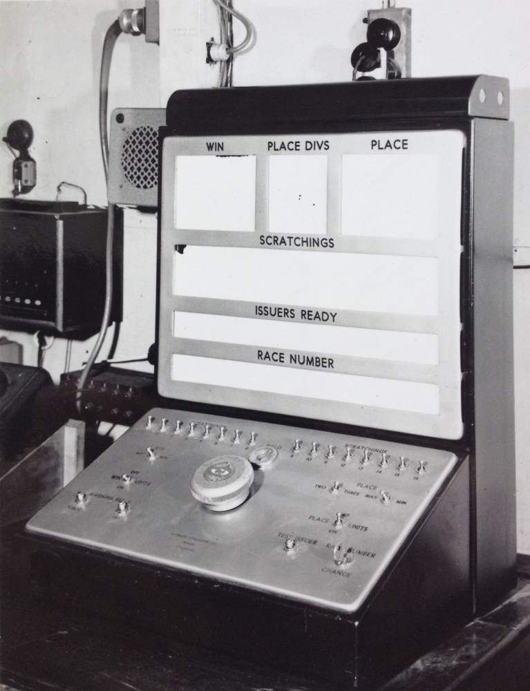
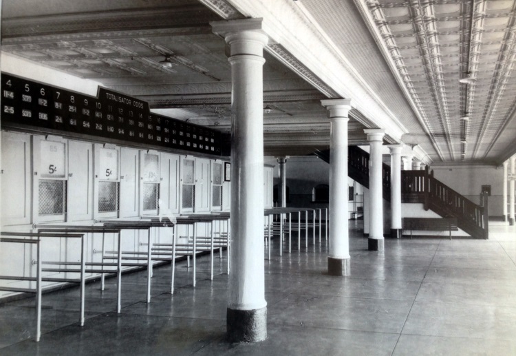
The main control Neville mentions next can be seen in the two racks under the heading Official Control near the top of this page.
It was the device where you would set up the race field in other words the number of starters the scratched runners and there was a large knob on that which was actually the petrol cap of a Ford car and that was the race selector knob. It was quite a magnificent looking piece of work. It was actually made for ATL by a friend of Julius called Gladstone and he ran his own company Gladstone Electric and they were into industrial control and nurses control equipment for the hospitals, the bits and pieces where you pushed the button and it called the nurse etcetera. They did all that sort of thing and for some reason or other they also made these tote control consoles.
The image above is taken in the Eagle Farm Racing Museum so there is a lot of Museum display around the racks, however the scanners are visible. They are the circular devices central in the photograph, at the top of the racks. In modern terminology these are time division multiplexers which existed long before the digital signalling methods that made this concept commonplace.
There are complications in it of course which come about with the alarm systems which detected faults. There is no need to worry too much about them at this point. That process of a series circuit which is simply as I said before, the positive asserted from the J8 Ticket Machine to the stud on the distributor, the stud on the distributor was detected by the distributor arm, the distributor arm is disabled by the overlap relay, the overlap relay asserted a positive again back to the ticket machine via the horse adder, the GT adder, the trip coil in the machine, the machine cycled the bet's been recorded, and in the cycle, the bet information was printed on a piece of paper and ejected from the machine. This process carried on at the rate of about 90 bets per minute per machine on the track. As you think about it, it's a fairly simple process. Because of the intricacies of the electromechanical system and the vagaries of it all it required a lot of fine tuning to get the system to work accurately in the first place and once that was done these machines were highly reliable and any sort of malfunction was investigated thoroughly.
The mystique of the machines was something I experienced particularly in Melbourne, not so much in Sydney. The men who operated the four major tracks there had been with these machines since 1936 and on their decommissioning day I saw emotions that were quite unbelievable. They were seeing the last day of operation of this sort of gear. The strictness with which the engineers ran these systems was somewhat akin to a military operation, they really had a lot of power. They had a lot of routines set down and to be an apprentice in those days was a lot of sweeping the floors and making the tea for a long long time before you got your hands on any piece of equipment and I believe in the early days of Melbourne that if an apprentice was seen with his hands out of his pockets in the machine room he would get a swift slap around the ears. The same thing applied in New Zealand, I read some stories from there and I actually knew a couple of the engineers from over there too and they applied the same very very strict mode of operation with their set-ups. They were extremely proud of these machines and some of them spent you know all of their, what we could call idle time, on routine maintenance and polishing of brass and things like that, that made these machines absolute show rooms. Wherever you went in Asia for instance, you looked at the machine that was covered in mould, they worked perfectly, but there was no mystique about them there at all, but here in Australia and New Zealand the men who worked on them, loved them.
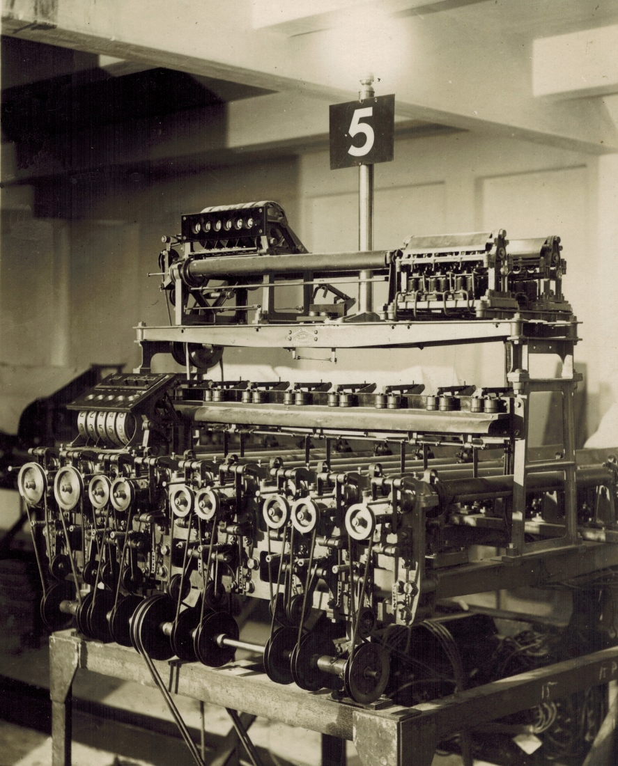
This image is an example of the enormous machine Neville refers to next which shook the building.
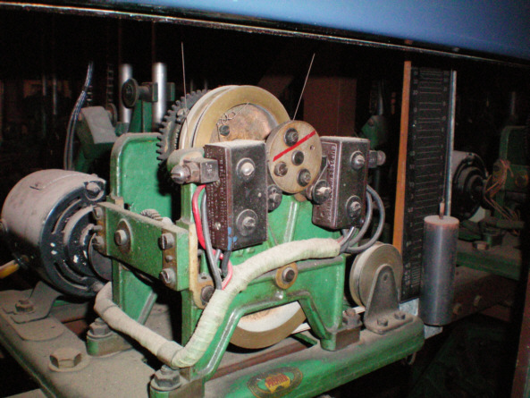
The hypotenuse system Neville just mentioned has already been covered above. Below is an image of a Selsyn motor indicator drive he mentions next.
A Selsyn Motor and Barometer Indicator Drive Unit in the Eagle Farm Racing Museum
There was the Selsyn systems which used the Selsyn motor transmitters which I think was an invention that was used back in the early part of the century for guiding guns from a remote location. You could move a transmitter motor from a certain point and a follow up motor, the slave motor, would follow you segment by segment, a bit like a modern stepping motor. Then there was the Wheatstone principle as well where the output from the hypotenuse was driven into a potentiometer device and that was wired up in a Wheatstone principle to a receiver device. Many of these were blind indicators something like you see on a government bus and they again were a shaft driven device with electric clutches and the null point of the Wheatstone principle, was used to drive positively or negatively on a polarising relay which would drive the blind up and down. There was a neutralising switch which would hold the blind in the appropriate display position, providing the balance wasn't too bad the blind would remain there. There were lots of problems with that, with changes in temperature between the control room and the outlying indicator buildings. You would often get variations of a point or two, between the display on the main tote and the display on the remote locations. In later days we had all sorts of devices that converted the data from the adder. We had epicyclic devices that could output the data unit by unit and we could decode that and display it in lamp panels with various configurations of dot matrix, six by four patterns, and five by seven patterns and nine by six lamp patterns and in lamp box sizes from 75 mm up to 600 mm and with lamp wattages from one watt to twenty five watts.
Some of those installations we did back in the 1960s are still in operation, notably in Melbourne, South Australia and all through Asia. They are well into their thirty years of service and still going. The same applies to a lot of the indication systems in Happy Valley in Hong Kong. Their big problem up there, is that the cyclonic conditions can certainly do damage to them and I imagine that by this time they'd probably be looking for replacements.
This photo relates to Neville's next section where he mentions the Projector Indicator at the Lady Members at Randwick. The area this photo is taken in was a real revelation for me when I visited Randwick around 2009. Walking underneath the staircase and then to the wall and turning right there is a dungeon like door. When I first saw it in recent times it seemed to hold an uncanny attraction I could not explain. When I worked for AWA the first time around in the early 1970s, I worked in the field engineering department and one of our tasks was to operate and maintain the closed circuit television system at Randwick. Shortly after this recent at the time, look at Randwick, my friend Mick gave me a nostalgic tour of the track. I was surprised when this tour took us to this dungeon door I mentioned and was even more surprised to find Mick unlocking the security door. Once the doors were open and an equipment room was revealed, the revelation hit me! This was the room that housed the TV head end in the days that I visited the track on racedays with AWA. It was also the room we used for temporary holding of faulty TVs pending returning them to our factory for repairs. I had totally forgotten where this room was. It was the first place on the track we visited as the equipment here had to be turned on before any of the TV system worked. I used to go with a senior technician as I was a trainee at the time. When I visited with Mick, this room had a lot of communications equipment and some television equipment. I remember seeing some Digital Images International VDGs (Video Display Generators) or UDCs (Universal Display Controllers), I cannot recall which.
Other indicating systems which were popular with that era of machine was a projection system. Again the Wheatstone principle was used and there was a rotary glass disk which was the positive of the odds display and there was a set of condenser magnifying lenses and a very very powerful projector lamp and it projected the display onto a frosted glass panel. These were interior designs and they were always inside somewhere, such as the Lady Members at Randwick or the Lady Members at Caulfield and it showed the bookmakers odds for the tote. These were also very good except again, the problem with temperature differences was always there. We dismantled the one at the Lady Members at Randwick and I managed to get hold of one of the power transformers and I converted it to a very successful electric welder which I had for many years.
The J8 ticket machine was in itself an evolution. The first of the ticket issuing machines was from the Julius Engineering shop at Cammeray and by 1948 the J8 was a successful machine. It took many years for the evolution of the machines to finally arrive at the state that they are in now where it's been taken over by the PC. The last machine that I worked on which was the J52, believe it or not, was a PC based terminal with a printer and a bar code reader and a sophisticated dedicated keyboard. All trace of electromechanical had disappeared. The J serial numbers between 8 and 52, there was very many of them that were project built, given the title and they never went into production. This was because the project for which they were built was lost to some other competitor, or for technical reasons or financial reasons the customer selected an existing machine or something like that. There was quite a lot of very successful ones in amongst them the J10 which was the first of the true doubles and quinella machines. The J11 was a highly successful machine that was dedicated to the North American market and it kept Automatic Totalisators in business for many years on its own. The production levels for that were enormous. The J18 was another highly successful machine designed for the Australian scene namely for Victoria. The next one was J22 which was designed exclusively for the Royal Hong Kong Jockey Club in Hong Kong another very very good machine it was a microprocessor based machine and was the first of the machines to have barcode reading. The J31 was a machine designed for the telephone betting systems and it went into Hong Kong and Malaysia and places like that where telephone betting was becoming the leading off-course operation. The J42 was another microprocessor based machine and all of these were heading towards being PC based.
I hope the foregoing stories and anecdotes and information has been of some interest to you and I wish you well with the project. Any further help I can give you please don't hesitate to enquire.
I have included an extract from an article Neville has written titled "Randwick Results Indicator By Neville Mitchell" the rest of which, is presented in the chapter of this website titled "Automatic Totalisators Limited - Later ATL". I have presented this segment here as it relates to Randwick which is mentioned multiple times in this chapter and it also relates to the Ticket Issuing Machines. The upgrade Neville describes took place during the end of the electromechanical era when electronic systems were becoming popular
The off-course totalisator race day takings were far larger than on-course takings. There was no method available to automatically add the off-course figures to the on-course. Off-course figures were telephoned to the on-course control room and then individually added to each race runner's totalisator figure using a custom designed calculator, the odds for the runner was determined and manually entered onto a mobile ODDS CONSOLE, then were displayed on the Lady Members win & place indicator which was scanned by two CCTV cameras to be screened on multiple TV screens placed around the public areas.
The Julius electro-mechanical Totalisator machine was at this stage fully equipped and all available ticket machine access positions were occupied. The upgrade took the form of raising the ticket value. The fifty cent ticket machines were raised to one dollar, one dollar up to two dollars, five to ten & ten to twenty. To achieve this without having to rewire the ticket machine a device called a MULTI IMPULSE SET was used. This gave two adder impulses for each ticket issued.
The other method of adding higher value ticket machines was via a device called a PRIORITY RELAY UNIT. This device allowed two ticket machines to share their access lines. This was ok when betting rates were slow however there was a noticeable delay during heavy betting periods.
The ageing J8 ticket machines were sent in batches to the Meadowbank factory for a general overhaul and refurbishing. Otherwise they were 1950's machines in excellent working order.
The bottom of a J7 Ticket Issuing Machine Showing the Horse Halo
 Go back to the index
Go to the bottom of the page
Go back to the index
Go to the bottom of the page
Some Plastic Moulded ATL connectors
At all Sydney racetracks the cables to the tote terminals were armour plated with steel wires laced around the paper insulated Varnished conductors, the entire cable was filled with an "oily" substance.
In the main totalisator house the cables were terminated in cast iron housings with a marble plate known as POT HEADS with 52 brass bolts with nuts and washers the cable was stripped of its insulation and passed through a sealing gland then each conductor was cleaned of its varnish insulation and soldered to the back of the brass bolts. There were 24 Win and 24 Place connections, plus race change. I think the 50th conductor was the start/stop betting bell? Conductors 51 & 52 were + and - 120 volts. Each Tote selling line had the same POT HEADS, one for each bet value and a terminal select POT HEAD for the W/P bids.
The wiring pattern was standard, for all tracks.
There was provision in each POT HEAD to refresh the Oily substance via a screwed plug in the top of the POT HEAD. I never saw this being done.
Over time some of the brass bolts would loosen and attempting to re-tighten them caused the soldered conductor to fracture and break off, it was a real dirty difficult task to do a re connect. Often we just marked the conductor as open circuit and switched the circuit to a spare pothead, making a note of where the conductor was. The cockroaches would eat the note of course!!
I'm not aware what type of POT HEADS were used in Brisbane or Adelaide, when PVC cables were installed the standard ATL open frame terminating array was used.
The Main Tote
The Main Tote mainframe in the Eagle Farm Racing Museum
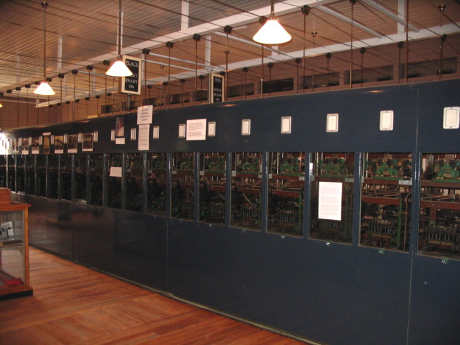
The main frame of the tote was usually enclosed in a housing and most of them were simply made of angle iron frames covered in Masonite and this was painted, normally a green colour and in a few cases the adders were glassed in and you had to open a window to get at an adder. In Asia this was a damn nuisance because the adders used to run at such a pace it would actually cause the oil on the shafts to vaporise and it would smear up the glass and you couldn't read the counters. It didn't matter much up there because we just employed a kid with a rag with some turpentine and go around regularly just to clean the glass, but in Australia it was a bit of a nuisance.
The main control of the tote system was usually in a console, a six foot rack, for want of a better word and it contained all of the DC distribution systems the alarm systems and the determination as to how that was displayed with bells and red lights etcetera and race number change control system and often there was a thing called a Tote Control Console, I didnt notice one of those but I hope it is in there somewhere.
A Julius Tote Control Console
 An image of the scanner racks in the Eagle Farm Racing Museum
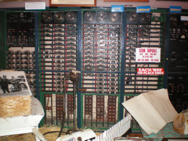
The other piece of equipment that is involved in the control room was the distributor. This was a rotary device and I notice the one you have got there is a three header with commonly twenty nine studs per group or may even have fewer than that sixteen or nineteen or something like that. Each one of the studs, and there is two rows per distributor, was the Win and the Place stud related to any particular ticket machine on the track. So as I explained from the J8, there is a Win and a Place which are the priority lines or call lines or bid line and when a bid came up it put a positive onto the stud on the distributor and when the distributor arm reached that stud, it would operate a relay which was positioned in the same rack and this relay was called the overlap relay. It would detect the positive and it would then switch the distributor arm off and apply a positive through the whole system and this positive would flow via the contacts in the overlap relay to the horse adder escapement coil, in the particular value you wanted, say we are looking at horse number five and we have put a five shilling bet on, then in series with that it goes through the grand total adder operating an escapement in the grand total adder it flows through the cabling to the J8 ticket machine, where the trip coil, when it reaches the peak current of one amp, would have tripped and at this time the overlap relay drops out and re-enables the distributor arm so that it is enabled again and it can pick up the next stud it comes to with a bid on it. This is the basic principle of the whole machine.
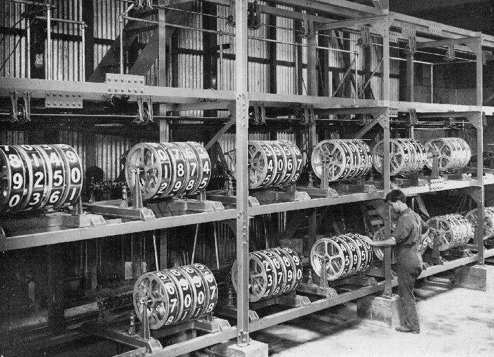
In the display of odds and the like there was certainly an evolution. In the very very early days the actual readout of the adder was onto a giant drum probably 600 mm in diameter, and the digits nought to nine were displayed on them and there would be whatever number was required to display the amount of tickets that were sold on a particular horse. These were enormous machines and beautifully made and I reinstalled one back up in Thailand, back in 1969 I think and I was quite amazed at the ingenuity of it and how large it was and some of the techniques used. They had switching circuits for the decade counting from one digit to the next, they were mercury pots with probably 25 mm diameter pot 30 mm deep that was filled with mercury, one side by side and then a fork like affair which was the switch, would dip into it and that would create the circuit to the next decade. You could imagine how absolutely accurate that was, there was no chance of a dirty contact or a miss-up in a non-transfer, however when you got these big machines working rather quickly the building sort of shook a bit. There was other systems that was related to that era of electromechanical tote with the odds calculation using the hypotenuse principle.
A Projector Indicator in the Lady Members Randwick
A look at the Ticket Issuing Machines
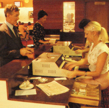
J22s in operation Guineas Room Eagle Farm 1979
Randwick Totalisator 1968 Upgrade
![]()
Acknowledgements
Comments and suggestions welcome to
totehis@hotmail.com 
| Previous page | Go to the index | Top of the page | Next page |