This technology history page contains a photograph, which is one of several belonging to the photo gallery pages, which are part of several pages relating to the invention of the world's first automatic totalizator in 1913 and Automatic Totalisators Limited, the Australian company founded in 1917 to develop, manufacture and export these systems.
Electromechanical Computing on a large scale
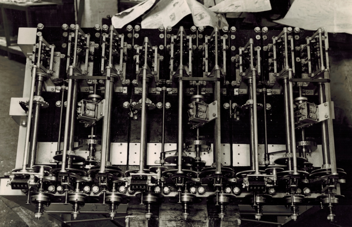
Brough Park Newcastle 3-3 shaft GT Adder top view
This photograph is of an electromechanical Grand Total Adder for Brough Park racetrack Newcastle Upon Tyne. The installation of this system was in 1936. The photograph was taken in the ATL factory at Chalmers Street Sydney. The writing on the back of the photograph reads: 3-3 shaft Grand Totals on one frame. (W.P. and F'cast) Note "chasers" for transferring the odd units to drum indicators at close of betting. Also, cam operated tens transfer contactor. Picture taken in factory. Labels &c not put on machines at the time. W.P.and F'cast in this text stands for Win Place and Forecast pools. The tens transfer in the tens transfer contactor refers to transactions that are being recorded as tens of the base unit of investment. If the base unit is a shilling then this associated equipment is recording 10 shilling units, speeding up recording. If you are not familiar with &c in the note, it is an abbreviation of etc. which is an abbreviation of etcetera.
Storage Screws a mechanical memory plus chasers and tens transfer
On the back of the previous photograph in the Photo Gallery which is a front view of this same adder, there is a very interesting comment as it refers to the storage screws in this adder. The Storage Screws are very interesting devices for technologists interested in computer history. Storage is a very important concept associated with digital computers. The storage screw is a form of mechanical memory which is analogous to buffer memory in digital computers. Rotation of the adding shafts, which represent bets, are stored in the respective storage screws and read at a slower rate by heavier equipment, like the drum indicators mentioned in the writing on the back of the photo, which cannot respond as quickly due to inertia. Additional information is available following this photograph.
Click on the image to go back to the Photo Gallery
There is no photographer's stamp on this photograph
This top view of this adder makes some of the storage screws mentioned, clearly visible. There are nine constituent shaft adders in this 3-3 shaft GT Adder. As the writing on the back of this GT Adder photograph indicates, three of these constituent shaft adders and their associated machinery are for the Win pool, another group of three are for the Place pool and the final three for the Forecast pool. These nine constituent shaft adders occupy the rear one third of the adder and can be seen in the upper half of the photo. The heads of seventeen bolts can be seen along the rear edge of the adder near to top edge of the photo and an eighteenth bolt head is covered by a piece of paper in the top right corner of the photo. Each pair of these bolts attaches the rear end of their associated constituent shaft adder mounting plate to the frame of the whole 3-3 GT Adder. Part of the constituent shaft adder frames which are visible are rectangular in shape and are longer in the front to back axis of the whole GT Adder than the side to side axis. This is clearest in the centre constituent shaft adder as this is the adder closest to a perpendicular down view of it. Looking at the constituent shaft adders it can be seen that the first one on the left of the whole adder is a short one followed by two longer ones and this is repeated two times on the right to make the three groups of three constituent adders. Rising above the short sides of each constituent adder's rectangular frame are triangular shaped brackets with rounded tops supporting a rod running between the apex of the pairs of brackets. These rods are the highest point in the individual shaft adder assemblies. This is all part of the mounting assembly. Below these rods are the solenoids, escapement wheels and mechanisms and the epicyclic gears that drive the output shafts of each of these constituent shaft adders. At the bottom end of each of the rods that constitute the high point of the constituent adders in the photo, the end nearest the front of the complete adder, there are another nine thicker rods that are also part of the framework of the whole adder. These sit higher than the rods above the constituent adders and run from their position on the near side of the constituent adders, to the respective mounting assemblies of the cogs at the front of the adder seen at the bottom of the photo. Below each of these long rods are circular rotating shafts. These are the storage screws. They interface the constituent adder output shafts at the rear of the complete adder to their respective nine large cogs in a row amongst the cogs at the front of the adder. Every third one of these large cogs has a slightly smaller cog mounted behind it. Actually every second large cog also has a same slightly smaller cog behind it, only mounted further back. These have to do with the summation of rotation from the units shafts which I will elaborate on later. As the nine long mounting rods sit directly above their respective Storage Screws, looking directly down on them they hide the Storage Screws. This is evident for the three central Storage Screws, however the three Storage Screws on the right and the three on the left of these central three, with their lateral perspective, can be clearly seen. About a quarter of the way down these storage screws on their way to the front cogs, the first storage screw on the left as well as the fourth and seventh, have a circular cam wheel with undulating perimeters on each of them, that make them look like Tea Biscuits. These cam wheels are the cams, referred to in the text on the back of this photo, as extracted from the quote above, cam operated tens transfer contactor. The cam followers, that follow the undulations on the perimeter of the cam wheel and the contactor mentioned, can be seen on the left hand side of these cam wheels. These contactors transfer the transactions recorded as units of rotation on their shafts to the display equipment via pulses. When contemplating the computer era analogies to this equipment this is a form of signalling. One of the simplest forms of electronic signalling is the Return To Zero (RTZ) method and although there is some similarity there are major differences. The pulses transferring investment data is different but still recognisable as a method of data transmission so long ago.
The purpose of the storage screws is to buffer the rotation of the rapidly accelerating adding shafts from machinery that is slower to respond due to inertia. For more detail on the storage screw have a look at the first photograph in the Brough Park section of the Photo Gallery which can be reached by clicking on this photograph and selecting the thumbnail in the directory for the image above the thumbnail for this photograph. As identified in the previous paragraph the tens transfer contactors exist on the first fourth and seventh storage screw from the left. Additionally, Chasers are mentioned in this note, "chasers" for transferring the odd units to drum indicators at close of betting. I have not heard this term before however the note refers to the odd units connecting The Chasers with Odd Units. From the note on the previous photo in the Photo Gallery, which is a front view of this same adder, it states that this adder has two units shafts. From this we can deduce that this GT adder is arranged in three groups of three shafts, each group consisting of a tens shaft on the left followed by two units shafts on the right. Looking at the photograph there is an assembly with what appears to be a two coil solenoid installed, located between each pair of unit shafts in about half way between the front and the back of the GT adder. There are three of these assemblies and they are sensing something on the three shafts which have numbered drums on them. I can see in a high resolution copy of the image above that these shafts in between each pair of units shafts is driven by an epicyclic gear summing the rotation of the two units shafts either side of them and consequently I will call this shaft with the chasers a Units Total Shaft. This makes it clear that these three assemblies with the two coil solenoid in them are the "chasers". It is interesting to note that the chasers and the tens transfer contactors are transferring investment information to indicator equipment for public display. Going back to the epicyclic gear summing the two units shafts this gear is visible in the image above although not in detail. Have a look at the Units Total Shaft between second and third storage screws in the image above, that has a chaser and a numbered drum on it. Now look below the numbered drum in the image, which is moving towards the front of the adder, we come to a small cog. This meshes with a much larger cog on the first units storage screw in the first group of three. The small cog is attached to one side of the epicyclic gear effectively inputting the units stored on the left hand storage screw. Now moving further down the photo from this small cog, towards the front of the adder we see a shiny short and wide rectangle. This has an unseen spindle passing horizontally through it on which the bevel gears of the epicyclic gear are mounted. These mesh with the teeth on the flat surface on the back of the small cog mentioned. This can be made out in the image above if you zoom in on it. Obviously it is clearer on a higher resolution copy of this image. Now on the near side of the shiny oblong or in other words further down the photo another large cog can be seen mounted on the storage screw to the right, which is the second of the Units storage screws in this group of three. This large cog sits above a second large cog on the same shaft, which is the drive cog for this second Units storage screw. This first large cog drives another smaller cog, which is mostly hidden but visible, sitting on the total units shaft. This provides the second input to the epicyclic gear mounted on the total units shaft.
The way this adder is read after the cessation of betting to find out the grand total for the Win Place and Forecast pools involves two counters per pool. Assuming the first three shafts from the left of the GT Adder are for the Win pool and the next two groups of three correspond to the Place and Forecast pools, the four digit black counter mounted on the front left corner of the GT Adder bottom right in the photograph, provides the first four digits of the Win pool grand total and the least significant digit of the count is read from the drum counter wheel on the units total shaft between the second and third storage screws. Looking at this drum counter wheel a pointer can be seen pointing between the digits seven and eight on the drum. When this adder which is sitting in the factory where it has been assembled is installed at Brough Park and has been properly aligned, this pointer will point at the digit that is required to complete the GT number. The Place Pool GT is read in the same manner using the second black counter to the right of the first and sitting above the front end of the fourth storage screw and the drum counter wheel on the units grand total shaft between the fifth and sixth storage screws from the left. Finally the Forecast pool grand total is read using the third black counter to the right of the last and the associated drum counter wheel between the eighth and ninth storage screws.
Having referred to the drum unit counter wheels that provide the least significant digit of their related pool totals, you can see on each of these counters two short posts attached to the near side of the drums projecting towards the front of the adder and separated by 180 degrees from each other. Slightly to the left of the tip of the top post on the drum counter wheel between the second and third storage screws and below the number six on the drum counter you can see the tip of a lever. This lever descends at about 45 degrees to the left passing underneath the second storage screw to its fulcrum on a rod mounted on the shiny metal base plate to the left of the second storage screw. It is clear that the posts operate this lever twice every revolution of the units total shaft. Additionally the underside of the top part of the lever mentioned has an interesting profile that the posts will contact as the counter wheel they are attached to rotates until they disengage from the lever producing the required motion of the lever and the rod the lever is attached to. The rod attached to the fulcrum of this lever, runs up the photo parallel to the storage screws to a mounting near the bottom right corner of the first tens shaft adder. I think this lever and rod are the means for transferring the tens of units for the units total shaft to the tens shaft. This lever, rod and posts is repeated for the Place and Forecast pools in this GT adder.
Regarding the equipment for public display, referred to in the note on the back of this photograph as drum indicators, as the counter wheels look like drums, there is an image of one of these Counter Wheel displays in the last image in the Brough Park section of the Photo Gallery. One Chaser mentioned above and one Tens Transfer Contactor will be attached to their respective solenoid on this sort of Counter Wheel display. As this adder handles the Win Place and Forecast pools there will be a counter wheel display for each one. I suspect there are not enough digits in the example for a GT display, so it is probably a runner display but it is still good as an example as I imagine it is straight forward to add more digits.
I have wondered why there are two methods of transferring grand totals to the Drum/Counter Wheel displays, the Cam wheel and Contactor for the tens and the Chasers for the units. Also, cam operated tens transfer contactor. I imagine that it is to do with volume. There is only one tens shaft and that will be considerably less active than a units shaft, and we know there are two units shafts per pool in this GT adder increasing the volume of bets registered further and then from the previous image to this one in the photo gallery we learned that the first units shaft, which is the middle shaft in each group of three has been sped up increasing activity of unit registration even further.
I have also contemplated why the note in this extract "chasers" for transferring the odd units to drum indicators at close of betting, states the units are only transmitted to the Grand Total indicator at close of betting. I think this also concerns my previous paragraph. I think that during the betting period only the tens of units are transmitted to the grand total public display counter via the tens transfer contactor. I have heard that with some Julius Totes the units display counter used to revolve so quickly it was a blur. Without the units display counter operating the maximum the grand total can be out is nine units. If the public display counter was missing nine units then the next unit bet sold would cause the units to be transferred to the tens shaft in the adder and this would then be shown on the public grand total display. next unit to be sold would increment the units grand total
I have noticed something in this top down view of the adder that relates to stopping the drive to the storage screw once the screw has reached its rest position. There are nine shafts extending out of the front of the adder which are the front extremity of the adder. It is clear from this plan view, that each of these shafts have springs on them and have adjustable spring retainers at the end of the shafts to keep the springs centered on the shafts and prevent them from falling off. These retainers have screws used to clamp them to their respective shafts at their optimal positions and are used to adjust the tension applied by the springs to their respective clutch plates. These springs are clutch springs. On the inner side of these shafts there are shiny silver looking circular dust covers that are attached to the cogs. Inside each of the dust covers are the associated clutches. These clutches slip when the respective storage screw is empty or in other words have updated the inertia limited equipment which are the large counter wheels in public displays of pool grand totals. Above each dust cover and to the left there are another nine smaller shafts or rods which do not extend as far out as the first shafts. These are what I have called in the previous image file in the Photo Gallery Position Sensing Rods. These provide position information regarding the position of the internal headless screw part of the Storage Screw as it moves up and down the tubular body of the Storage Screw in the vicinity of its resting position. These Position Sensing Rods pass through the centre of levers projecting down behind each of the cogs with the clutches attached. The levers have their fulcrum at the upper end of them each suspended by its associated bracket with two arms that is attached to the frame. When a Position Sensing Rod reaches its maximum extended position it will have pushed the Stop Lever into its activated position and indicates the storage screw inside the cylindrical body of the complete Storage Screw has reached its rest position when the stoppers engage. In this condition the drive to the storage screw body has to be disconnected and the storage screw is locked until more bet traffic arrives from the adding shafts. At the bottom of each of the levers through which the Position Sensing Rods pass there is a semi circular projection that is a stopper. There is a corresponding semi circular projection on the back of each of the cogs which have the clutches attached. When a Position Sensing Rod is fully extended the attached lever is also fully extended the flat part of the stopper on the lever engages with the corresponding stopper on the cog wheel which stops the cog wheel when its stopper reaches the lever stopper. As the cog can no longer rotate the clutch inside the housing starts to slip. To see these stoppers, have a look in the image at the second shaft from the left, with the clutch springs on them. I have chosen this particular storage screw to look at as it is the only one were both stoppers are clearly visible. It will probably be helpful to zoom in on this part of the image although it is clear to me without zooming. Of course it is even clearer with a higher resolution copy of this image. Behind the cog with the clutch attached to it and to the left of its supporting spindle you can see the Stop Lever descending below the spindle. The bottom of this spindle is visible and the flat section of the semicircular stopper can be seen projecting towards the back of the clutch cog. Additionally, on the back of this clutch cog the rounded side of the semicircular stopper can be seen projecting towards the Stop Lever stopper. It looks somewhat displaced from the Stop Lever stopper, as the cog in this image has stopped in a position where its stopper has not yet reached the Stop Lever's stopper and the cog's stopper is in a position above that of the stop Lever's stopper. As it is the flat sides of the stoppers that engage it is possible to deduce that the cogs with the clutches rotate in an anticlockwise direction otherwise the rounded sides would contact each other. I estimate that the cog only has about 10 degrees of rotation until the stoppers align, however the stop lever is not in its engaged position so I think there is sufficient gap between the stoppers when they align not to stop the cog were it rotating. The associated Position Sensing Rod passing through this Stop Lever has to extend further for the stoppers to engage.
I have also noticed something else about this adder that I have not noticed in any adder photos before. Looking down at any of the nine Position Sensing Rods projecting down in the photograph from the front of the adder from the centre of each of the nine storage screws, there is something that caught my attention at the tips of these rods. Every rod seems to have a knurled thumb nuts screwed onto the end of them. Each of the knurled thumb nuts have a larger diameter than the rest of the sensing rod. Immediately on the inside of each of these thumb nuts there are cone like sections that gradually reduce the diameter of the sensing rods to a diameter that is constant for the rest of the visible length of each rod. I find this intriguing as one thing is for sure and that is, that it will have a purpose. As we know, as the fast to respond shaft adders continue to register transactions the internal screw is driven further into the tubular body and the storage screw and the position sensing rods continue to follow it resulting in the protruding part of them appearing shorter and shorter and the tip getting closer to a horizontal small cylindrical component across and slightly above the top of the sensing rod and perpendicular to it. For want of a better term I will call this cylindrical component the Sensing Rod Limit Contactor. As the conical section of the position sensing rod arrives at the Sensing Rod Limit Contactor it will eventually make contact with the rising profile of the cone. Presumably the Sensing Rod Limit Contactor will be pushed up the ramp of the conical section of the sensing rod and come to rest in the small indentation on the sensing rod between the near end of the conical section and the knurled thumb nut on the end of the position sensing rod. Presumably the internal screw will be capable of travelling deeper into the storage screw leaving the sensing rod in this holding position until the internal screw returns to this position, after the inertia limited equipment starts catching up with the adding shafts, and starts pushing the sensing rod back out again on its was to its resting position. Now have a look at the centre sensing rod in this adder. I have selected this one as it is central and gives a straight on view of the supporting mechanism for the Sensing Rod Limit Contactor. It can be seen that the Sensing Rod Limit Contactor is connected to a strip of metal that projects forward from underneath the associated Stop Lever fulcrum which which is supported by its mounting bracket. This Sensing Rod Limit Contactor is is parallel with the Stop Lever fulcrum pivot rod spanning the two mounting arms. The stop lever is not visible in this view as it descends near vertical from the fulcrum. The Sensing Rod Limit Contactor supporting metal strip bends underneath the fulcrum of the stop lever and can be seen rising near vertical on the inner side of the stop lever fulcrum and the upper end of the strip is secured on a screw by two nuts. The screw projects downwards in the photo, towards the front of the adder and is parallel to the sensing rods. The Sensing Rod Limit Contactor supporting metal strips are easier to see in the previous image of the photo gallery. The screw and two nuts are easier to see if you zoom in somewhat on them. The screw securing the Sensing Rod Limit Contactor's metal mounting strip is secured to what looks like a block of wood or Bakelite, that is mounted on the metal mounting plate for the cogs and storage screws at the front of the adder. This is to isolate the Sensing Rod Limit Contactor's metal mounting strip from the frame of the adder as it is part of an electrical circuit. It is obvious that the assembly of this adder is not yet complete. The second nut on each of the screws holding the Contactor's supporting metal strips to their respective blocks of wood/Bakelite is used to secure respective lugs of insulated electrical cable segments that electrically connect each of the metal strips to that of its neighbour, so that all the Contactor supporting metal strips are connected together. These cable segments are yet to be installed in this adder. Perhaps this is done on site and this adder is definitely still in the factory in the image above. To see an adder with this cable in place have a look at the image of a White City Stadium Forecast Pool Grand Total Adder which is shown already installed at white city. To see this image, click on the image above and scroll up above the Brough Park Newcastle Upon Tyne 1936 title in the Photo Gallery Index and click on the second last image in the section above with the descriptive text beginning with the sentence Another view of the adding equipment, part of the central processing system at White City Stadium London 1933. I have included a reduced size version of that image below for quick reference.
White City London Forecast GT Adder
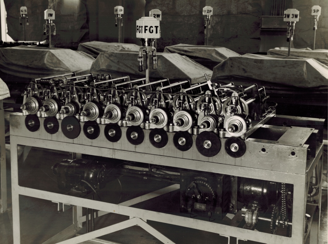
The cable can be clearly seen running across the adder near the top joining all these screws with the two nuts. You can also see another piece of equipment not seen in the main image at the top of this page. The vertical post in the middle of the White City adder with the lamp on top identifying the adder. This adder has the letters FGT on it identifying it as a Forecast pool Grand Total adder. In this adder image you can see the left hand end of this cable travels down and to the left from the connection to the first of these screws with two nuts, on the left of the adder, and then seems to have a loop and then seems to disappear into a cable conduit. This is easier to see in this White City adder if you zoom in on the left hand side of the adder.
From here I can only speculate what this electrical circuit does. As all the Sensing Rod Limit Contactors are connected together via the metal strip and screw with two nuts, this circuit will not do anything specific to the functioning of any individual storage screw. I suspect it is an alarm. When any of the storage screw position sensing rods contacts its associated Sensing Rod Limit Contactor, I think this will complete a circuit applying the frame potential, which is probably earth or close to it, to the cable already described. I suspect this will illuminate an alarm drawing attention to this adder. In the white city FGT adder image mentioned, you will see below the FGT lamp, two arms projecting away from the lamp support pillar separated by 180 degrees from each other and then bending downwards a short distance. At the bottom of these arms there are bulbs. These are alarm lights. One I am quite confident will raise an alarm if the drive to this whole adder fails or the drive to a single storage screw and its associated constituent shaft adder fails. The other light could be the position sensing rod alarm. As I cannot see where the conduit the cable in question seems to disappear into ends up I cannot trace it to this lamp post. The only other place it could go to would be the machine room control panel. It is probable the alarm will be on the Adder lamp post as it will draw the attention of the machine room staff to this particular adder as there are a multitude of these adders in a machine room. Once the attention has been drawn to the Adder raising the alarm it is easy to identify which shaft on the Adder is causing the alarm to be raised by looking for the position sensing rod in the adder that is running all the way in. What this alarm means regarding severity is another matter. It could mean that the internal screw inside the storage screw has reached the limit of its travel. I do not think that is the case as this would mean the internal screw only travels the short distance determined by the length of the sensing rod, into the storage screw body and that does not make much sense considering the length of the storage screw tubular body, or nut part as George refers to it, of the storage screw design. I think that it is more likely that it is a warning that the storage screw has travelled further into the storage screw's body, which could be quite OK so long as it does not reach the opposite end. In this case it is a warning that there is heavier betting than normal on one or more of the storage screws in the adder. From the reading I have done relating to the storage screws there is a setup to match the adders to the betting load expected. I think the idea is to minimise wear and tear for small race meetings by slowing the storage screws down and speeding them up in graduations for expected larger crowds of punters. There is another piece of equipment that is shown in the White City FGT adder that is not visible in this factory adder that is not yet complete. There is a handle sticking up through a slot in a arched piece of metal mounted on top of the right hand side of the adder. This selects a choice of five different gears to select an appropriate gear for the expected bet traffic on a race. I think this is probably set prior to the start of a race to select the appropriate approximate speed range for the storage screws. Additionally looking under the top of the table that the White City Stadium adder, in the right hand half you will see an electric motor with some chain drive as well as a tram like electric speed regulator arrangement where a handle moves a contactor across an arc of electrical contacts. I think that during a meeting if the Sensing Rod Limit Contactor circuit alarm illuminates, then this speed regulator control can be used to fine tune the speed the drive motor. Conversely if no alarm has gone of for a while and visual inspection shows none of the position sensing rods are getting close to closing the alarm circuit then the speed could be reduced. The purpose of all this is to ensure that the internal screw of any of the complete storage screws in the adder do not reach the other end of the tubular body of the storage screw as this would be a more serious problem as this is similar to an overflow problem in digital electronics.
You may have asked yourself why the Brough Park GT adder shown at the top of this page supports three pools Win Place and Forecast whilst the White City GT adder has a whole adder just for the Forecast pool. The reason for this is that the White City system in London was a much larger system. The White City system ended up with 320 TIMs (Ticket Issuing Machines) and the Brough Park system only had 8.
For more information on the storage screws and the adding shafts have a look at the first photograph in the Brough Park section of the Photo Gallery by clicking on the photograph to return to the photo Gallery and scrolling up to the first photo in this section. For the technically minded there are Engineering Drawings of the storage screws and the adding shafts in the Figures from George Julius' paper presented to the Institution of Engineers Australia in 1920 section of the Photo Gallery which can be seen by clicking on the photograph to return to the photo Gallery and scrolling down to this section. George Julius presented a paper to the Institution of Engineers Australia on Thursday May 13th 1920 describing these systems, when a machine that had been built and tested capable of supporting 1,000 terminals and a sell rate of 250,000 bets per minute was demonstrated.The part of George's paper that is pertinent to this website is presented in the Mechanical Aids to Calculation Chapter of this website.