This technology history page contains an image, which is one of several belonging to the photo gallery pages, which are part of several pages relating to the invention of the world's first automatic totalizator in 1913, George Julius the inventor and Automatic Totalisators Limited, the company he founded in 1917 to develop, manufacture and export these systems.
Adding Mechanism and Mechanical Storage Device
Extract George Julius' Paper Institution of Engineers Australia 1920
On the back of the first photograph in the Brough Park section of the Photo Gallery, which shows a front view of an adder, there is a description that mentions the Storage Screws. These Storage Screws are a very interesting subject for technologists interested in computer history. Storage is a very important concept associated with digital computers. The storage screw is a form of mechanical memory analogous to buffer memory in digital computers. These storage screws existed more than three decades before the advent of the computer industry that would make the concept of storage commonplace.
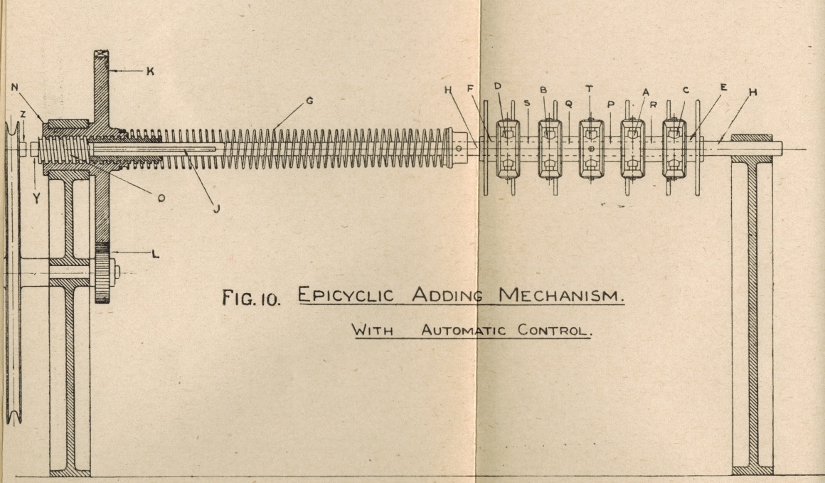
Rotation of the high acceleration adding shafts, which represent bets, is stored and initially read at a slower rate by heavier equipment, which cannot respond as quickly due to inertia, until the inertia is overcome and an angular velocity greater than that of the input adding shafts is achieved. In Figure 10 below, the part to the right of the crease is the adding shaft, with its escapement wheels and epicyclic gears, to the left of the crease is the storage screw and the driving pulley connected to the inertia limited acceleration equipment. The right hand section of this image is shown in greater detail in the following image in the Photo Gallery accessible by clicking on the image and selecting the image thumbnail that follows the one for this image. This image is here to provide more information on the Storage Screw. Perhaps, this use of the word storage here is the first use of this word to imply some form of memory, which has now become a widespread concept in the computer industry.
More after the Image...
Click on the image to go back to the Photo Gallery
George Julius presented a paper to the Institution of Engineers Australia on Thursday May 13th 1920 describing these systems, when a machine that had been built and tested capable of supporting 1,000 terminals and a sell rate of 250,000 bets per minute was demonstrated. It is interesting to note that George Julius was a founder and president of the Institution of Engineers Australia. This image is extracted from George's paper titled Mechanical Aids To Calculation and following is some of the accompanying text from it:
At this point a number of difficulties arise. Firstly, it would be manifestly impossible to accurately rotate these gears by means of the impulses received from the ticket-selling machines. Not only would the power required be excessive and the mechanism very complicated, but the "backlash" in a train of gears such as that described would give rise to endless inaccuracies. "Power" has therefore to be applied to move the gears, and to be so arranged that the issue of tickets on the various ticket issuers controls the extent of the movement.
The epicyclic gears, however, must obviously respond instantly to the records transmitted through them. Thus, if fifty clerks simultaneously issue tickets on the same horse, the records of those sales must instantly be picked up by the epicyclic gears, and as the large counter wheels cannot instantly respond to this demand some form of "storage" gear has to be introduced between the epicyclic gears and the counters to "store" up the records until the counters can he brought up to the necessary speed to record the sales. But this alone would not be sufficient, because if a form of storage gear was put in to merely allow the counter to get up to speed, then if at one instant tickets were passing at the rate of, say, 2,000 a minute on a horse, and at the next instant the issue of tickets ceased, the counters would work up to their speed of 2,000 a minute, and then required to stop dead when running at top speed. Such an arrangement would be obviously impracticable, and the goal has therefore to be so designed as to allow of, firstly, the instantaneous response of the epicyclic gear to the demands made upon it; secondly, the storage of these impulses during such time as the speed of the counters is being brought up to meet the requirements; and, thirdly, the gradual slowing down of the counter as it overtakes the registration of the stored-up records.
In other words, the mechanism that stores up the records has to control a variable speed gear, which will as required gradually speed up or gradually retard the counters, and so avoid all shock to the mechanism.
In the original designs the issue of all tickets of every denomination whether 10s., 1 pound, 5 pounds, or ten pounds, were transmitted to the unit wheel of the counters or numerators. This, however necessitated a very high speed of operation for the unit wheel, because although each unit bet only required one-tenth of a revolution of this wheel, each ten pound ticket required two complete revolutions and in a machine of this type and of relatively small capacity, the speed of the unit wheel frequently reached speeds as high as 200 revolutions a minute. As it was obvious also that tickets of a denomination higher than ten pounds would be required, and even possibly as high as 1000 pounds it was apparent that the practice of passing all registrations through the unit wheel would have to be abandoned.
In the latest type, therefore, only the 10s. and one pound registrations pass through the unit wheel. The 5 pound and 10 pound registrations are passed direct to the 10's wheels, the 50 pound and 100 pound direct to the 100's wheel, and so on. This, again, required some special design, because the 10's wheel had to record not only the 10's carried forward from the additions of records from the 10s. and 1 pound issuers, but also had to register the direct issue of 5 pound and 10 pound tickets, and similarly for the 100's wheel.
It will also be remembered that in describing mechanical systems of numeration, it was pointed out that the only satisfactory form of counter was one in which the various wheels moved instantaneously to the required position. Thus the 10's wheel would be required to move one division at the instant that the, unit wheel moved from 9 to 0. With counter wheels of 18 inches or 2 feet diameter, and with a unit wheel revolving at a high speed, it is impossible to make the units wheel pick up and move the 10's wheel forward at the right instant without excessive shock, and in all these large high-speed counters, therefore, the 10's wheel has to be operated by, "relay " controlled by the movement of the unit wheel, but so designed that the 10's wheel and the wheels of higher denomination move forward without shock. The foregoing conditions have been met, in the following way :-
The epicyclic gears are made as light as possible, and are urged forward by "coil springs" and not by "weights." This ensured the instantaneous response of the epicyclic gears to the demands of the ticket-sellers. The movement of these gears so obtained is transferred to a "storage" screw which serves two functions, firstly, that when the machine is at rest it locks the driving gear which operates the counter wheels, and, secondly that when issues are to be recorded, it stores-up the records until they are registered by the counters. Immediately the tickets are issued the epicyclic gears instantly operate, being driven by the coil spring, and in so doing they turn the screw which then unlocks the driving gear for the counter, and the counter begins to operate. In so operating, this driving gear also moves a nut, which, acting on the storage screw, tends to bring it back to its normal position of rest, and thus again lock the counter driving mechanism. Thus the epicyclic gears in picking up impulses received from the ticket-sellers move the screw backwards, and the, driving gear of the counter is always trying to overtake this movement and thus return the screw to its normal position.
The movement of this screw is so arranged that it also controls a variable speed friction gear through which the counters are driven. During any period of acceleration in the issue of tickets, the screw is withdrawn in the nut faster than the counter operates, and this through the friction gear speeds up the counter, and the nut, in an endeavour to overtake the movement of the screw, and a condition of balance is ultimately established. If the issue of tickets is retarded or ceases, the nut immediately gains on the screw and brings it forward, thereby picking up all the stored-up records, and by means of the friction gear gradually slowing down the counter until when all the records are recorded, it quietly comes to rest. The rotation of the nut also is utilised to continually rewind the coil spring which operates the epicyclic gears, and thus ensure a steady driving effort on these gears.
The whole operation is entirely automatic and the speed is adjusted to suit the requirements of the ticket issuing. The arrangement of gears, screw , and nut is shown diagrammatically in Figure No. 10, and in more detail in Figure No. 11.
The Epicyclic Gears George refers to above are labelled A, B, C, D and T in the image above. The component labelled K is what George refers to as the driving gear for the counter and George also informs us that this driving gear also moves a nut. The nut George refers to surrounds the screw labelled O and is the storage screw body itself, which extends to the right hand extremity of the component labelled G. I think this component labelled G is what George refers to as the Coil Spring. I am not sure, however George refers to locking and unlocking the Counter Driving Mechanism and this probably has to do with components Y and Z in the drawing. Again I am unsure however I suspect the item labelled J is probably the driving shaft for the storage screw labelled O, which is driven by the adder, which is represented in this drawing by the epicyclic gears. Items E, F, P, Q, R and S are all different stages of the adding shaft.
The six longest vertical narrow oblong rectangles in the drawing, that are perpendicular to the adding shaft stages, represent the escapement wheels. These escapement wheels have associated escapement mechanisms, which allow the escapement wheels to rotate one tooth at a time as a result of betting activity. The escapement mechanisms are activated by solenoids when they receive pulses from the attached TIMs (Ticket Issuing Machines). A drawing of an escapement wheel, the escapement mechanism and a solenoid is shown in the second image following this one in the Photo Gallery accessible by clicking on the image and selecting the second image thumbnail that follows the one for this image.
It seems to me that the epicyclic gear D sums the angular displacement of the left two escapement wheels and imparts that to shaft S. It does this by adding the angular displacement of shaft F, which is that of the left hand escapement wheel and adds it to its associated escapement wheel which is the second from the left. The central part of the escapement wheels attached to epicyclic gears is hidden by the epicyclic gears. Then epicyclic gear B sums the angular displacement of shaft S with that of its own associated escapement wheel, the third from the left, and imparts the summed angular displacement to Shaft Q. Similarly, epicyclic gear C sums the angular displacement of the right two escapement wheels and imparts that to shaft R. Epicyclic gear A sums the angular displacement of shaft R with that of its associated escapement wheel, the third from the right, and imparts the summed angular displacement to Shaft P. Finally, epicyclic gear T sums the angular displacement of both shafts Q and P and then imparts that total angular displacement to shaft H. The circle on the intersection of the centre lines of epicyclic gear T and of Shaft H, indicates the connection of gear T with shaft H, that none of the other epicyclic gears have.
The energy to rotate the escapement wheels is taken from the coil spring G. The H shaft is the output shaft of the adder section and this totalled angular displacement representing bet transactions is imparted to the storage screw, which winds the screw labelled O into the body of the storage screw or what George calls the nut, by an amount representing the number of transactions to be recorded. This movement of the storage screw unlocks the body of the storage screw or nut and allows the body or nut to rotate, driven via gear wheel K. This action initially slows the advance of the storage screw and eventually as inertia of the equipment being driven is overcome, the rotational velocity of the storage screw body or nut will exceed that of the storage screw itself and start to return the screw to its rest position from whence it came. In terms of our computer analogy, buffer memory, we could say that when the storage screw returns to its rest position, the buffer memory has been emptied.
There is another analogy to a piece of equipment that is part of the storage screw. The control of what George terms Variable Speed Gear, involving the sensing of the position of the storage screw O when in the vicinity of its rest position, to alter the angular velocity of the nut through the variable speed gear, as a function of the position of the screw, in the electronics era would be called a closed loop servo system.
The system demonstrated to The Institution of Engineers Australia, the subject of this paper in 1920, is a large scale real time multi user system long before the electronics and computing that made these concepts commonplace.
To have a look at the photograph that triggered this interest in the storage screw, have a look at the first photograph in the Brough Park section of the Photo Gallery titled Brough Park Newcastle Upon Tyne 1936, which can be viewed by clicking on the image above and scrolling up to and selecting the image thumbnail with associated text starting One of the many adders in the central processing system, to be installed at Brough Park.
The part of George's paper that is pertinent to this website is presented in the Mechanical Aids to Calculation Chapter of this website.
Thanks to the Institution of Engineers Australia for allowing reprints of any portion of the Mechanical Aids to Calculation publication.