This technology history page contains a photograph, which is one of several belonging to the photo gallery pages, which are part of several pages relating to the invention of the world's first automatic totalizator in 1913 and Automatic Totalisators Limited, the Australian company founded in 1917 by George Julius, to develop manufacture and export these systems.
George Julius' Paper, Institution of Engineers Australia (IEAust)
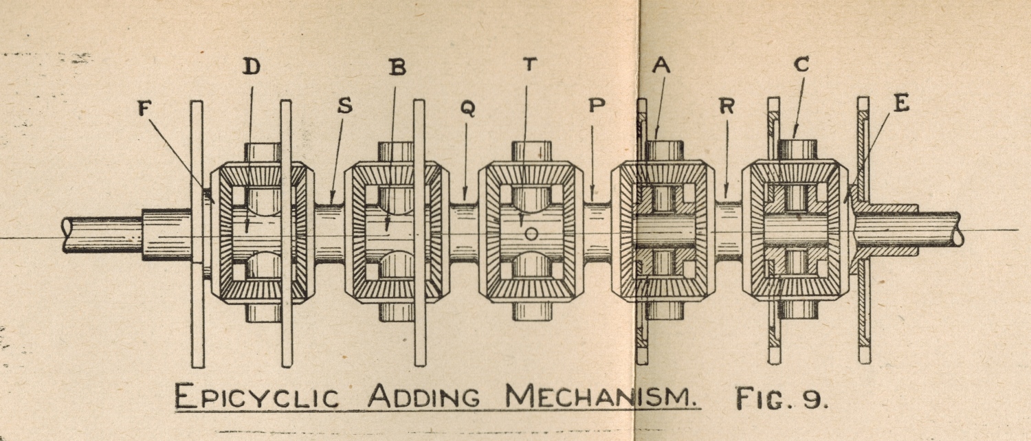
On many of the images displaying adders in this Photo Gallery and other photos throughout this website, the adding shafts and associated components can be seen. These consist of the epicyclic gears, escapement wheels and their associated escapement mechanisms and the solenoids that activate the escapement mechanisms as a result of impulses received from the ticket issuing machines. This image is an engineering drawing of an adding shaft showing the epicyclic gears and escapement wheels. There are varying numbers of escapement wheels and epicyclic gears on a shaft but this is the essence of all of them. The escapement wheels in this drawing are represented by the six longest vertical narrow oblong rectangles, that are perpendicular to the adding shaft stages labelled F S Q P R and E. The epicyclic gears in this drawing are the five groups of four bevel gears, grouped together in such a fashion that in this drawing their perimeter looks like oblong rectangles with chamfered edges and are labelled D B T A and C. More after the image...
Click on the image to go back to the Photo Gallery
George Julius presented a paper to IEAust on Thursday May 13th 1920 describing these systems, when a machine that had been built and tested capable of supporting 1,000 terminals and a sell rate of 250,000 bets per minute was demonstrated. It is interesting to note that George Julius was a founder and president of IEAust. This image is extracted from that paper and following is some of the accompanying text from it:
The paper describes the development of a machine that has been built in Australia capable of meeting such requirements and of recording records received from as many as 1000 independent operators, and at speeds as high as 4000 a second. (Webmasters Notes: What George has described here, is a large scale low response time system.) These machines are capable of both printing and issuing tickets, and at the same time recording the issue of such tickets when issued in great numbers and simultaneously by a number of selling machines.
The machine to be installed therefore, must automatically record from instant to instant the total sales on each horse, and the grand total of all sales, and must display these figures in such a way that they may be easily legible to the public. (What George has mentioned here regarding the instant recording, makes these real time systems.) This last requirement necessitates the use of very large counters or numerators, as the figures require to be legible from a distance of at least 200 feet.
This latter condition necessitates the use of counter wheels of large diameter , even as much as 2 feet, and as the speeds at which they are required to revolve is sometimes great, and the inertia, however lightly they may be constructed, considerable,(sic) they cannot therefore be started or stopped suddenly. Further, also, in such installations it is necessary to locate many of the ticket-selling booths at a considerable distance from the adding machine, which necessitates the use of electric power for the transmission of the records from the selling machines to the recording machine. (What George has mentioned here sounds like a distributed network.)
Here, again, difficulties arise, as the first requirement of a totalisator is absolute accuracy, and the use of electric transmission obviously introduces a possible weakness which has to be guarded against. (Here George introduces a concept that is so important in the digital computer era particularly in real time systems - Reliability) Thus, an electric cable may break, insulation may fail, magnet coils may burn out or short or there may even be a complete interruption in the supply of electric power to the machine. A complete system of safety gear has therefore to be introduced, which will only permit of the issue of a ticket at any booth on any horse if the electric connection between that selling machine and that horse is in order, and electric power available.
This may be more briefly expressed by saying that the whole installation must be so arranged that no ticket can possibly be issued without its issue being correctly recorded and vice versa, that no "record" can be transmitted and recorded without the corresponding issue of a ticket.
One more factor also is of importance. The whole equipment has frequently to be worked at very high pressure during selling operations, and the liability of faulty operation of the ticket-selling machines is thus greatly increased. The design of these equipments has, therefore to be such as to make them as nearly " fool proof " as possible.
The foregoing will have made clear the very peculiar and somewhat exacting conditions that have to be met in order to ensure a successful solution of the problem.
The first and most essential factor is the obtaining of a mechanism which will add the records received from a number of independent operators. (What George has mentioned here regarding the number of independent operators, makes these multi user systems.) This has been done in two ways. The first method, which has met with a certain measure of success in small equipments, depends upon the release of a marble or steel ball whenever a ticket is issued. Further reference to the marble tote has been removed as it is irrelevant. It can be seen in the Mechanical Aids to Calculation chapter of this website. The other system of "collective adding," as it may be called, depends primarily upon the use of a group of super-imposed epicyclic gears. Such a group is shown diagrammatically in Figure 8.
Figure 8 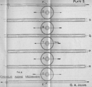
Webmaster's note:
I have included Figure 8 above, as it is an essential part of George's explanation which follows. The six racks George refers to in Figure 8 labelled F S Q P R and E correspond to segments of the adding shaft as labelled in the drawing at the top of this page. The five wheels labelled D B T A C correspond to the epicyclic gears as labelled in the drawing at the top of this page.
Note that the epicyclic gear labelled T in the image at the top of the page, which is the Total gear, is the only one without an associated escapement wheel and drives the output shaft of the adder, which is the innermost horizontal shaft shown at the left hand end of the image at the top of the page. The circle in the middle of the T epicyclic gear represents its connection with the output shaft. The angular displacement of the vertical shaft in epicyclic gear T, represents the sum of the angular displacement of shaft Q ,which is the sum of shafts F and S, with that of shaft P, which is the sum of shafts R and E. It is this vertical shaft of epicyclic gear T, that drives the output shaft of the adder.
In describing this gear, reference will only be made to the process of " addition," but it is obvious that the gear is equally applicable to subtraction. The gear, as shown, is arranged to receive and add records from six operators, and to show the total upon the total wheel marked " T," by rolling this total wheel towards the left, as shown by the arrow. For convenience let it be assumed that a movement of the wheel "T" of 1/4 inch to the left represents the issue of one ticket. The six selling machines are connected to the wheels "A," "B," "C," and "D," and to the racks "E" and "F" respectively. The double racks "P," "Q," "R," and "S " are not connected to selling machines, and are merely portion of the adding mechanism.
Suppose the wheel "A" to be connected to a 10s. issuing machine, and to be so arranged that the issue of each 10s. ticket causes it to roll 1/4 inch to the left, as shown by the arrow. If the operator of the selling machine connected to this wheel "A" then issues a ticket, the wheel will travel 1/4 inch to the left, rolling upon the momentarily fixed rack "R," and thereby moving the rack "P" 1/2 inch to the left. The teeth on the upper face of the rack "P" will then obviously cause the total wheel "T" to roll along the momentarily fixed rack " Q," and thus to travel, as a whole, 1/4 inch to the left. It is seen, therefore, that the movement of the wheel "A" 1/4 inch to the left will of itself cause the total wheel " T" to move 1/4 inch in the same direction.
Similarly, if the wheel "B" moves 1/4 inch to the left it will cause the total wheel " T" to move 1/4 inch in the same direction.
Next take the wheel "C." It is so connected to a selling machine that the issue of a 10s. ticket will cause it to move 1/4 inch to the right, as shown by the arrow. If for the moment none of the other issuers are issuing, this movement of "C" of 1/4 inch to the right travelling along the momentarily fixed rack "E" will cause the rack "R" to move 1/2 inch to the right, and this, by reason of the fact that the axis of the wheel "A" is momentarily fixed, will cause the rack "P" to move 1/2 inch to the left, and thus, as before, move the total wheel " T" 1/4 inch to the left, again recording on "T" the sale of a unit ticket. Obvously the operation of the wheel "D" is the same.
Next consider the rack "E" and assume that it be moved whilst all the other issuers are idle. The rack "E" is caused to move 1/2 inch to the left when the ticket issuer connected to it issues a 10s. ticket. This movement will, through the momentarily fixed wheel "C," move "R," 1/2 inch to the right, which again, through the wheel "A," moves "P" 1/2 inch to the left, and this in turn moves the total wheel "T" 1/4 inch to the left. Similarly for the rack "F."
It is thus seen that unit movement of either of the wheels "A" or "B" to the left, or either the wheels "C" or "D" to the right, will move the total wheel "T" through unit movement to the left. It is also seen that a double unit movement of either of the racks "E" or "F" to the left will move the wheel "T" unit movement to the left.
Now let us suppose that two of these movements occur simultaneously by assuming that the two ticket selling machines attached to the wheels "A" and "C" respectively operate at the same instant. The unit movement of the wheel "C" to the right causes a movement of the rack "R" through twice the distance to the right, and this through the wheel "A," if it were fixed would cause the rack "P" to move twice the unit distance to the left. But at the same instant the centre of the wheel "A" is moved unit distance to the left, and obviously, therefore, the resultant movement of the rack "P" is four times unit movement to the left, and this will move the total wheel "T" through two unit distances to the left, and thus record the sale of two tickets.
A little consideration will show that the whole of the six movements may take place simultaneously, and the gear, therefore, is capable of adding the records simultaneously received from six operators.
In the foregoing description it has been assumed that all these wheels are connected to the 10s. issuing machines, but it is obvious that if, for instance, the wheel "B" were connected to a £1 machine, all that is required is to cause the wheel "B" to move through a "two-unit" distance to the left for every £1 ticket issued. Similarly the same argument would apply to £5 tickets, and tickets of higher value.
It is obvious, however that the gear as shown in diagram No. 8 could not be used, because the racks would have to be of impracticable length, and in practice the racks are replaced by bevel wheels. The various records are then made by the rotation of the wheels A, B, C, D, and hence T about their axes, instead of by the lateral translation of these axes.
This arrangement is shown in Figure 9 (the corresponding parts in the arrangement shown in Figures 7 and 8 being "lettered" the same), and its operation should readily be followed, it being merely necessary to change the motion of translation of the gears shown Figure 8 to one of rotation of the gears shown on Figure 9.
Looking at my comments made regarding some of George's statements above, putting them all together we have a Large Scale, Low Response Time, reliable, Real Time, networked multi user system in 1920, long before the commercial availability of digital computers that made these concepts commonplace! I will also add the observation that at the time I retired in 2012, 92 years later, a transaction rate of 4000 per second, which George Julius mentions in 1920, was considered good performance for digital computer based totalisator systems.
I worked on the development of a PDP11 based totalisator system for Automatic Totalisators Limited, to replace the Julius Totalisators in the Brisbane region. By virtue of the adders in the Julius Totalisators, like the one shown in the drawing above, the Julius Totes that my computer systems were replacing, were capable of something that my new systems were not. Although the new computer systems I introduced into the Brisbane region, were loosely coupled multiprocessors, they were not capable of parallel processing. Each processor sequentially processed every bet, albeit that this happened so quickly that it all looked like it was happening at once. The Julius tote adders could record multiple bets instantaneously as the escapement mechanisms in the adder shown in the drawing above can have any number or all escapements activated at the same instant and the output of the adding shaft will represent all the transactions in the one operation in the same time it took to record one! The engineering staff who worked on the Julius Totes in Brisbane, that I inherited and inducted into the computer era, delighted in reminding me of this fact.
A drawing of an escapement wheel, the escapement mechanism and a solenoid is shown in the image following this one in the Photo Gallery accessible by clicking on the image at the top of the page and selecting the image thumbnail that follows the one for the image at the top of this page.
A drawing of this adding shaft connected to a Storage Screw, which is a mechanical form of memory, is shown in the preceding image in the Photo Gallery, accessible by clicking on the image at the top of the page and scrolling up and selecting the image thumbnail preceding the one for the image at the top of this page.
The part of George's paper that is pertinent to this website is presented in the Mechanical Aids to Calculation Chapter of this website.
Thanks to the Institution of Engineers Australia for allowing reprints of any portion of the Mechanical Aids to Calculation publication.