This history page contains an image which is one of several belonging to the Photo Gallery pages which are part of several pages relating to the invention of the world's first automatic totalizator in 1913 and Automatic Totalisators Limited, the Australian company founded in 1917 to develop, manufacture and export these systems.
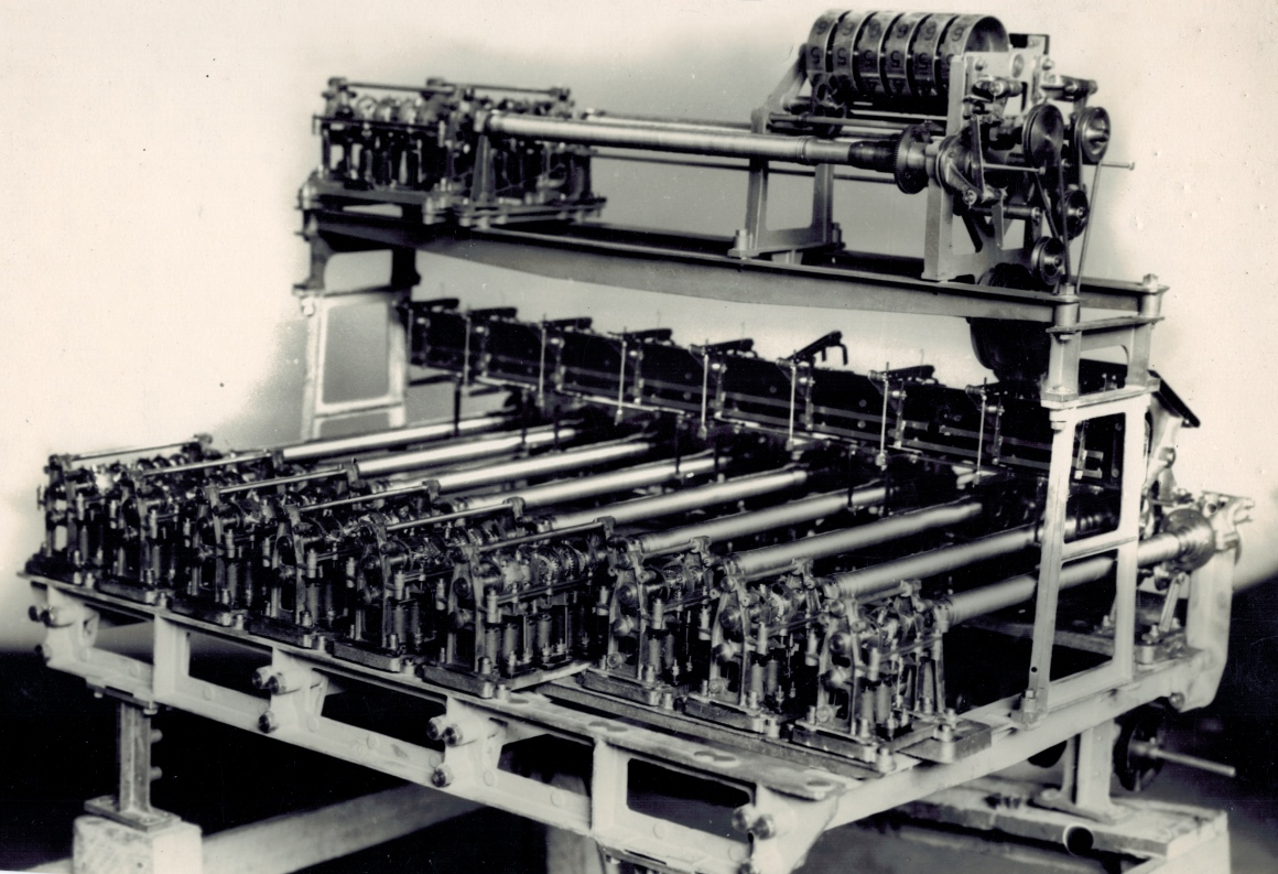
A rear view of a Longchamps Julius Tote adder
This is the rear view of a partially assembled Julius Tote Adder one of many for Longchamps. It is the same type of adder as the one in the third image in the Longchamps Paris 1928 section of the Photo Gallery. This rear view of the adder shows the constituent shaft adder assemblies across the rear of the adder, which forms a triangle with the bottom left corner of the image. There are six long shaft adders and three smaller ones about half as long as the others. Two more shaft adder assemblies are seen on the left hand side of the upper assembly. The adding shafts in the rear shaft adder assemblies connect to the nine large parallel tubular shafts which are Storage Screws that run towards the front of the complete adder. These Storage Screws are a mechanical form of memory. Two more Storage Screws can be seen on the upper level of the complete adder, one partly obscured behind the other, and running across the upper shelf to the right hand side of the upper assembly with all the pulleys. This is mechanical computing on an industrial scale.
More below the image...
Click on the image to go back to the Photo Gallery
The photographers stamp on this photograph reads: HALL & CO. Commercial Photographers 20 Hunter Street Sydney
As the photographer's stamp is Hall & Co in Sydney, I deduce that this photo was taken in the factory in Sydney before the adder was fully assembled and sent to France. This first Automatic Totalisators Limited factory, where these adders were assembled was in Alice Street Newtown. In the shaft adder assemblies at the rear of the adder, the escapement wheels on the adding shafts can be seen. Below these wheels are solenoids that operate the escapement mechanisms that allow graduated rotation of the escapement wheels. The solenoids are activated by impulses from the Ticket Issuing Machines via the Scanners. There is an Engineering Drawing of an escapement wheel, escapement mechanism and solenoid in the Figures from George Julius' paper presented to the Institution of Engineers Australia in 1920 section of the second page of the Photo Gallery. The angular motion of these wheels represents the transaction values. The fewer the teeth on the escapement wheel the greater the movement with one operation and the higher the value. The epicyclic gear arrangement that connects the escapement wheels along the adding shaft cumulatively adds the rotation of the escapement wheels along the shaft such that when it arrives at the storage screw the rotation is the sum of the rotation of each escapement wheel on the adding shaft. There is a drawing of an adding shaft in the second page of the Photo Gallery in the same section as previously mentioned. There are six escapements and solenoids on each of the longer adding shafts and two on each of the shorter shafts next to them and four on each of the two adding shafts on the upper assembly. There are six of, six escapement shafts, two of four escapement shafts and three of, two escapement shafts giving a total of 50 escapements. As the Scanners, multiplexed seven Ticket Issuing Machines (TIMs) onto each escapement solenoid, this adder is capable of supporting 350 TIM terminals. There is an image of two of the Longchamps Scanner Racks in the Lonchamps section of the Photo Gallery. To look at the Scanner Racks click on this image and scroll up and click on the image thumbnail with the associated text starting with Two of the scanner racks.
The Storage Screws operate on a very simple principle that the angular displacement to which a screw is driven into a nut, is equivalent to the angular displacement of the nut required to remove it from the screw, or to return the nut to its starting position if the nut was already mounted on the screw, as is the case for the Storage Screw. Unfortunately, the mechanical implementation of this principle as a memory is not so simple. The purpose of the storage screws is to buffer the rotation of the high acceleration adding shafts from machinery that is slower to respond due to greater inertia. The electronics counterpart to this is a buffer memory. Simplistically, the fast adding shafts screw a grub-screw like screw into the threaded inside of the storage screw shaft called a nut. The lower acceleration equipment at the other end of the shaft attempts to unwind the screw as it accelerates and will eventually return the screw to its starting position, by winding the threaded outer shaft of the storage screw. At some point, the acceleration limited equipment will reach a greater velocity than the adding shafts and start to catch up. There are rods that are visible in the image projecting from this acceleration limited, right hand end of the storage screws on the upper assembly. These rods which I will call Storage Screw Position Sensing Rods are part of a mechanism that detects when the storage screw is returning within the proximity of its resting position causing the start of velocity reduction and finally bringing the storage screw to a gentle stop and locking it, when the screw has returned to its rest position. Conversely, it controls the amount of acceleration during the start of rotation dependent on the rate that the storage screw is advancing. The Storage Screw Position Sensing Rod on the nearest of the two storage screws on the upper assembly, seems to be associated with a vertical lever hinged below the Position Sensing Rod, that can be seen straddling the near end of the storage screw and passing next to the rod to which I presume there is some attachment. This is a part of the adder that has additional equipment yet to be installed, which is a shame as this is a major part of the angular velocity control system which contains what George Julius describes in the extract below as a variable speed friction gear and if it was complete it may have been much more revealing. I have not been able to identify George's variable speed friction gear in this type of adder. I have identified it in another type of adder used in the Western India Turf Club Julius Tote called a Combined Shaft Adder and Indicator Unit. To read this click on the image above, scroll up in the index to the heading Western India Turf Club Bombay 1925 and click on the last image thumbnail in that section with the associated text beginning with the sentence The front view of the unit in the previous image.
As there was more than one method of implementing a Variable Speed Friction Gear in the Julius Tote Adders, I speculate that the Variable Speed Friction Gear in this adder could be implemented by varying the tension of the drive belt with a pulley in the drive train that can alter the tension of the drive belt for each storage screw. George Julius wrote about the Variable Speed Friction Gear in a paper he presented to the Institution of Engineers Australia in 1920. George refers to the counters in the following extract. There are two of these counters on this adder although they, being relatively small drum-wheel counters, are not the most significant acceleration limit. These Adders also drove public display counters with much larger drum-wheels with more inertia and hence greater limit on acceleration. The drum-wheel counter clearly visible in the image above is the highest part of the adder on the right hand side of the upper assembly. The extract from George's paper reads:
The movement of this screw is so arranged that it also controls a variable speed friction gear through which the counters are driven. During any period of acceleration in the issue of tickets, the screw is withdrawn in the nut faster than the counter operates, and this through the friction gear speeds up the counter, and the nut, in an endeavour to overtake the movement of the screw, and a condition of balance is ultimately established. If the issue of tickets is retarded or ceases, the nut immediately gains on the screw and brings it forward, thereby picking up all the stored-up records, and by means of the friction gear gradually slowing down the counter until when all the records are recorded, it quietly comes to rest. The rotation of the nut also is utilised to continually rewind the coil spring which operates the epicyclic gears, and thus ensure a steady driving effort on these gears. There is a drawing of the storage screw in the second page of the Photo Gallery in the same section as previously mentioned.
I have some more speculation about the adder in this image. I previously mentioned that this is the same type of adder as the one in the third image in the Longchamps Paris 1928 section of the Photo Gallery. In that image file I likened the Storage Screws and their control to a much later device from the electronics era called a closed loop servo system. I also speculated there about the possibility that the Mercury Pot Switches in this adder could be used as a variable resistor and not just be used as a switch. I wrote in that file: If they were suitable as a variable resistor, they could be used to vary current in a circuit, as a means of variable control, which is an essential part of a closed loop servo system. This would fit in well with the fact that the immersion of the electrodes in the pots is controlled by the storage screw position sensing mechanism providing the feedback path of the closed loop servo system. If this electrical control could be linked to the screw that tensions the springs that seem to be linked to the tension applied by the tensioner pulleys, then we will have closed the loop of the closed loop servo system, and would have a complete picture of the storage screw's workings in this particular type of Julius Tote adder. These Mercury Pot Switches are not visible in this image however seven of the nine of the Mercury Pot Switch Activating Arms are visible. Sitting across the front part of the adder a wide short board can be seen mounted vertically, spanning the width of the adder and attached to the front side of the vertical, bridge like section support assemblies. This board is located above and crosses the far ends of the nine Storage Screws previously identified and is located below and parallel to the top shelf of the bridge like section with its additional two shaft adders, their respective storage screws and associated equipment on top. Straddling the top of this board seven short Mercury Pot Switch Activating Arms can be seen running parallel to the Storage Screws. All the arms are horizontal except the sixth one from the left hand side which is seen in its raised or off position. The two pronged fork can be seen at the end of this raised Switch Activating Arm and this is the shorting part of the Mercury Switch. When in the lowered position each prong sits in a separate bowl of mercury effectively closing the switch by shorting out the two Mercury Pots which constitute the terminals of the switch. There are another two more Mercury Pot Switch Activating Arms to the right of the seventh visible one identified, part of the eighth one is visible and the ninth completely hidden by the right hand vertical bridge support assembly. There are nine Mercury Pot Switches in this part of this adder one for each of the Storage Screws below. Eight out of the nine vertical rods can be seen, that connect the Mercury Pot Switch Activating Arms near each of the respective arm hinges, to their related Activating Lever Arms below, that jut out from underneath the board being described.
Having introduced the electronic concept of a closed loop servo system being analogous to this electromechanical storage screw control system and George's variable speed friction gear as being an important part of this control system, as well as having described the location and look of this board, my speculation follows. I never worked on the Julius Totalisators however I spent my time with Automatic Totalisators Limited working on the computer based Totalisator Systems in both hardware and software engineering. Although this and similar view images I have of this type of adder do not have sufficient resolution to be sure, there are aspects of this board I find resemble very familiar concepts to me. Two light coloured parallel bars can be seen spanning the width of this board. These look like bus bars to me. Not being clear enough to identify their depth, they could even be printed circuit tracks. As the Longchamps system to which this adder belonged went live in 1928, I think printed circuit boards had not at that time been invented so this is unlikely, leaving the possibility that these are metal conductors attached to the board. If this is an electrical bus bar, as the Julius Totes operated on 120V DC that could be what this bus bar carries. This would not surprise me as I do not think there was anything remotely resembling Workplace Health and Safety in those days, which would require them to be insulated. Below each of the Mercury Pot Switch Activating Arms there seems to be brighter vertical strips between the upper and lower bars mentioned. If the two horizontal parallel bars are bus bars I think it is unlikely that these vertical bars are simply metal bars as these would short out the bus bars. A possibility is that they are resistors. What consolidates this idea to me is that on each of these vertical strips there appears to be a metallic looking object in contact with them. As it seems evident that these objects can move vertically along their respective vertical strips, moved by vertical arms also attached to their respective Mercury Pot Switch Activating Arms, I will call this type of object a wiper. If the wipers do indeed wipe up and down these vertical strips and if the strips are resistors, along with the wiper it reminds me of a variable resistor used as a potentiometer. On one hand, as I am unable to detect any electrical connections to these wipers, it leaves a big question as to whether there is anything electrical about this part of the adder at all. On the other hand however, in the text contained in the page presenting the front view of this adder, I concluded that it seems highly likely that most if not all of the electrical wiring of these adders was performed on site. Not only has this electrical wiring not been completed or even started in this view of the adder, the adder is only partially assembled so there is additional mechanical work yet to be completed. Failing to find any mechanical purpose for these vertically moving wipers from photographs, I am left with the impression that the electrical view of this board is far more likely. This being the case it supports my quote in the previous paragraph particularly the extract If they were suitable as a variable resistor, they could be used to vary current in a circuit, as a means of variable control. Due to the inability to identify the electrical wiring for these wipers and what part of the machinery they might control, I cannot deduce anything further from these observations except to reiterate that there is one of these for every one of the nine Storage Screws in this part of the adder.
Having left the above observations dangling, there are no shortage of mysterious aspects to these tantalising photographs. If you look at the far ends of the Mercury Pot Switch Activating Arms that are laying flat, you can see very faint traces of what appears to be very light wire rising perpendicularly above the Activating Arms. They seem to have a small loop at the top of them. These seem to be such light wire that it seems at odds with the solid structure of the rest of the adder. What their function is I have no idea, probably not electrical as they do not appear to go anywhere and they do not seem robust enough to perform any mechanical function, possibly an end stop for the raising of the Activating Arms of some sort or a drive disconnect wire to be pulled by service staff to allow the Activating Arms to be manually moved to perform some service function. All this know-how has long been lost and in the case of this adder in particular, it is not possible to determine much of the functional details from the remaining photographs that exist.
I was concerned that I may have gone overboard with the amount of speculation in this page, bordering on being fanciful. For this reason I sent a link to this page, to a group of people remaining, who had worked on the latter-day Julius Totalisators before they were completely replaced by digital computers, or had a big interest in them to get their opinion. The most pertinent reply was from Bob Moran. Bob is a mechanical engineer who has done much restoration work on Julius Totes for exhibition purposes, long after they ceased operation. Bob has also created what he calls the Discovery Shed to inspire young minds and generate interest in Science Mathematics and Engineering. The pertinent comment reads: Whether you are right or wrong is not the issue, at least you have expressed an opinion, now it is up to others to postulate. Neville Mitchell, a long serving Automatic Totalisators Limited Engineer and Manager and the best company historian I know, also made an interesting comment in an email sent on 10 December 2020. The pertinent comments read: Reading through your description of the Longchamps adder and scanners I think you did a magnificent very informative work of a now long time ago Tote Machine. Strangely Longchamps was not a common topic of conversation during my 32 years at ATL, Only thing I recall was that John Pickering was posted to London and I suppose he would have visited Paris? Will ask him next week. Neville's comments are additionally pertinent as he actually worked on the engineering side of the latter-day Julius Totalisators. These latter-day Julius Totalisators were designed well after this Longchamps system however much of the design persisted throughout the Julius Tote permutations. The main difference in this case is that the Storage Screws were no longer necessary after George Julius invented the first odds calculator so Neville will not have seen a Storage Screw either.
As previously mentioned, George Julius presented a paper to the Institution of Engineers Australia on Thursday May 13th 1920 describing these systems, when a machine that had been built and tested capable of supporting 1,000 terminals and a sell rate of 250,000 bets per minute was demonstrated.The part of George's paper that is pertinent to this website is presented in the Mechanical Aids to Calculation chapter of this website.